Quantcast
Channel: Electro help
Viewing all 2033 articles
Browse latest View live

SONY HCDRG575 _ COMPACT DISC DECK RECEIVER - POWER AMPLIFIER - SUB-WOOFER - SCHEMATIC DIAGRAM

$
0
0
SONY HCDGX355 – HCDGX555 - HCDRG270 - HCDRG475 - HCDRG575 _ COMPACT DISC DECK RECEIVER
Power Amplifier [STK-403] _ Sub Woofer [STK-404] _ Circuit Diagram
HCD-GX355 MHC-GX355 >> HCD-GX555 MHC-GX555 >> HCD-RG270 >> MHC-RG270

HCD-RG475 >> MHC-RG475

HCD-RG575 >> MHC-RG575
US Model/Canadian Model - HCD-GX355/GX555
AEP Model/ UK Model / Australian Model - HCD-RG270/RG475
E Model - HCD-RG270/RG475/RG575

HCD-GX355 is the amplifier, CD player, tape deck and tuner section in MHC-GX355.
HCD-GX555 is the amplifier, CD player, tape deck and tuner section in MHC-GX555.
HCD-RG270 is the amplifier, CD player, tape deck and tuner section in MHC-RG270.
HCD-RG475 is the amplifier, CD player, tape deck and tuner section in MHC-RG475S.
HCD-RG575 is the amplifier, CD player, tape deck and tuner section in MHC-RG575S

Specifications
North American model: HCD-GX555
Front speaker
Continuous RMS power output (reference):
145 + 145 watts (6 ohms at 1 kHz, 10% THD).  Total harmonic distortion less than 0.07% (6 ohms at 1 kHz, 80 W)
Sub woofer
Continuous RMS power output (reference):
170 watts (6 ohms at 80 Hz, 10% THD) Total harmonic distortion less than 0.07% (6 ohms at 80 Hz, 90 W)

European and Russian models: HCD-RG475
Front speaker
DIN power output (rated): 110 + 110 watts (6 ohms at 1 kHz, DIN)  Continuous RMS power output (reference):
140 + 140 watts (6 ohms at 1 kHz, 10% THD)
Music power output (reference):
280 + 280 watts (6 ohms at 1 kHz, 10% THD)
Sub woofer
DIN power output (rated): 130 watts (6 ohms at 80 Hz, DIN)
Continuous RMS power output (reference):
160 watts (6 ohms at 80 Hz, 10% THD)
Music power output (reference):
320 watts (6 ohms at 80 Hz, 10% THD)

HCD-GX355
Continuous RMS power output (reference):
150 + 150 watts (6 ohms at 1 kHz, 10% THD)
Total harmonic distortion less than 0.07% (6 ohms at 1 kHz, 80 W)

HCD-RG270
DIN power output (rated): 80 + 80 watts (6 ohms at 1 kHz, DIN)
Continuous RMS power output (reference):
100 + 100 watts (6 ohms at 1 kHz, 10% THD)
Music power output (reference):
200 + 200 watts (6 ohms at 1 kHz, 10% THD)

POWER AMPLIFIER SCHEMATIC
SUB-WOOFER SCHEMATIC


HOW TO DISASSEMBLE SONY HCD-GX555 CD MECHANISM DECK _ OPTICAL PICK-UP (KSM-215DCP)

$
0
0
DISASSEMBLE PROCEDURE _ SONY HCD-GX355 _  HCD-GX555_HCD-RG270_HCD-RG475_HCD-RG575 CD MECHANISM DECK _ OPTICAL PICK-UP (KSM-215DCP)
CD MECHANISM DECK


OPTICAL PICK-UP (KSM-215DCP)
SENSOR BOARD
MOTOR (TB) BOARD
MOTOR (LD) BOARD
Click on the pictures to Zoom In

YAMAHA YST-SW315 - Sub-Woofer - SCHEMATIC DIAGRAM - ADJUSTMENTS

$
0
0
Yamaha YST-SW315 _ Sub-Woofer _ Circuit Diagram & Adjustments [A1145_C2705]
ADJUSTMENTS
Idling Adjustment
* To stabilize operation of the amplifier, turn ON the power with no input signal and wait for 2 to 3 minutes in non loaded condition before the adjustment.
* Confirm that the voltage across the terminals TP11 and TP12 is 10 mV to 200 mV.  If it exceeds 200 mV, open (cut off) R172.
Confirmation of AUTO STANDBY operation.
Setting
# Turn off the power switch located on the rear panel.
# In order to shorten the time required for operation check; connect a 10kΩresistor at both ends of R252 on the MAIN  P.C.B.
# Connect the output signal from the signal generator to the INPUT 2 / L/MONO terminal of the unit.
# Set the signal generator for the sine wave of 100Hz, 8mV.
# Turn on the power switch located on the rear panel.
Confirmation
* Set the AUTO STANDBY switch to the LOW position.
* Turn on the STANDBY/ON switch.
* The display LED lights up (green) and its colour changes
* To red after 5 to 10 seconds.
* Turn off the STANDBY/ON switch.
* The display LED goes off.
* Set the AUTO STANDBY switch to the HIGH position.
* Turn on the STANDBY/ON switch.
* The display LED lights up (green) and its colour remains Unchanged even after time has elapsed.
* Turn off the STANDBY/ON switch.
* The display LED goes off.
After confirmation
* Turn off the power switch.
**  Disconnect the 10k Ωresistor connected to both ends of R252.
SCHEMATIC [Circuit Diagram] & PWB
Click on the pictures to Magnify

YAMAHA - YST SW030Y - YST SW101SS - SUB-WOOFER - DISASSEMBLY PROCEDURES _ Printed circuit boards _ Circuit diagram

$
0
0
YAMAHA YST- SW030Y _ YST SW101SS – Sub-Woofer_DISASSEMBLY PROCEDURES _ Printed circuit boards _ Circuit diagram  {STK404-120Y}
DISASSEMBLE PROCEDURE
Removal of Driver
* Remove 4 screws (1) and then remove the Base.
* Remove 4 screws (2) and then remove the Driver.
* Disconnect the connector connected to the terminal of the Driver.
Removal of Rear Panel Ass'y
* Remove 8 screws. * Screws (3) are identified with arrow marks (ß ).
* Pull out the rear panel ass'y.
When Checking the P.C.B
# Connect all the connectors removed during disassembly back to the original positions.
# Spread the Rubber sheet and cloth for insulation purpose and place the rear panel ass'y on it.
PCBs
SCHEMATIC (Circuit Diagram)
Click on the pictures to Magnify

ELSYS - SET-TOP BOX - SCHEMATIC (Circuit Diagram)

$
0
0
Elsys - Set-top box - circuit diagram [Click on the schematics to Zoom In]
DISPLAY
MODULATOR
TUNER-VIDEO
AUDIO
POWER [SMPS]

SONY KDL-32EX725 - KDL-40EX725 - KDL-55EX725 – LED BLINKING (Error) CODES and FAULT DETAILS

$
0
0
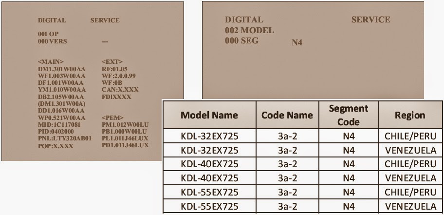
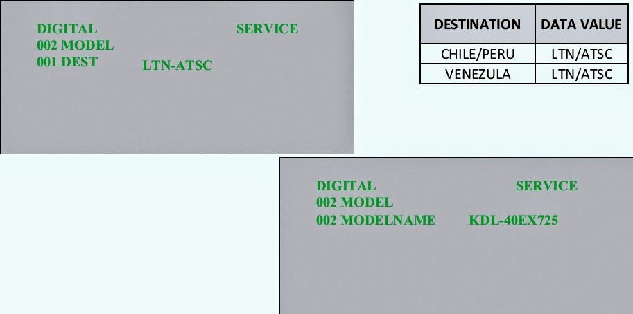
KDL-32EX725 RM-YD062  CHILE/PERU | KDL-32EX725 RM-YD062  VENEZUELA
KDL-40EX725 RM-YD062  CHILE/PERU | KDL-40EX725 RM-YD062  VENEZUELA
KDL-55EX725 RM-YD062  CHILE/PERU | KDL-55EX725 RM-YD062  VENEZUELA
LED Blinking Codes [Error Codes] & Self Check Function
  If an error occurs, the standby LED will automatically begin to flash. The number of times the LED flashes translates to a probable source of the problem.
  If there is more than one error, the standby LED will identify the first of the problem areas. If the Self check screen displays a “0”, no error has occurred.
2X Blink - Main Power Error:  A 2X protection mode blink pattern can be activated due one of the following defects.
* Loss of REG12V (LVP)*
* Loss of -125V (Single Line)
* Excessive -125V Level (OVP)*
* Loss of Power-ON Signal
* Excessive PFC Voltage (OVP)
* Excessive PFC Temperature (OTP)
# Low Voltage Protection (LVP)
# Over Voltage Protection (OVP)
  A loss or excessive condition of the REG12VDC secondary voltage from the main power supply IC6351 will cause a 2X blink pattern on the standby LED. The 12Vdc can be checked at CN6704/pin 16.  If the measurement is 0V or rises above 12Vdc (approaches 15V) before the TV shuts down the Power Supply Board is defective. If approximately 12Vdc is present and remains below 12Vdc before shutdown then further troubleshooting is necessary to determine the defective component.    After confirming proper REG12V levels, check the Negative LED Backlight supply levels. A loss or excessive condition of the negative supply will cause a 2X blink failure. The voltage level can be checked at CN6701/pins 1 & 3 before the TV shuts off. There will be 2 to 4 wires (Red & Blue) depending on the panel size. All individual wires   should be checked for proper voltage level. In normal operation the voltage level will initially rise to approximately -175V and then should
Regulate down to between 89V and 125V depending on the Back light adjustment in the User Menu.     If one of the negative supplies is 0V or rises above -175V before shut-off then the Power Supply Board is defective, replace it to fix the problem.  A defective X-Reality processor on the Main Board or Switch circuit on the Power Supply Board will cause a loss of the Power-ON signal (2X). To determine which component is defective check the Power-ON voltage level at CN6704/pin 1. In normal operation 3V should be measured. If the 3V is present before shut-off then the Power Supply Board is defective. If 0V is measured before shut-off then the Main Board is defective.  Finally, there are PFC protection circuits on the Power Supply Board that when activated will cause a 2X blink protection mode. The PFC circuit is monitored for both over-voltage and over-temperature.          Therefore, if all the previously discussed circuits checkout okay, there could still be a problem on the Power Supply Board in the PFC circuit causing the 2X blink. Replacing the Power Supply Board will fix the TV.
3X Blink- DC Regulator/Audio Error:  The Audio error can occur due on of the following error conditions.
Defective DC Regulator on Main Board
Shorted or Damaged Speaker Connections
Defective Audio Amplifier (Main Board)
Loss of AU12V (Open F4200 on Main Board)
Loss of AU12V (Open Fuse on Power Supply Board)
The first thing to check when a 3X blink protection mode occurs is the physical condition of the speakers and speaker connections. The speakers should measure 8 ohms. Shorted speakers or connections can cause a 3X blink protection mode.  If the speakers and connections check okay, then the defective component is on the Main Board. An open F4200, defective DC Regulator, or defective Audio amplifier will cause a 3X blink protection mode. In any of these cases, replace the Main Board to fix this condition.  A defect on the Power Supply Board can cause a 3X blink protection mode and shut-off.  Check the AU12V level at CN6704/pin 14. If 0V is measure before 4X Blink – Balancer Error.
  The 4X error code is only used on models incorporating local dimming LED back-lighting. If a failure occurs on the LD board the TV will shut down and display this diagnostic code. Models using conventional non-local dimming LED back-lighting do not utilize this error code.re shut-off the Power Supply Board is defective.
5X Blink - T-CON Error
  The 5X blink protection mode indicates a communications error between the T-CON Board and the X-Reality microprocessor on the Main Board. If the T-CON is available for replacement, replace the T-CON. If the T-CON is not available, the LCD panel must be replaced since the T-CON circuit is part of the LCD panel assembly. In rare cases a loose or defective LVDS cable could also be the cause.
6X Blink Back-light System Failure
NOTE: All models will make two attempts to power up before a 6X is activated. The SONY logo (Back-light) may or may not display on the screen. However, the splash tones will be heard two times. After the second attempt the TV will turn off and the standby LED will blink a 6X protection mode. (Note: The splash tone may not be heard if it is turned off or the volume is set to minimum.)  If a 6X blink pattern is activated then a defect has occurred in one of the following areas.
* Defective Panel LED(s)
* Defective Power Supply
  When troubleshooting a 6X back-light system failure it is key to notice if the back-lights illuminate before the TV shuts off. The following list shows the possible back-light status and blink pattern and the possible failed components.
1. Momentary Back-light and 6XDefective LED(s) (LCD Panel Assy.)
2. No Backlight and 6X: Replace Power Supply
  In most cases, if the Sony logo (Back-light) momentarily illuminates and the TV shuts off and a 6X is activated than one or more of the back-light LEDs are defective. The LCD Panel assembly panel must be replaced for a defective LED. However, before replacing the LCD panel assembly checks for a complete loss of the Negative Back-light (-89V to -125V) power supply. The -89V to -125V power supply can be checked at CN6702/pins 1 & 3.
  If there is no back-light before the TV shuts off and activates a 6X, than check the “Back-light ON” signals from the TV microprocessor and the Positive (+145V) Back-light power supply from the Power Supply Board. The BL-ON signal can be checked at CN6704/pin 5 and the +145V at CN6701/pins 1 & 3.  If the “Back-light-ON” signal is okay and the Positive Power supply is missing then the Power Supply Board is defective. However, if the Back-light-ON is missing then the X-Reality Microprocessor is defective and the Main Board must be replaced to repair the problem.
7X Blink - Temperature Failure
  These models do not display a temperature warning OSD dialogue box before shutting off and going into a 7X standby LED blink pattern. The main objective when a 7X blink pattern occurs is to determine which of the following possible defects is causing the excessive temperature condition indication.
Excessive Ambient Room Temperature
Dust or Debris Blocking the TV Ventilation Apertures
Defective Temperature Sensor or X-Reality Microprocessor (Main Board) The first step is to notice how long it takes the TV to shut off and trigger a 7X blink protection mode.  If the TV has an actual excessive temperature condition it will take a considerable period of time to shut off and indicate a 7X blink protection mode. This is because it will take time for the TV components to heat up and for the temperature sensor to detect the excessive temperature and shut the TV off.
If the TV takes a considerable period of time to shut-off check the following items:
* The TV should not be located too close to any heating devices.
* The TV should have at least 4 inches of clearance around the sides & rear, and 11 inches of clearance over the top to ensure adequate ventilation.
* Check that all vented areas on the TV are clear of all dust and debris.
* If the TV shuts off immediately after Power-ON then one of the following components has failed (Not an Actual Excessive Temperature Condition).
# X-Reality Microprocessor (Main Board)
# Temperature Sensor (Main Board)
In either case the Main Board must be replaced to fix the problem.
  The Diagnostic Table provides an overview of the number of times the standby LED blinks and the possible location.
VIEWING THE SELF CHECK DIAGNOSTIC HISTORY
  It is possible to bring up past occurrences of a failure for confirmation on the Self Check diagnostic history screen. This feature is useful for failures which are intermittent or when the customer is not sure what is causing the television to shut down.
* TV must be in standby mode. (Power off).
* Press the following buttons on the Remote Commander within a second of each other:
DISPLAY > CHANNEL-5 > VOLUME-[--] > POWER
* NOTE: This differs from accessing Service Adjustments Mode (Volume +)
CLEARING THE SELF CHECK DIAGNOSTIC LIST
  Since the diagnostic results displayed on the screen are not automatically cleared, always check the self-diagnostic screen after you have completed the repairs to be sure you have cleared the result display to “0”. 
To clear the Error history and Error count press { 8 > 0 }.
RESETTING THE LCD PANEL OPERATING HOURS
  The 3 sets of numbers displayed on the lower left corner of the screen indicates the total accumulated operating hours of the television and the operating hours of the LCD panel. Total operating hours is on the left, boot count in the centre and panel hours in the right group (The centre numbers are not used.)
To clear the LCD Panel operating hours of the LCD Panel after replacing the panel, press {7 > 0}
EXITING THE SELF CHECK DIAGNOSTIC SCREEN
  To exit the Self Diagnostic screen, turn off the power to the TV by pressing the POWER button on the remote or the POWER button on the TV.
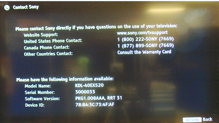
SELF CHECK SCREEN DISPLAY
CLICK ON THE PICTURES TO MAGNIFY

KDL-32EX725_KDL-40EX725_KDL-55EX725 SONY LCD Digital Color TV_SOFTWARE UPDATE AND OTHER DETAILS

$
0
0
SONY KDL-32EX725_KDL-40EX725_KDL-55EX725LCD Digital Color TV_SOFTWARE UPDATE AND OTHER DETAILS   {AZ2-F Chassis Segment: 3a-2}
  The televisions of today have advanced to the point where they are not simply a television anymore. They are evolving into devices that are designed to integrate with numerous other devices found in the home. Some examples are: Portable audio and video devices, still cameras, home computer networks and accessing the internet to name a few.  Communications with these varying devices requires that the television be compatible with varying communications protocols.  Although standards are detailed for each of these protocols, the real world dictates that occasional errors may occur that could prevent devices from operating or communicating properly.  Keeping the software in the television up-to-date is a procedure that is normally handled by the owner of the television. Most customers who own computers and other digital devices are familiar with and are accustomed to updating the software in their products. If a customer contacts the Sony Customer Support Centre and it is deemed to be correctable with a software update, the issue is handled at the customer level.
SOFTWARE UPDATES FOR SERVICE PERSONAL
The models in this manual utilize a “generic” type Main Board. In the past, many different Main Boards needed to be stocked due to differences in software requirements. The software loaded on the board was specific to the model and its features along with the type of LCD panel installed during production. Replacement Main Boards are now stocked with basic software. Once the replacement board is installed in the unit, the most current software needs to be installed using a USB thumb drive containing the necessary software downloaded.  This new method of supplying Main Boards significantly reduces the complexity of replacing LCD panels and Main Boards. Information about the LCD panel is stored on the T-CON circuits. This information is automatically loaded onto the Main Board when the TV is powered up. With the correct software version the Main Board and/or the T-CON or LCD panel can be replaced more efficiently. In addition to software installation, service adjustment information may need to be modified or verified to complete the service of the TV. 
SOFTWARE UPDATE RESPONSIBILITY
  Software updates are designed to be performed by the customer.   Warranty repairs in which the issue can be resolved by a software update are not reimbursable. Most issues involving software updates are handled by the customer service center and should not be directed to an authorized service center. It is the responsibility of the servicer to prevent service calls for issues that involve software updates. Exceptions to this are certain cases whereby the customer is unable or unwilling to perform the task. In this situation, the service will be notified and receive the proper authorization for reimbursement.
CONTACT THE AUTHORIZED SERVICE CENTRE FOR SONY TO GET MORE DETAILS ABOUT THE SOFTWARE UPDATE AND TO GET THE LATEST SOFTWARE.  It is advised to allow them to do this work, as it is a skilled one.

CHECKING THE SOFTWARE VERSION
  The easiest way to check the version of software that is currently on the TV is to access the Contact Sony screen by using the customer menu.
EXAMPLES OF SOFTWARE CORRECTABLE SYMPTOMS
Most symptoms that are correctable by software updates involve communications issues with other devices or minor glitches in the operation of a specific function. Below is a list of some of the symptoms that may be corrected with a software update:
*  Fluctuations in picture brightness
*  Intermittent picture freezing or noise
*  Problems with certain inputs (especially HDMI)
*  Intermittent or distorted audio
*  Erratic remote control operation
*  Unit turns on and off by itself
*  Loss of color
*  Internet connectivity
*  certain features not working correctly (photo or video file viewing)
TO ENTER SERVICE MODE
TV must be in standby mode. (Power off).
Access Service Mode by pressing the following buttons on the Remote Commander within a second of each other.
DISPLAY > CHANNEL-5 > VOLUME {+} > POWER
The DIGITAL Service Menu displays.
NOTE:There are 3 Service Menus for this model,
DIGITAL, CHASSIS, and VPC
> If the DIGITAL Service Menu is not displayed, press JUMP or OPTIONS on the Remote Commander.
 VIEWING OR CHANGING SERVICE DATA
Within each Service Menu are Categories and data information.
Use the buttons on the Remote Commander to review or change the service data.
>> To change the Category, press 2to move to the Next Category or press  5to go back to the Previous Category. {Note:Pressing 2 or 5 only changes the Categories within the Service Menu displayed.}
>> To change the adjustment item, press 1 to move to the Next Item or  4 to go back to the Previous Item.
>> To change the Data Value, press 3 to increase the Data Value or 6 to decrease the Data Value.
>> Press MUTING then press  0to WRITE (Save) the changes.
>> To exit service mode, press HOME or turn the TV power off.
VERIFYING SERVICE ADJUSTMENTS
The following procedures should be performed after updating the software to ensure that the service adjustment data is accurate.
* Verify the Segment Code
* Verify the Destination
* Verify the Model Name
VERIFYING THE SEGMENT CODE
After updating the software, go into Service Mode to verify the Segment Code data value is set.
CAUTION: Selecting the incorrect destination may require replacing the Main Board.
* TV must be in standby mode. (Power off).
* Access Service Mode by pressing the following buttons on the Remote Commander within a second of each  other:
DISPLAY à CHANNEL-5 à VOLUME + à POWER
Press 2 to move to the 002 MODEL category.
Using the table, press 3 to increase the data value or 6 to decrease the data value, to select the correct segment code data value.
VERIFYING THE DESTINATION & THE MODEL NAME
The correct model may need to be selected after updating the software.
Press 1 to move to the 001 DEST item.  Using the table, press 3 to increase the data value or 6 to decrease the data value, to select the correct destination of the TV.
The correct model may need to be selected after updating the software.
Press 1 to move to the 002 MODEL item.
If the correct model does not display, press 3 until the model displayed matches the model of the TV.
Press MUTING then press 0 to WRITE (Save) the changes.
To exit service mode, press HOME or turn the TV power off.
RESETTING THE TV TO FACTORY CONDITION
Use the following instructions to restore the User Adjustments and Channel Memory settings to the preset factory conditions.
> While holding down the on the Remote Commander, press the POWER button on the TV Switch Unit of the set.
> The set restarts and displays the Initial Setup screen. This may take several minutes.
RESETTING THE TV TO FACTORY CONDITION USING SERVICE MODE
> TV must be in standby Mode. (POWER off).
> Press the following buttons on the Remote Commander within a second of each other:
DISPLAY >  Channel 5 > Volume +>   POWER.
> If necessary, press JUMP or OPTIONS to go to DIGITAL mode.
> Press 8.  “SERVICE” changes to green RST.
> Press MUTING.  RST executes the command and displays EXE.
> Press 0.  EXE-RST displays green, then red indicating the TV is writing the data.  When the process is complete the green SERVICE text displays and the LED display.
> Cycle AC Power (Unplug and Plug AC Cord from the AC Outlet).   The set restarts and displays the Initial Set-up screen. This may take several minutes.

LCD DIGITAL LCD TV - SONY KDL-32EX725_40EX725_55EX725 - Circuit Boards layout and Functions

$
0
0
Sony KDL-32EX725_40EX725_55EX725– LCD DIGITAL TV _ Boards layout to different models to this LCD TV & the function details
Universal Remote Control Set-up Code list [With different brand remote controls to Sony TVs]
SPECS: General
Television system:
Analog: NTSC 3.58/ PAL-M / PAL-N
Digital: SBTVD
Channel coverage:
VHF: 2-13, UHF: 14-69
CATV (Analog): 1-135
COMPONENT IN
YPBPR(Component Video)
Signal format: 480i, 480p, 576i, 576p,720p, 1080i, 1080p
AUDIO
HDMI IN 1/2/3/4
HDMI: Video: 480i, 480p, 576i, 576p, 720p, 720/24p/30p, 1080i, 1080p, 1080/24p/30p
HDMI: Audio: Two channel linear PCM 32, 44.1 and 48 kHz, 16, 20 and 24 bits, Dolby Digital
Analog audio input (minijack) (HDMI IN 4 only)
ARC (Audio Return Channel) (HDMI IN 1 only)
Speaker output: 10 W + 10 W
CIRCUIT BOARDS' LAYOUT AND FUNCTIONS DETAILS
  The primary circuits contained in the AZ2-F chassis for the consists of a Main Board (designated as the BATV board), Power Supply Board (designated as the G10A Board for the 32” models, G4B Board for the 40” models, and G6A Board and G8A Board for the 55” models), the Motion Sensor (HMS3 Board), the IR Board (HLR2 Board), the Switch Unit, and the LCD Panel assembly.
MAIN BOARD
  Common to all models the Main Board, designated as the BATV Board, contains the TV control, video, and audio processing circuitry.  All these functions are accomplished using the X-Reality Processor.
TUNER
  The tuner is a combination ATSC/NTSC unit. It can receive traditional analog NTSC signals via cable or terrestrial along with ATSC digital signals via terrestrial (8VSB) or cable (64 or 256 QAM)
AUDIO AMPLIFIER
  The audio amplifier (IC4601) amplifies the digital audio output of the X-Reality processor and sends it to the speakers.
TEMPERATURE SENSOR
  The temperature sensor detects over-temperature conditions on the Main Board, LCD Panel, or ambient room temperature and sends the shut-down signal to the processor.
X-REALITY PROCESSOR
  IC9000 performs the majority of the necessary audio and video processing on the main board.  TV Microprocessor: The CPU internal to the X-Reality processor controls all aspects of the television functions. Input from the user along with monitoring of critical circuits is also performed by this CPU.  Digital Audio and Video Decoder: The MPEG2 and Digital Dolby audio streams are received from the tuner for decompression. All video sources which are not native 1920 X 1080p 60HZ are scaled to this resolution. Digital audio content is output to the class D amplifier for processing and amplification.
HDMI Input and Switching: The customer can select the HDMI1, HDMI2, HDMI3, HDMI4 input.    Each HDMI input contains a common EDI NVM (not shown) to provide display information data to any device connected via the HDMI inputs.  LVDS Transmitter:Integrated into IC9000 is a Low Voltage Differential Signalling (LVDS) transmitter. This circuit converts the 8-bit parallel RGB video information into a set of high speed serial  lines for noise-free transmission to the T-CON circuits located internally to the LCD panel.  Scan Converter: Signal processing circuit that performs resolution conversion (aspect ratio) and interlaced to Progressive scan (IP) conversion.
POWER SUPPLY
  There are different Power Supply Boards used in the models in this manual. The type of board depends on the size of LCD panel. They are:
G10A-Board (32”)
G4B-Board (40”)
G6A-Board (55”)
Note: the G8A in the 55” models is the Power Supply Board for the Panel LED backlight system.  There are 2 distinct sections on the power supply:
Standby Supply: Continuously operational as long as AC power is applied, the standby supply generates 3.3V for the circuits requiring power while the unit is turned off. An unregulated 19V line is present to provide power to the main relay, PFC and main power supply at turn-on.  
Main Supply: Once the power supply receives a power-on command from the CPU on the Main Board, the main switching supply is turned on to provide a regulated 12V source and a regulated 24V source for the LED power supply circuits.
POWER SUPPLY FOR BACKLIGHT SYSTEM
  The G8A-Board is the Power Supply Board for the Panel LED backlighting system (including the LED Driver Board) for the 55” model only. 390V, 19V, and 12V are applied to the board from the G6A Board to develop the 24V. The 24V is applied to the LD Driver board.
LD BOARD (LED DRIVER BOARD)
  The LED Driver Board is controlled by the T-CON/HFR Board to perform overall backlight power-on, backlight level, and local dimming  functions. This board takes the 24V from the Power Supply Board (or G8A Board for the 55” models) and develops the negative and positive voltages to directly drive the LEDs in the panel assembly.
3D IR EMITTER
Designated as the HEM2 Board, this board is the internal 3D IR Emitter.
SWITCH UNIT
This board contains the power, channel, and volume up/down and menu buttons.
MOTION SENSOR BOARD
  Designated as the HMS3 Board, the Motion Sensor Board contains the circuits for the Motion Sensor. The Motion Sensor detects when there is movement in front of the TV. If there is no movement in front of the TV after a predetermine amount of time the back-light is turned off (audio present). After an extended period of time the TV is completely turned off.
IR BOARD
  Designated as the HLR2 Board, the IR Board contains the power, standby, and timer LED’s are located on this board along with the IR remote receiver and light level sensor.
LCD PANEL ASSEMBLY
The LCD Panel Assembly includes the LCD Panel, T-CON Board, and LED Backlight system.
NOTE: The LD Board is not included with the LCD Panel.   The LCD Panel contains the actual liquid crystals, color filters, and polarizers. The liquid crystals are manipulated by the applied voltage to pass a specific amount of light - from the backlight- depending on the level of voltage applied.  The T-CON performs all the control, timing, charge, and discharge functions driving the operation of the LCD Panel.  A new LCD Panel assembly from parts will include the following items.
LCD Panel
LED Backlighting Components
T-CON Board
T-CON BOARD
  The T-CON Board communicates between the LCD Panel and the microprocessor on the Main Board. 
(NOTE: The T-CON Board is not available as a replacement part for all models.)
UNIVERSAL REMOTE CONTROL SET-UP CODE LIST
0018 0045 0101 0131 0154 0177 0211 0301 0302 0357 0358 0609 0785


TOSHIBA LC3245 – TOSHIBA LC1945 – POWER SUPPLY and BACK-LIGHT INVERTER SCHEMATIC

$
0
0
Used ICs and Semi-conductors
FSCW0765 _ OZ9939 _ AP9971MSimilar Circuit used in [KONKA LIPS 22]
 
LC1945 _ SMPS & BACK-LIGHT INVERTER
TOSHIBA - LC3245 - SMPS SCHEMATIC & PARTS LIST
CLICK ON THE PICTURES TO ZOOM IN

LC4245W - TOSHIBA LCD TV - POWER SUPPLY SCHEMATIC [Circuit Diagram]

$
0
0
Used Semiconductors - L6599D_14NK50(FET)_LM324_NCP1653A_8N50(FET)_FSQ0265
SMPS SCHEMATIC 
CLICK ON THE SCHEMATICS TO MAGNIFY 

SONY HCD-NEZ50 - SCHEMATIC - POWER AMP - POWER SUPPLY

$
0
0
SONY-HCD-NEZ50– COMPACT DISC DECK RECEIVERPOWER SUPPLY and POWER AMPLIFIER SCHEMATIC (Circuit Diagram)-[STK453-030A]
Amplifier section _ European model:
DIN power output (rated): 18 + 18 W (6 ohms at 1 kHz, DIN)
Continuous RMS power output (reference): 25 + 25 W (6 ohms at 1 kHz, 10% THD)
Music power output (reference): 38 + 38 W
POWER SUPPLY
AMPLIFIER SCHEMATIC 

AOC LE32H158I - AOC LE42H158I - LED LCD TV - SMPS - LED DRIVER and AUDIO AMPLIFIER SCHEMATICS

$
0
0
POWER [SMPS] _ LED DRIVER_AUDIO AMP and AUDIO OUTPUT SCHEMATICS

AOC LE32H158I& LE42H158I_31.5″ & 42″ LED LCD TVs

POWER [SMPS]
AUDIO
BACK-LIGHT LED DRIVER
CLICK ON THE SCHEMATICS TO MAGNIFY

JBL BPX2200.1 - 2-CHANNEL POWER AMPLIFIER (CAR) - WIRING DIAGRAM and CIRCUIT DIAGRAM

$
0
0
SCHEMATIC & WIRING DIAGRAM_JBL BPX2200.1-CAR-POWER AMPLIFIER_2-CHANNEL
SPECIFICATIONS
Power output – 2 Ohms > 1100W x 2
Power output (bridged)-4Ohms > 2200W x 1
Power output (parallel) – 1 Ohms > 2200 x 1
Minimum speaker impedance > 1 Ohm
Frequency response > 20Hz to 320KHz – 3dB
Input sensitivity (RCA Type) > 250mV – 6V
THD + Noise {4 Ohms} > 0.5%
Signal to Noise ratio > 93dB
Maximum current draw > 190A
Fuse replacement > 150A x 1
SCHEMATIC DIAGRAM
WIRING DIAGRAM
CLICK ON THE PICTURES TO ZOOM IN

INFINITY KAPPA-255A - CIRCUIT DIAGRAM - COMMON FAULTS and REPAIR TIPS

$
0
0
Kappa 255a Automotive Amplifier _ Power Amplifer_Sub-woofer amplifier & Power Supply Schematics [Circuit Diagrams]

Common faults, and repair tips
POWER SUPPLY
POWER AMPLIFIER
SUB-WOOFER AMPLIFIER
FAULTS ARE REPAIR PROCEDURES
Damaged Output Transistors [This is considered as a Major repair] 
  When the voltage from an automotive battery powering the Kappa 255a dips repeatedly dips below 8 volts, the class D regulator can become unstable. As result, excessive current flow can damage output transistors Q10,11,12,13 in the sub-woofer section.  In the event you receive a Kappa 255a for any servicing reason, perform the modification as shown below. Affected units will have an “HC” in the prefix in a white serial # label (bottom of the unit).

[Many components in this product, including two due for replacement, are Surface Mount Devices.]

Procedure:
* Remove the (24) 9/64” allen screws from both lower sides of the chassis.
* Remove the (2) #10 Torx screws from the bottom chassis underneath the tamper-proof labels.
* Turn amplifier vertically and strike on a hard surface, dislodging the main PCB; slide entire assembly out of the chassis.
* Remove and replace any defective IRFS250 output transistors. (Q10-13 are Infinity part# TR1238)
* Change R3 on the Digital Pre-driver Module (PC1207) from 22k to 2.2k (Infinity part# RS1703). PC1207 is the small upright board located near the main PCB filter capacitors. R3 is on the component side of the board facing the outside of the amplifier.
* Change R15 on PWM Module (PC1149) from 1k to 2.2k (Infinity part# RS1703). PC1149 is the small upright board located near the main power supply transformers. R15 is on the component side of the board facing the inside of the amplifier.

* Reinsert main PCB into chassis; confirm that all (20) insulators are still in place, attached with heat sink compound to each output device.
* Insert and tighten all (24) chassis screws, including the (2) Torx screws on the bottom of the unit. {Note: the (4) shorter, 5/8” screws are inserted at the ends of the amp chassis.}
* Attach all power, speaker and signal cables to amplifier and test.

No Sound from Subwoofer Output

KAPPA 255a > All units exhibiting symptom > Q18 Overheating >Replace Q18 with TIP31C transistor

  In the event you receive a Kappa 255a with the complaint: “No sound from the subwoofer output”, replace transistor Q18 SMD (Surface Mount Device) with a TO-220 package, TIP31C transistor. For details, see instructions as described below. All KAPPA 255A amplifiers exhibiting this symptom should be modified.  Note: Many components in this product, including the one due for replacement, are Surface Mount Devices.

Procedure:
>> Remove the (24) 9/64” Allen screws from both lower sides of the chassis.
>> Remove the (2) #10 Torx screws from the bottom chassis underneath the tamper-proof labels.
>> Turn amplifier vertically and strike on a hard surface, dislodging the main PCB; slide entire assembly out of the heat sink.
>> Locate, identify, and remove Q18 SMD transistor on the bottom of the main PCB.

5) Prepare the nearby area on the PCB by applying a white .5" x .75" BONDPLY insulator, (Infinity part# TO- 220 BONDPLY-100) in the area where a new TIP31C transistor will be mounted.
>> Apply a transistor TIP31C (Infinity part# TR1183) on top of the insulator; press firmly to set. Transistor should be flat on the PCB.
>> Extend the three leads of the transistor by soldering a length of 22 gauge buss wire to each lead, the length determined by the connection points. Solder each wire piece to each lead (longer is better as it can always be cut) and then trim to the correct length. You will NOT be re-connecting the three leads to the tiny solder pads for the original SMD device; study the illustrations to locate the three final connection points.
>> Cut three pieces of 1/16” vinyl or shrink tubing to insulate the three exposed leads, leaving enough wire exposed at the end to make the final soldered connections.

>> Solder the three leads in the areas shown in the illustration. Transistor Q18 and new connecting wires MUST NOT be higher than the square plastic standoff next to it.
>> Add a dab of RTV (silicon seal or similar non-conductive compound) to the area of the three leads.
>> Test the unit, still out of the heat sink, by applying power, with signal and subwoofer connections WITH NO LOUDSPEAKER LOAD other than a DMM or an oscilloscope on the output terminals.
>> Reinsert main PCB into chassis; confirm that all (20) insulators on the output devices are still in place, attached with heat sink compound on each one.
>> Insert and tighten all (24) chassis screws, including the (2) Torx screws on the bottom of the unit. Note: the (4) shorter, 5/8” screws are inserted at the ends of the amp chassis.
>> Attach all power, speaker and signal cables to amplifier and test with loudspeaker load.

CLICK ON THE PICTURES TO MAGNIFY

PANASONIC CT-Z1423 _ CIRCUIT DIAGRAM (Schematic) - SMPS - HORIZONTAL OUTPUT

$
0
0
PANASONIC CT-Z1423POWER SUPPLY REGULATOR [SMPS] – HORIZONTAL OUTPUT – VERTICAL OUTPUT & VIDEO AMPLIFIER [CRT BASE CARD] – SCHEMATIC (Circuit Diagram)
Universal remote control set-up codes to Panasonic Brand TVs0016 0032 0033 0049 0054 0075 0099 0101 0104 0107 0110 0119 0143 0151 0152 0161 0166 0207 0249 0304 0305 0306 0396 0420 0461 0611 0631 0633 0692

HORIZONTAL OUTPUT & VIDEO OUTPUT [CRT BASE CARD]
SMPS [POWER SUPPLY]
SYSTEM CONTROL-CHROMA & MEMORY
CLICK ON THE SCHEMATICS TO MAGNIFY


HOW TO ENTER SERVICE MODE - PANASONIC CT-20SX11E - CT-20SX11CE – Color TV

$
0
0
Service Mode entry Procedures & Adjustment Details _  PANASONIC CT-20SX11E _ CT-20SX11CE – Color TV.
Universal Remote control Set-up codes to check with Panasonic Brand TVs (For CRT, LCD & Plasma type TVs)
0016 0032 0033 0049 0054 0075 0099 0101 0104 0107 0110 0119 0143 0151 0152 0161 0166 0207 0249 0304 0305 0306 0396 0420 0461 0611 0631 0633 0692

SERVICE MODE
  There are two ways to enter the service mode to these model TVs.  Using the supplied remote control, and by opening the back cover of the set, and by shorting the TPs [Test Points]; described here.
USING THE REMOTE CONTROL
> Select SET-UP icon and select CABLE mode.
> Select TIMER icon and set SLEEP time for 30 Min.
> Press ACTION button twice to exit menus.
> Tune to the Channel 124.
> Adjust VOLUME to minimum (0).

> Press the VOL button (decrease) on Receiver. Red “CHK” appears in upper corner.
To toggle between Aging and Service modes:
* While the “CHK” is displayed on the left top corner of the CRT, pressing the Action and the Volume Up buttons on the Receiver simultaneously will toggle between the modes. Red “CHK” for Service and yellow “CHK” for Aging.

Entering Service Mode (Back-Open Method)
>> While the Receiver is ON and operating in Normal Mode, momentarily short test point FA1 (TP8) to Cold Ground ( ) FA2 (TP3) A-Board.  (The Receiver enters the Aging Mode.)
Yellow letters “CHK” appear in the upper left corner of the CRT.  (The Volume Up/Down will adjust rapidly).
>> Simultaneously press the Action and the Volume Up buttons on the Receiver Control Panel.
The Receiver enters the Service Mode.
>> The letter in “CHK” turns red. (The Volume Up/Down will adjust normally). (All customer controls are set to nominal level)

Press the Power Button on the Remote Control to select one of six Service Adjustment Modes.
B= Service VCJ SUB-DATA ADJUSTEMENT.
C= Service VCJ CUT-OFF ADJUSTMENT.
S= Service OPTIONS (PIP and CLOCK) ADJUSTMENT.
M= Service MTS ADJUSTMENTS.
X = Service COMB FILTER ADJUSTMENT.
“CHK” = Normal operation of CHANNEL▲▼ and VOLUME◄►.

Exiting the Service Mode:
* Press the Action and the Power buttons on the Receiver simultaneously for at least 2 seconds.
THE RECEIVER EXITS SERVICE MODE.
{The Receiver momentarily shuts off; then comes back on tuned to channel 3 with a preset level of sound.  Any programmed channels, channels caption data and some others user defined settings will be erased.}

Service Mode Menu Adjustments.

An address Menu appears in the right hand corner of the screen.
IMPORTANT: Always Exit the Service Mode Following Adjustments.

* Press the Power Button on the Remote Control to select the Service Adjustment

For Adjustments

* Press Channel Up/Down on the Remote Control to select one of the available Service Adjustments. [Write Down the original value set for each address before modifying anything. It is easy to erroneously adjust the wrong item]

* Press Volume Up/Down on the Remote Control to adjust the level of the selected Service Adjustment.

To Check Purity
Press the Recall Button on the Remote Control when in Service Mode(red “CHK” is displayed) to enter the Purity Field Check Mode.

CLICK ON THE PICTURES TO ZOOM IN
See the next post here to see the Schematic [Circuit diagram] to these models Panasonic CTVs

CT-20SX11CE - CT-20SX11E - PANASONIC TV - CIRCUIT DIAGRAM [SCHEMATIC]

$
0
0
PANASONIC CTV CT-20SX11CE - CT-20SX11E _ Circuit Diagram [Schematic]
REMOTE CONTROL > EUR511502
FLYBACK TRANSOFRMER (LOT)  - KFT3AB119F1

IC001 >  MN1874088TL3 > MPU

IC002 >  C3EAEC000016 >  EEPROM

IC003 > PIC-37042SR > REMOTE SENSOR

IC101 > AN5166K VCJ

IC451 > LA7837-TV V OUT

IC551 > AN78M09LB 9 > VOLT REG

IC552 > AN78M05LB > PLUS 5V AVR

IC801 > PC817X2 > OPTO COUPLER

IC803 > STR58041A > POWER SUPPLY

IC2201 > AN5829S-E1V MTS

IC2302 > AN5272 > AUDIO AMP

IC2321 > CXA2021S > AUDIO CONTROL

IC3001 > MM1114XFBE  > VIDEO SW

IC6501 > MN82840 > COMB FILTER

IC6502 > PST9142NR > RESET

MAIN BOARD & Z-BOARD SCHEMATIC

Z-BOARD
CLICK ON THE PICTURES TO MAGNIFY
See the previous post here; to know How to Enter Service Mode and to do adjustments to these TVs

PHILIPS 42PFL5604 – 42” LCD TV – POWER SUPPLY [SMPS] SCHEMATIC

$
0
0
PHILIPS LCD TV _ 42PFL5604– 42” LCD TV – POWER SUPPLY [SMPS] SCHEMATIC

SMPS SCHEMATIC
 PWBs_TOP & BOTTOM VIEWS
CLICK ON THE PICTURES TO MAGNIFY

HOW TO UPGRADE SOFTWARE (FIRMWARE) – HDMI EDID NVM UPGRADE -- PHILIPS 42PFL5604-77 LCD TV

$
0
0
Applicable to PHILIPS 32PFL5604-78_PHILIPS 32PFL5604-77_PHILIPS 42PFL5604-77
SOFTWARE UPGRADING
It is possible for the user to upgrade the main software via the USB port.

Main Software Upgrade
In “normal” conditions, so when there is no major problem with the TV, the main software and the default software upgrade application can be upgraded with the “upgrade.bin”. This can also be done by the consumers themselves via the Software Update Assistant in the user menu (see DFU), but they will have to download their software from the commercial Philips website.

How to upgrade
* Copy the “upgrade.bin” file to the root of the USB stick.
* Power “off” the TV and remove all memory devices.
* Insert the USB stick that contains the downloaded software upgrade.
* Switch “on” the TV, and activate the Main menu with the “Menu/House” key on the remote control.
* In the Main menu, go to the “Software update” item.
* Press “OK” key to go to the submenu.
* Select “Local updates” in the submenu and press the “OK” key to enter the Software Update application.
* You will be prompted to cancel or to proceed with the software updating.
* To proceed, select “Update” and press the “OK” key to enter the next menu. In the next menu select “Start” and press “OK” key to start the software update.
* Upgrading will now begins and the progress of the updating will be displayed. After the software updating is completed, the TV will automatically restart.

Stand-by Software Upgrade
In this chassis it is not possible to upgrade the Stand-by software via a USB stick or ComPair. Please order a preprogrammed device via the Philips Spare Part web portal.

Upgrade HDMI EDID NVM
To upgrade the HDMI EDID, pin 7 of the EDID NVM [1] has to be short circuited to ground.

Upgrade VGA EDID NVM
To upgrade the VGA EDID NVM, pin 7 of the EDID NVM [2] has to be short circuited to ground.


{Never attempt to do a software update procedure; unless you're confident that you can do it properly.  It is advised to seek assistance of any experienced service technician.  Improper version of software upgrade might even make the set not respond  to any external commands; means it has gone for ever.}

PHILIPS 42PFL5604-77 APPLICABLE TO - SERVICE MODE – ERROR CODES [LED Blinking codes] Details

$
0
0
APPLICABLE TO _ PHILIPS 32PFL5604-78__ PHILIPS 32PFL5604-77__ PHILIPS 42PFL5604-77 - SERVICE MODE – ERROR CODES [LED Blinking codes] Details.
SERVICE MODES
Note: For the new model range, a new remote control (RC) is used with some renamed buttons. This has an impact on the activation of the Service modes. For instance the old “MENU” button is now called “HOME” (or is indicated by a “house” icon).  Service Default mode (SDM) and Service Alignment Mode (SAM) offer several features for the service technician, while the Customer Service Mode (CSM) is used for communication between the call centre and the customer.  This chassis also offers the option of using ComPair, a hardware interface between a computer and the TV chassis. It offers the abilities of structured troubleshooting, error code reading, and software version read-out for all chassis.

SDM [Service Default Mode]
To start the blinking LED procedure where only layer 2 errors are displayed.
TO ACTIVATE THE SDM
Use the standard RC-transmitter and key in the code “0 6 2 5 9 6”, directly followed by the “MENU/HOME” button. After activating this mode, “SDM” will appear in the upper right corner of the screen (when a picture is available).

TO NAVIGATE THROUGH SDM
When the “MENU” (or HOME) button is pressed on the RC transmitter, the set will toggle between the SDM and the normal user menu (with the SDM mode still active in the background).
TO EXIT THE SDM
Switch the set to STAND-BY via the RC-transmitter.

SAM [Service Alignment Mode]
1.To perform (software) alignments.
2. To change option settings.
3. To easily identify the used software version.
4. To view operation hours.
5. To display (or clear) the error code buffer.
To activate SAM
Via a standard RC transmitter: key in the code “0 6 2 5 9 6” directly followed by the “ i/I NFO” button.

Contents of SAM
Syst. Info. Giving overview of: – Op. Hours. During the life time cycle of the TV, a life time is kept. It counts the normal operation hours, not the Stand-by hours. The actual value of the life timer is displayed in SAM in decimal value. For every two startups the counter increases by one. Min. 5 digits are displayed in decimal digits. In detail:
* Every 2x cold start-ups, to display a picture, increases the counter by 1 (i.e. interrupt the mains supply 2x while the set is ON).
* Every 2x warm start-ups (from Stand-by), to display a picture, increases the counter by 1.
* Every hour of normal operating increases the counter by 1 (i.e. if a set is continue ON for 2 hours, then increase the counter by 2).
* Stand-by hours are NOT counted.

Main SW ID. > Displays the loaded main SW version.
Error Clear Codes. 
When “arrow right” is pressed and then the “OK” button is pressed, the error buffer is reset.
* Options. Choosing the CTN will set the options, see also
* RGB Align. This will activate the alignments sub-menu.
* NVM Editor. This will give the opportunity to directly change values in the NVM by selecting the address and value. Use decimal values.

NVM Copy. For easy transfer of NVM settings:
> Copy to USB. To upload several settings from the TV to an USB stick. See 5-1 USB Copy content. To upload the settings, press “arrow right” (or the “OK button), confirm with “OK” and wait until “OK” appears. Now the settings are stored onto the USB stick can be used to download to another TV or other SSB. Uploading is of course only possible if the software is running and if a picture is available. This method is created to be able to save the customer’s TV settings and to store them into another SSB.

Copy from USB. To download several settings from the USB stick to the TV. Same way of working as with uploading. To make sure that the download of the channel list from USB to the TV is execute properly, it is necessary to restart the TV and tune to a valid preset if necessary.

USB Copy content

> Tuner. This will activate the alignments sub-menu.

Tuner AGC (RF AGC Take Over Point Adjustment)
> Auto ADC. This will activate the alignments sub-menu.

TO NAVIGATE
* In SAM, the menu items can be selected with the “Arrow up/down” ( ▲/▼)key on the RC-transmitter. The selected item will be highlighted. When not all menu items fit on the screen, move the “Arrow up/down” key to display the next/previous menu items.
* With the “Arrow Left/Right” (◄/►)keys, it is possible to:
> (De) activate the selected menu item.
> (De) activate the selected sub menu.
* With the “OK” key, it is possible to activate the selected action.
* With the “Menu/Home” key, it is possible to go back to the previous selection.

TO EXIT THE SAM
Switch the set to STAND-BY via the RC-transmitter.
ERROR CODES
  The error code buffer contains all detected errors since the last time the buffer was erased. The buffer is written from top to bottom (or left to right), new errors are logged at the top/left side, and all other errors shift one position to the bottom/right.  When an error occurs, it is added to the list of errors, provided the list is not full. When the error buffer is full, then the new error is not added, and the error buffer stays intact (history is maintained).  To prevent that an occasional error stays in the list forever, the error is removed from the list after more than 50 hrs. of operation.

There is a simple blinking LED procedure for board level repair (home repair) the so called LAYER 1 errors, next to the existing errors which are LAYER 2 errors:
* LAYER 1 errors are one digit errors
* LAYER 2 errors are two digit errors.

When is LAYER 1 or 2 available
* In CSM mode: When entering CSM: error LAYER 1 will be displayed by blinking LED. Only the latest error is shown.
* In SDM mode: When SDM is entered via Remote Control code, LAYER 2 is displayed via blinking LED.

ON-SCREEN ERROR DISPLAY
* In CSM, no error codes are displayed on screen.
* In SAM, the complete error list is shown.

  If possible, check the entire contents of the error buffer. In some situations, an error code is only the result of another error code and not the actual cause (e.g. a fault in the protection detection circuitry can also lead to a protection).  In case of non-intermittent faults, clear the error buffer before starting to repair (before clearing the buffer, write down the content, as this history can give significant information). This is to ensure that old error codes are no longer present.

TO READ ERROR BUFFER
Use one of the following methods
* On screen via SAM (only when apicture is visible). E.g.:
> 000 000 000 000 000: No errors detected
> 017 000 000 000 000: Error code 17 is the last and only detected error.
> 015 017 000 000 000: Error code 17 was first detected and error code 15 is the last detected error.
*  Via the Blinking LED procedure.
*  Via ComPair.

TO CLEAR ERROR BUFFER
Use one of the following methods:
* By activation of the “Clear Codes” command in the SAM menu.
* With a normal RC, key in sequence “062599” followed by “OK”

Take notice that some errors need several minutes before they start blinking or before they will be logged. So in case of problems wait 2 minutes from start-up onwards, and then check if the front LED is blinking or if an error is logged.

LAYER-1 & LAYER-2 CODE Overview
LED BLINKING PROCEDURE {Layer-2 codes]
The software is capable of identifying different kinds of errors.  Because it is possible that more than one error can occur over time, an error buffer is available that is capable of storing the last five errors that occurred. This is useful if the OSD is not working properly.  Errors can also be displayed by the blinking LED procedure.  The method is to repeatedly let the LED pulse with as many pulses as the error code number, followed by a time period of 1.5 seconds in which the LED is “off”. Then this sequence is repeated.
E.g. error code 4 will result in four times the sequence LED “on” for 0.25 seconds / LED “off” for 0.25 seconds. After this sequence the LED will be “off” for 1.5 seconds. Any RC command terminates this sequence.

Displaying the entire error buffer
The entire error buffer can be displayed when service mode “SDM” is entered (by remote control command 062596 >MENU). When in protection, this sequence will not work, but than LAYER-1 error code should suffice.  In order to avoid confusion with RC signal reception blinking, this blinking procedure is terminated when a RC command is received.

How to Activate
Use one of the following methods:
1. Activate the CSM. The blinking front LED will show only the latest LAYER-1 error.
2. Activate the SDM. The blinking front LED will show the entire contents of the LAYER-2 error buffer.

The procedures given above are common to 90% of LCD TVs; made by PHILIPS; irrespective to its screen size.
Viewing all 2033 articles
Browse latest View live


Latest Images