Quantcast
Channel: Electro help
Viewing all 2033 articles
Browse latest View live

PRIMA PS-42D8 B - PS-42D8 S - PH-42D8 - SOFTWARE UPDATE - OPERATION PRINCIPLE OF PLASMA DISPLAY

$
0
0


SOFTWARE UPGRADE
The plasma TV models PS-42D8 B/S and PH-42D8 launched by our company are equipped with RS-232 interface for upgrading that is carried in the steps below:

Select a connection wire of serial port (see the figure below), which is required to have a notch on its both ends, and also the pins 2 and 3 on the two ends are cross connected.
  • Use the serial port connection wire to connect PCwith PDP and set PDP to the off position.
  • Open the folder of the upgrading software and double click the FlashUpgraderNT (on condition of window 2000/XP/NT) or the FlashUpgrader (on condition of window 98)

After running the programs the following interfaces will appear:
Based on the features of computer set up the serial port (COM Port) and select corresponding  serial port (if it’s not possible to burnt-write other serial port can be used instead). Baud-select 115200 and then select Reset Target After Download. Hit flash press button and it’s ready to operate. For the setup of other items please refer to the figure above (already defaulted by the system so it’s normally unnecessary to alter)
  • Switch on PDP and it begins to run the burnt-write program;

  • Once it’s over with burnt-write, the cancel pushbutton will become flash. Switch off the main power and then to switch on the TV set again.

Note: Do not switch the power or the set off in the course of burnt-writing. Otherwise it may result in the inability of the flash to burnt-write again.
OPERATION PRINCIPLE OF PLASMA DISPLAY
  Plasma plane screen technology represents the state-of-the-art and it’s also the best choice for high quality picture and large purely place screen. Plasma display screen PDP is a display unit employing gas discharge. This screen uses plasma tube as its light emission component. The faceplate (panel)of PDP consists of many image elements (plasma tubes) for example, the series PS ,PH pdp now on the market consists of 852*480 image elements. Each image element in turn consists of three kinds of image sub-elements. Each image element is actually a plasma tube. These tubes are present respectively in red, green and blue colors. Each small chamber that corresponds to each plasma tube is filled with neon and xenon gases. After applying high voltage between the plasma electrodes, the gases in the small chambers of the plasma tubes sealed in the two layers of glass will produce ultraviolet so as to excite the three basic color (red, green and blue) fluorescent powder to emit visible light. Each plasma tube acts as an image element. From the composition of these image elements in different brightness, darkness and colors result the pictures and images of various grays and colors, which is very similar to the light emission of display tube. Plasma technology is obviously different form other display methods and is more advanced in structure and formation. Its working principle is similar to normal daylight lamp. The TV color picture is composed of the light emitted from various independent fluorescent powder image elements and therefore the picture is fresh and gaily colored, bright, clean and clear. Furthermore the most outstanding feature of plasma TV is that it can be made super thin and it’s easy to make TV sets of more than 40” with completely plane big screen but in
thickness less than 100 mm (Our Model PS-42D8 is only 79mm thick and it’s the thinnest in the market at present.)
  Plasma TV model PS-42D8 B/S and PH-42D8 series of XOCECO is designed and developed by XOCECO itself. In terms of the main CMOS chip this series of TV set employs PW181 made by Pixelworks Company.

WORK PROCESS FLOW OF MODEL 'PS' & 'PH' SERIES
  This TV model is based on dual MCU control of which the main MCU is PW181(N501, taking care of the operation of various chips (including image treatment, channel switching, image display etc.), infra red remote control receiving, the standby control, the control of auxiliary CPU, menu display, debugging of picture effects and other major functions. The auxiliary CPU is SDA555X(NM5, which is responsible for sound treatment (including volume adjustment, control of alt and base sound, stereo decode), station searching control, push button, separation of 3D Y/C (valid only for system N) as well as the CCD/V-CHIP decoding for the text for oversea sale TV sets etc. Connection between two MCU is made by means of three pins of X708, i.e., INT (interruption), S1(RXD), S2(TXD).

SOUND VOLUME
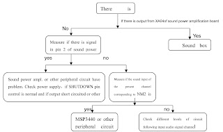
  This model employs double integrated tuner (including high frequency and medium amplification circuits). The signal received by antenna is fed to the main tuner, TUNER1, which contains a high frequency distributor, from which RF signal is shunt to supply to TUNER3 for use. Pin 14 of TUNER1 is for the power supply of high frequency distributor (+5v). Tuners are controlled by auxiliary MCU NM5 (SDA and SCL) to select proper channel and carry out correct switching of systems. After high amplification and medium amplification decoding, video signal and audio signal are output. The output signal of TUNER1 is fed into decoder N102 as the display of main picture whereas the output signal of TUNER3 is fed into decoder N302 as the display of the auxiliary picture for dual picture. Audio signal is directly fed into audio frequency processor NM2 MSP3440. At the same time dual way tuners all send their medium frequency signal of the second sound to NM2 for treatment (used for decoding of stereo or automatic sound volume control). NM2 is provided with the switching over device for audio frequency channels. Audio input of VGA/DVI/YprPb of the main board, after the switching-over as selected by N3, is fed together with the audio signal of TV and AV into NM2, where switching over is selected. The selected audio frequency signal is made use of in the following three ways. One way is, after being subjected to the control of volume and alt and base sound, fed separately through left and right sound channels into sound power amplifier TPA3001 for amplification. Then it is fed into the loudspeaker for sound reproduction. Another way is also fed separately through left and right sound channels into earphone power amplifier NM9 TDA7053 for amplification before being output to earphone socket for listening, of which the volume is controlled by PWM signal produced by pin 50 of NM5.The remaining way is output through video board as AV out.
  Sound power amplifier TPA3001 is an amplification of mono-channel high efficiency D type power. Under the condition of no heat dissipation its output power can be as high as 20 w. It has the functions of over current and overheating protection. Automatic protection comes in when the input to the ground is short-circuited. Then output is stopped. After the removal of short circuit, switch the set again and it restores to normal. Therefore if the set becomes soundless due to the short circuit caused in carelessly pulling out or plugging in the audio frequency wire (it is certainly not recommendable to do so), just switch it on again and no big deal.
PICTURE & IMAGE
  Y signal of AV and SVHS shares the same channel. SVHS has priority. Identification of terminal S is determined by electric level SID fed from SVHS socket to NM5. When the electric level of SID is of high value, the system is identified as SVHS. Signals from TV or AV and YCRCB are altogether fed into digital decoder VPC3230 (sent separately in two ways to N102 and N302). Channel switching is carried out. They are decoded into 16bit CCIR601 signal to be fed into the processor of lower level for treatment. VPC3230 mainly functions to switch over channels, separate Y/C of 4 lines, decoding of colors and adjustment of picture effect.
MAIN CHANNEL
  The digital YCRCB signal in the format of CCIR601 after being decoded in N102 is fed into non-interlace processor N204 PW1230 for treatment from alternate-line into non-interlace. VD1_CLK,VD1_HSYNC VD1_VSYNC, VD1_ACTIVE and VD1_FIELD sent from VPC3230 is used as a key signal to identify modes. If certain channels become abnormal the corresponding pictures will also become abnormal. In addition to the function PW1230 has to process the signal from alternate-line into non-interlace, it can also function to enhance the picture and convert the movie modes 3:2/2:2. The adjustment of brightness and contrast of the main channel is performed by this chip whereas the adjustment of chroma and definition is performed by N102. The digital 24 bit RGB signal output from
PW1230 after treatment is fed into V PORT of N501 PW181 for further processing. The signals of VCLK (clock) and VVS(field synchronization) and VHS(line synchronization) and VPEN(enable signal)are the basic reference for the image processing of lower level.
  For TV set of mono N system, this series has an additional 3D Y/C separation function in the main channel, which is performed by ND02 Upd64083 so as to enhance the quality of the image. In this case the signal flow process of the main channel is different. Video signal and AV/SVHS signal sent from TUNER1 first undergo switching in the switch circuit ND01, then are fed into ND 02 for separation of brightness from color and output as signal Y and C. For N102, no matter whether it’s TV or AV/SVHS, finally the signals are all fed in the form of Y/C into the input port of VIN1and CIN. Yet the setup for the software is somewhat different.
  Auxiliary CPU performs the decoding for the text of main channel or CCD/V-CHIP. Video signal is directly fed to pin 12 of NM5 for decoding. The decoded text or CCD/V-CHIP signal is output in the form of R, G, B, FB and fed into N102 for character superposing.
SUB-CHANNEL
  Signal CCIR601 after being decoded in VPC3230 is directly fed into PW181 G PORT where direct processing is carried out by PW181. The non-interlace processor inside PW181 performs the non-interlace conversion in this channel. Relatively speaking, the efficiency of the internal non-interlace processor of PW181 is lower than that of PW1230. Therefore when displaying dual picture the main picture effect is better than that of sub-picture. The adjustment of brightness, contrast, definition and chroma is performed by N302.
  The decoding of CCD/V-CHIP in this channel is specially performed by 21 line decoder N301 Z86229. The decoded information is superposed onto the image in N302 also in the form of R, G, B and FB.
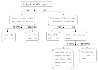
For VGA and YPRPB, after the selection in N1 YPRPB1 and YPRPB2 are fed together with N402 for channel selection. The selected signal is fed into the ADC part of N403 AD9887 for A/D conversion so as to produce 24 bit digital RGB signal to be fed into the G PORT of PW181. The line and field synchronous signal of VGA is directly fed into N403 whereas The line and field synchronous signal of YPRPB is obtained after synchronous separation of Y signal of SOGIN in AD9887 (This signal is input to N403 pin 108).
AD9887 is also provided with DVI input port. The DVI input signal is converted into 48 bit digital RGB signal and sent to G PORT of PW181 for processing. The selection from DVI and VGA/YPRPB is performed by AD9887.Certain organizations for the oversea sales of this TV series have been equipped with the capability to decode HDCP. PORTA4 and PORTA5 of PW181 verify the password (cipher key) through bus line with broadcast equipment. Each TVset has its own independent password, which is stored in EEPROM.
The mode identification of VGA or YPRPB is performed by PW181. The identification process is :
  When selecting channel signal input PW181 presets the synchronous selection of AD9887 so that it can directly output the required synchronous signal for direct feeding to PW181. The synchronous signal format is identified inside PW181. By making cross-reference with the format table pre-stored inside a most similar format is obtained. Then the parameters of this format are called for use in setting up the parameters for modular conversion so that it is optimized. At the same time the conversion coefficient of SCALER is confirmed.
  Finally the video signals of different channels are sent respectively to V PORT and G PORT of main processing chip PW181 for processing. PW181 has such processing capabilities as “picture out of picture”, “picture in picture”, “multiple pictures”. So long as the signals come respectively from V PORT and G PORT, they automatically become “picture out of picture”, “picture in picture”. PW181 has the function of SCALER, which means it can conduct format conversion for the input signals of different format to enable it to meet the requirement of the screen for format and finally output the signal in the form of 24 bit RGB.
  The standard of interface for PDP screen is LVDS (low voltage differential signal). So the digital RGB signal output from PW181 still needs to be converted into LVDS signal by the conversion interface chip of LVDS - N602 DS90C385 (This chip may vary with the manufacturer of the screen). This converted signal is in turn fed to the screen for driving purpose. The output of N602 is four pairs of differential signal and one pair of clock signal. If any pair of signal is abnormal then the image is affected to be abnormal for example, a certain color may become abnormal. The PWRDOWN signal output from PW181 is used to control the operation of N602, which works under low electric level.
  PW181 is also the main CPU. Its program is stored in the externally connected flash N601. The software upgrading of RS-232 is actually the upgrading of the stored memory in N601 by PW181. The interface of menu is also produced by PW181. PW181 can automatically produce self-check signal for troubleshooting.
The above is a short account of the signal flow process of the TV series. Please note HS (Horizontal Synchronous), VS (Vertical Synchronous) and CLK (Clock), PEN (Enable) between individual stages are invariably the basic reference for the mode identification of lower level chip. Make sure that they are in normal working condition.
  PW181 controls the standby of the complete TV set. The POWER-ON signal output from PORTB3 of PW181 is used to control the operation of the power supply board. When it is POWER_ON, the TV set is switched on with low electric level and is in standby with high electric level. When it’s in standby the remaining power supply is only 5VSTBY.
  The voltage VS required by the operation of screen is also controlled by VS_ON output from logic board. It is in operation when the electric level is high. Only when the logic board receives correct signal (clock, synchronous, enable etc.) can VS_ON be correctly output. The operation of PDP screen has very high demand for the time sequence of power supply. If the time sequence is wrong it might make the screen unable to work normally.


PRIMA PS-42D8 B - PS-42D8 S - PH-42D8 - TROUBLE DIAGNOSIS - DISTRIBUTION OF CIRCUIT BOARDS & PART NUMBERS - Universal Remote Controls Setup Codes

$
0
0


PLASMA SCREEN OF 'PS' & 'PH' [TROUBLE DIAGNOSIS]
The screen is not bright:
  • Check to see if the power supply plug from the power filter board to the power supply board is well inserted into the socket. If not, plug it in.
  • Check if the fuse on the power supply board is blown up. If yes, replace it for a good one.
  • Remove our main board and the video frequency processing board, ground the pin 4 POWER_ON/OFF of socket CN802 of the power supply board, and then push the slide switch SW2001 on the logic board to the internal modes (1, 3 up and 2, 4 down) from external modes (1, 2, 4 up and 3down) Switch the power on and see if the screen is lit. If the screen can give a normal and completely white field signal, then the problem lies in our main board or video frequency processing board, which will be dealt with separately.
  • If the screen is not lit, then first replace the power supply board to see if the problem is solved.
  • If the problem remains after the power supply board is replaced, then the problem lies in the screen. Replace the entire screen.
There appears on the screen a line or several unlit lines.
  • Check if the socket between Y driving board and Y BUFFER is plugged well. If not, plug it well. If yes then replace Y BUFFER (upper, lower) in respect to the upper , lower part of the dark line on the screen. 
There appear on the screen one or several horizontal lines that are much brighter than the remaining horizontal lines at the edge:
  • Check if the socket between Y driving board and Y BUFFER is plugged well. If not, plug it well. If yes then replace Y BUFFER (upper, lower) in respect to the upper , lower part of the dark line on the screen.
There appear on the screen one vertical unlit line or a vertical entirely unlit block.
  • If it’s one vertical unlit line, then COF has problem.
  • If it’s a vertical entirely unlit block, then first check if the connection socket between COF and logic BUFFER has problem. If not, check if the connection socket between the logic BUFFER and the logic board is normal. If yes, replace the logic BUFFER. Finally, if the problem still remains when the replacement is over, then replace the logic board.
There appears on the screen a mono color signal and one or several vertical bright lines of other colors:
  • If it’s a vertical bright line of other colors, then the problem lies with COF or the screen.
  • If it’s an entire vertical block of other colors, then first check to see if the connection socket between COF and logic BUFFER has problem. If no problem, check if the connection sockets between the logic BUFFER and the logic board is normal. If it’s normal, then replace the logic BUFFER. If the problem still remains after the replacement, then replace the logic board. Finally if the problem is still there, then the problem lies with COF.
There appear on the screen abnormal bright spots or blocks that are different from what’s described above:
  • Check if the connection socket between COF and logic BUFFER board has been well plugged.
  • Replace the logic BUFFER board. If it’s not solved then replace logic board. If the problem still remains, then it’s the problem with COF.
CIRCUIT BOARDS LAY OUT
42SD-V3(Type: S42 SD-YB03,Code No: 335-42001-00)
42HD-V3 (Type:S42AX-XB01,Code No:335-42002-00)
SIGNAL PROCESSOR BOARDS
PARTS NAME & NUMBERS
CLICK ON PICTURES TO MAGNIFY
SET-UP CODES
GE1019 0165 0116 0167
RCA RCR 311W: 1139
RCA RCR 312W: 10761, 10783, 10815, 10817
RCA RCU 300XP 3643
RCA RCR N04GR: 10761, 11785
RCA RCR 4383: 10761, 10783, 10815, 10817
RCA RCR 311BN: 10761, 10783, 10815, 10817
AR&T UVERSE: 1113
URC 4140: 0055 0032 0287
URC 2054: 10761,10817,11785,1193

PRIMA PH50D8 - PLASMA TV - TROUBLESHOOTING FLOW CHART - UNIVERSAL REMOTE CONTROLS SET-UP CODES

$
0
0


TROUBLESHOOTING CHART
No raster, No picture and No sound: 

Note: Power supply for PDP is provided with over current and over voltage protection functions. If there is over current or over voltage, this protection will function and no output.
SOUND OK, BUT NO PICTURE
  • For the originally self-powered software, if the operation of PW181 is abnormal, in SDA555X there may be a state of individually switched-on. In this case very often the phenomenon of the trouble is there is sound but no image.

Setting up for the self check of the screen:
  • For 42”SD screen (S42SD-YD04):Push down 2 and 4 and push up 3 of SW2001on the logic board;
  • For 50”HD screen (S50HW-XD02):Push down 1 and 4 and push up 2, 3, 5, 6 of SW2001on the logic board;

Make sure resume it to the original status when the check is over.
PICTURE OK, BUT NO SOUND
NO PICTURE TO A/V
First, use dual picture function to judge if the main or sub picture has problem.
NO PICTURE IN SUB-CHANNEL
CLICK ON PICTURES TO MAGNIFY
NO PICTURE IN YPrPb or YCrCb
NO PICTURE TO TV
NO PICTURE TO VGA
DVI - NO PICTURE
If VGA works normally, it’s enough only to check the connection between socket X401and N403 and the operation status of N403. R414 is the matching resistance for its input. If it has problem the DVI image would become abnormal.
ABNORMAL PICTURE
Peculiar color, which may be caused by the following phenomena:
  • A certain differential wire pair of LVDS (RX0+/-,RX1+/-,RX2+/-,RX3+/-,is abnormal, which may lead to lack of color ( it’s not a complete loss of color);
  • Failure with resistor rows R550~R555,which may lead to loss of corresponding color from the gray degree corresponding to the picture of all channels. Through self-signal check by PW181, the failure is still there.
  • Failure with resistor rows R419, R421, R425, R427, R431, R432, which may lead to loss of corresponding color from the gray degree corresponding to the picture of channels VGA/YPRPB/DVI.
  • Failure with resistor rows R415, R418, R422, R424, R429, R430, which may lead to loss of corresponding color from the gray degree corresponding to the picture of channel DVI.
  • Failure with resistor rows R342, R343, R344, R345, which may lead to loss of corresponding color from the gray degree corresponding to the picture of sub-channels TV/AV/YCRCB, or lead to abnormal brightness.
  • Failure with resistor rows R207, R208, R209, R210, R211, R212 or R145, R146, R147, R148, which may lead to loss of corresponding color from the gray degree corresponding to the picture of main channels TV/AV, or lead to abnormal brightness.
  • Bad connection between N203 and N204, which may also lead to abnormal picture (column bar like) in main channel TV/AV.
  • Abnormal picture vertically or horizontally (bar like): Abnormal in complete line extending all the way from up downward on the screen of stand definition TV set; abnormal vertically on half screen of high definition TV set. They may be caused by the damage of the address BUFFER module that directly corresponds to its position, or may be caused by the damage of the connection wire that directly corresponds to the position of the screen. The horizontal bar like abnormality is also related to the Y driving circuit that corresponds directly to its position. To judge these phenomena, It’s possible to check it by setting the screen to the status of self check as explained above.
  • No brightness in the square block area: Normally it’s caused by the damage of the address BUFFER module that directly corresponds to its position, or may be caused by the damage of the connection wire that directly corresponds to the position of the screen. To judge these phenomena, it’s possible to check it by setting the screen to the state of self-check as explained above.
SET-UP CODES [UNIVERSAL REMOTE CONTROLS]
RCA RCR 311W: 1139
RCA RCR 312W: 10761, 10783, 10815, 10817
RCA RCU 300XP 36:  43
RCA RCR N04GR: 10761, 11785
RCA RCR 4383: 10761, 10783, 10815, 10817
RCA RCR 311BN: 10761, 10783, 10815, 10817
AR&T UVERSE: 1113
URC 4140: 0055 0032 0287
URC 2054: 10761,10817,11785,1193
GE1019 0165 0116 0167

PRIMA PS42D8 PLASMA SCREEN - FUNCTIONS OF VARIOUS MODULES - TROUBLES

$
0
0


MODULES & FUNCTIONS
PDP screen can be divided into power supply board, X driving board, Y driving board, logic board, logic BUFFER board (E, F, G), Y BUFFER board ( upper and lower), COF etc.:
  • Power supply board: to supply power for the screen, other functional modules on the screen, our own main board, and video frequency processing board.
  • X driving board: to produce and provide driving signal for X electrode according to the time sequence signal sent from logic board.
  • Y driving board: to produce and provide driving signal for Y electrode according to the time sequence signal sent from logic board.
  • Logic board:to process the image signal sent from the main board, to produce addressing signal and to provide driving signal for X and Y driving boards.
  • Logic BUFFER board (E, F): To convert the data signal and control signal sent from the logic board into the signals required by COF
  • Y BUFFER board (Upper, Lower): to transmit the scanning signal from the Y driving board to the screen, which is divided into upper and lower parts.
  • COF: to convert the signal sent from the logic BUFFER board into the address signal used by the screen.
TROUBLE DIAGNOSIS
The screen is not bright:
  • Check to see if the power supply plug from the power filter board to the power supply board is well inserted into the socket. If not, plug it in.
  • Check if the fuse on the power supply board is blown up. If yes, replace it for a good one.
  • Remove our main board and the video frequency processing board, ground the pin 4 POWER_ON/OFF of socket CN802 of the power supply board, and then push the slide switch SW2001 on the logic board to the internal modes (1, 3 up and 2, 4 down) from external modes (1, 2, 4 up and 3down).
  • Switch the power on and see if the screen is lit. If the screen can give a normal and completely white field signal, then the problem lies in our main board or video frequency processing board, which will be dealt with separately.
  • If the screen is not lit, then first replace the power supply board to see if the problem is solved.
  • If the problem remains after the power supply board is replaced, then the problem lies in the screen. Replace the entire screen.
There appears on the screen a line or several unlit lines.
  • Check if the socket between Y driving board and Y BUFFER is plugged well. If not, plug it well. If yes then replace Y BUFFER (upper, lower) in respect to the upper , lower part of the dark line on the screen.
There appear on the screen one or several horizontal lines that are much brighter than the remaining horizontal lines at the edge:
  • Check if the socket between Y driving board and Y BUFFER is plugged well. If not, plug it well. If yes then replace Y BUFFER (upper, lower) in respect to the upper , lower part of the dark line on the screen.
There appear on the screen one vertical unlit line or a vertical entirely unlit block
  • If it’s one vertical unlit line, then COF has problem.
  • If it’s a vertical entirely unlit block, then first check if the connection socket between COF and logic BUFFER has problem. If not, check if the connection socket between the logic BUFFER and the logic board is normal. If yes, replace the logic BUFFER. Finally, if the problem still remains when the replacement is over, then replace the logic board. 
There appears on the screen a mono color signal and one or several vertical bright lines of other colors:
  • If it’s a vertical bright line of other colors, then the problem lies with COF or the screen.
  • If it’s an entire vertical block of other colors, then first check to see if the connection socket between COF and logic BUFFER has problem. If no problem, check if the connection sockets between the logic BUFFER and the logic board is normal. If it’s normal, then replace the logic BUFFER. If the problem still remains after the replacement, then replace the logic board. Finally if the problem is still there, then the problem lies with COF.
There appear on the screen abnormal bright spots or blocks that are different from what’s described above: 
  • Check if the connection socket between COF and logic BUFFER board has been well plugged.
  • Replace the logic BUFFER board. If it’s not solved then replace logic board. If the problem still remains, then it’s the problem with COF.
For Plasma TVs,  it is best to replace the damaged board with a new one, rather than try to repair it. Be sure to replace it with same part number used.  To some replacements, a software update might be necessary.  So be prepared for that too.

VIEWSONIC - N2751 - 27" LCD TV - SERVICE MODE - PASSWORD - INITIALIZATION - VGA DDC KEY IN PROCEDURE

$
0
0

TO ENTER SERVICE MODE
  • Press ’POWER’, ‘’and ‘ENTER’ at the same time, then go into the FACTORY MODE [SERVICE MODE.]
  • Initialization of EEPROM: Select EEPROM INITIAL and press ENTER. The act of EEPROM INITIAL is completed when EEPROM INIT disappeared.
Initial password: 0000
  • If you forget your initial password, you can press"8866"to resume.
VGA DDC KEY IN
Every time after replacing the main board, you have to do the DDC key in.
If you find the DDC does not conform to the LCD TV, you have to do the DDC key in.
Equipment Needed
  1. N2751W LCD TV
  2. DDC Card
  3. PC
  4. RS-232 cable
  5. Barcode Reader
  6. VGA Cable
  • Connect Power Cord to N2751W LCD TV.
  • Barcode Reader connects with keyboard and PC keyboard port.
  • Connect VGA Card and DDC Card with RS-232 cable.
  • Connect DDC Card and N2751W LCD TV with VGA Cable. (When key in DVI DDC information, use VGA transform to DVI port.)
Key In Procedure
  • Run DDC.exe
  • Choose model number and conform the Time then Press “ENTER” key.
  • When appear the PIC “ choose DDC Card”, Press ALT+2 Enter DDC 2B test interface.
  • Choose DDC Card.
  • Press F8 to choose corresponding model. DAT (N2751W-A.DAT press “ENTER” key)
  • Press F9 to enter the download interface.
  • Key in the serial number or use the barcode reader to scan the barcode of the LCD TV, and press “ENTER” key.
  • The successful picture is as follows. “Compare EDID: OK! Press any key to continue”.
CHECK METHOD
  • Use ViewSonic EDID Editor.
  • Connect the N2751W LCD TV to PC with VGA Cable. Execute the EDID Editor, then Press Ctrl+F5. If the DDC is correct, you can see the information as follow:

VIEWSONIC - N2751 - N2752 - 27" LCD TV - HDMI DDC KEY IN PROCEDURE & FIRMWARE UPGRADE METHOD

$
0
0

HDMI DDC KEY IN
Equipment Needed
  1. N2751W LCD TV
  2. PC
  3. RS-232 cable
  4. Barcode Reader
  5. HDMI Cable.
  • Barcode Reader connects with keyboard and PC keyboard port.
  • Connect DDC Card and N2751W LCD TV with HDMI Cable.
  • Connect Power Cord to N2751W LCD TV.
  • Choose model number then press “ENTER” key.
  • Press “ENTER” key, then the successful picture is as follows. “DDC DOWNLOED OK.
  • Exit program.
FIRMWARE UPGRADE
When you receive the returned LCD TV, please check whether the firmware version is the latest. If not, please do the following procedures to upgrade it to the latest version.
Equipment Needed
N2751W LCD TV
  1. Fixture for Firmware Upgrade
  2. VGA Cable
  3. PC (Personal Computer)
  • Firmware Upgrade Program
  • One additional LCD TV for checking the program execution.

  • Installing the USB device driver. The USB driver will be upgraded if necessary.
  • Insert the USB to RS232 Download Board to PC’s USB port. Then you can found the USB Device detected and follow Windows comments to finish the Driver install.
  • Execute the Mtktool to start download the file. The Mtktool program will be upgraded if necessary.
  • Select Platform : MT8105 , MT1389 or MT8205.
  • Select Baud Rate. 115200x 8 (Suggestion).
  • Enable the USB Bridge.
  • Browsing the File to download.
  • Press Upgrade to download file.
The Baud Rate is auto setting if mismatch found between your platform and Mtktool.
You can slow down the baud rate if some Flash memory can not works properly in high-speed download.

PROFILO TELRA PT-1000 - 26" & 32" LCD TV - SERVICE MODE - MAIN POWER - SCHEMATIC DIAGRAM [Circuit Diagram]

$
0
0


MAIN POWER [SMPS]

CLICK ON PICTURES TO MAGNIFY
SERVICE MODE
  • Press the digits “1923” while the top level Main menu is active.

TCL LCD32V8SY - SERVICE MODE [FACTORY MODE] & SERVICE MENU

$
0
0

SERVICE MODE
  • Press “Vol (-)” button on the remote control to decrease volume to zero.
  • Press “Mute” button make mute icon displays on the right screen.
  • Input the password “9735” in 5S, then factory appears on the left up screen.
TO ENTER SERVICE MENU

  • Press “Vol (-)” button on the remote to decrease volume to zero
  • Press “Mute” button make mute icon displays on the right screen
  • Input the password “3175” in 5S,then Service Menu appears on the centre screen.


VESTEL 17MB37 - SERVICE MODE - SOFTWARE UPDATE - Checking of the New Software - Revert to Old Software Procedure

$
0
0
ANALOGUE PART SOFTWARE UPDATE WITH BOOTLOADER
All file types that used by the bootloader software are listed below:
  1. The Binary File :It has “.bin” extension and it is the TV application. Its size is 1920 Kb.
  2. The Config Binary File :It has “.cin extension and it is the config of the TV application. Its size may be 64 Kb or a few times 64 Kb.
  3. The Test Script File :It has “.txt” extension and it is the test script that is parsed and executed by the bootloader. It doesn’t have to be any times of 64 Kb.
  4. The Test Binary File :It has “.tin” extension and it is used and written by the test groups. It is run to understand the problem part of the hardware.
Alltough a file that is used by the bootloader can be had any one of these extensions, its name has to be “VESTEL_S” and it has to be located in the root directory of the usb device.
USAGE OF THE BOOTLOADER
  • The starting to pass through : The chassis is only powered up.
  • The starting to download something : When chassis is powered up the menu key has to be pushed. Before the chassis is powered up and if any usb device is plugged to the usb port, the programme is downloaded from usb firstly.  Any usb device is plugged to usb port , user must open hyperterminal in the pc and connect pc to chassis via Mstar debug tool and any one of scart,dsub9 or I2c connectors. 
Serial connection settings
Bit per second: 115200
Data bits: 8
Parity: None
Stop bits: 1
Flow control: None
In this case the bootloader sofware puts “C” character to uart. After repeating “C” characters are seen in the hyper terminal user can send any file to chassis by selecting Transfer => Send File menu item and choosing “1K Xmodem” from protocol section.
The Sample Output Before Sending The File
EEProm update.  To Update eeprom content via uart scart,dsub9 or i2c with Mstar tool can used.
Serial connection settings are listed below:
  • Bit per second: 9600
  • Data bits: 8
  • Parity: None
  • Stop bits: 1
  • Flow control: None
Programming menu item is choosed in the service menu and switch “HDCP Key Update Mode” from off to on.
The Programming Service Menu
Then you must see Xmodem menu in the hyperterminal.To download hdcp key press k or to download EEPROM content press w.
If the repeated “C” characters are seen you can transfer file content via select Transfer->Send File and choose “Xmodem”protocol and click the “Send” button.
17MB37 HDCP KEY UPLOAD PROCEDURE
  • Turn on TV set.
  • Open a COM connection using fallowing parameters and select ISP COM Port No
  1. Baud Rate: 9600 bps
  2. Data Bits: 8
  3. Stop Bits: 1
  4. Parity: None
  5. Flow Control: None
  • Enter service menu by pressing “4” “7” “2” 5” consecutively while main menu is open.
  • Select “9. Programming”
  • Select “HDMI HDCP Update Mode” yes.
  • On Hyper Terminal Window press “k”
  • Click on send file under Transfer Tab.
  • Select Xmodem and choose the HDCP key to be uploaded.
  • Press send button
  • Restart TV set.
17MB37 Digital Software Update From SCART
Adjusting DTV Download Mode:
  • Power on the TV.
  • Exit the Stby Mode.
  • Enter the “TV Menu”.
  • Enter “4725” for jumping to “Service Settings”.
  • Select “8. Programming” step.
  • Change “6. DTV Download” to “On”.
  • Switch to the Stby mode.
Adjusting HyperTerminal:
  1. Connect the “MB37 SCART Interface” to SCART1 (bottom SCART plug).
  2. Also connect the “MB37 SCART Interface” to PC.
  3. Open “HyperTerminal”.
  4. Determine the “COM” settings listed and showed below.
Bit per second: 115200
Data bits: 8
Parity: None
Stop bits: 1
Flow control: None
COM Properties Window
  • Click “OK”.
Software Updating Procedure
  • In the HyperTerminal Menu, click the “Connect” button.
  • Exit the Stby Mode.
  • The “Space” button on the keyboard must be pressed, when the following window can be seen.
  • Press the “2” button on the keyboard for choosing “2. Upgrade Application with Xmodem”.
  • Repeating “C” characters are seen in the “HyperTerminal” menu.
The Sample Output Before Sending The File
  • Click the “Send” button on the HyperTerminal
  • Select the “Filename xxxx_slot1.img” using “Browse”.
  • Choose the “1K Xmodem” from “Protocol” option.
Selection of File
File and Protocol Selection Window
In the Software updating Procedure section, when the first “C” character is seen, the filename selection process must be finished before 10 seconds. If the process cannot be finished, the file sending operation will be cancelled. 
The following figure shows this situation.
Capture of Receiving Data Failing
  • When sending the file the following window must be seen.
  • After the sending process the following HyperTerminal window must be seen.
Capture of Sending Process.
Capture of End of The Sending Process.
  • For sending second program file, the Software Updating Procedure must be repeated from the step X. Select the “Filename xxxx_slot2.img” using “Browse”.
  • After sending the second program file, the Software Updating Procedure will be successful.
Note: After the File Sending Process,
  1. Upgrade Application with FUM
  2. Upgrade Application with Xmodem, options must be seen.
End of the Sending Process.
NEW SOFTWARE CHECKING
  1. Turn off and on the TV.
  2. Enter the “Setup” submenu in the “DTV Menu”.
  3. Choose the “Configuration” option.
  4. For controlling new software, check the “Receiver Upgrade” option.
17MB37 - DIGITAL SOFTWARE UPDATE FROM USB
  • Copy the bin file, including higher version than the software loaded in flash, into the USB flash memory root directory. This file should be named up.bin.
  • Insert the USB disk.
  • Digital module performs version and CRC check. If version and CRC check is successful, then a message prompt appears to notify user about new version. If the user confirms loading of new version, upgrade.bin file is written into flash unused slot.
  • Digital module disables the previous software in the flash and then a system reset is performed.
  • After the reset, digital module starts with new software.
REVERT OPERATION
With revert operation, it is possible to downgrade the software.
Revert operation is very similar to upgrade process. In the revert operation, file name should be f_up.bin. Also user confirmation is not asked.
  • Copy the bin file into the USB flash memory root directory. This file should be named force_upgrade.bin.
  • Insert the USB disk.
  • A lower version than the software in flash can be loaded with revert operation. Digital module performs only CRC check. If CRC check is successful, then force_upgrade.bin file is written into flash unused slot.
  • Digital module disables the previous software in the flash.
  • A message prompt is displayed to notify user about end of revert process.
  • Power off/on is required to start digital module with the new software.
For controlling new software, check the “Receiver Upgrade” option.

VESTEL 17PW15 - VESTEL 17PW20 - POWER SUPPLY [SMPS] SCHEMATIC DIAGRAM [CIRCUIT DIAGRAM]

$
0
0

MAIN POWER REGULATOR [SMPS] SCHEMATIC


CLICK ON PICTURE TO ENLARGE

VESTEL 17MB30 - SERVICE MODE - SOFTWARE UPDATE - HDMI EDID KEY UPLOAD - HDCP KEY UPLOAD

$
0
0

SERVICE MODE
To enter service menu by pressing “4” “7” “25” consecutively while main menu is open.
SOFTWARE UPDATE PROCEDURE
ISP Windows Driver should be installed
  • 4 channel cable should be connected to CON5 on ISP apparatus and the other end should be connected to CN117(Next to VGA connector on 17MB30 board. Another option is to use service connector CN108(In front of the tuner). In that case female service connector should be used instead of standard 4 channel cable.
  • ISP aparatus should be connected to PC via USB cable
  • ISP_Tool_V.X.X.exe is executed
  • Click on “Connect” icon located on upper menu tabs
  • An information window should pop-up showing: “Device Type is XXXXXX”. Press OK. If the window does not appear check cable connections and close the ISP_Tool_V.X.X.exe. Disconnect USB cable and reconnect. Restart application and repeat the steps all-over again.
  • To download a binary to PC “Load” tab is used. To upload a binary file to TV “Read” tab is used.
  • Select “Read” Tab from upper menu. Binary file to be uploaded should be specified by clicking “Read” icon.
  • Click on “Auto” Tab. Checkboxes to be selected are shown in image below.  Before starting to upload the file please make sure these adjustments are made correctly. Then click on “Run” to upload the file. While uploading file please do not interrupt. In case of failed upload retry.
HDCP KEY UPLOAD

  • Turn on TV set.
  • Open a COM connection using following parameters and select ISP COM Port No

Baud Rate: 9600 bps
Data Bits: 8
Stop Bits: 1
Parity: None
Flow Control: None
  • Enter service menu by pressing “4” “7” “2” 5” consecutively while main menu is open.
  • Select “9 Programming”
  • Select “HDMI HDCP Update Mode” yes.
  • On Hyper Terminal Window press “K
  • Click on send file under Transfer Tab.
  • Select Xmodem and choose the HDCP key to be uploaded.
  • Press send button
  • Restart TV set.
HDMI EDID KEY UPLOAD

  • Turn on TV set.
  • Connect HDMI cable between TV HDMI port and ISP HDMI port.
  • Enter service menu by pressing “4” “7” “2” 5” consecutively while main menu is open.
  • Select “9. Programming”
  • Select “HDMI DDC Update Mode” ‘YES’.
  • Turn off TV set.
  • Close all running programs.
  • Open MsEEPROM_1.52.exe.
  • Make sure EEPROM 24C02 is selected.
  • Click ”Load File to Table” as shown in below figure then select the file to be uploaded.

  • Select “Write All” from the right hand side menu.
  • Compare File to Table and make sure there is no difference.
  • Repeat steps  for HDMI Port 2.

LG HB905PA – SB95PA-F/S/C/W - SOFTWARE UPDATE - NETWORK UPDATE PROCEDURES

$
0
0


SOFTWARE UPDATE [NETWORK BLU-RAY DISC DVD HOME CINEMA SYSTEM]
  • Burn a DVD recordable disc or USB with a file that is named to “LG_HB_5200B30.ROM”.
  • Insert a upgrading disc or USB.
  • Show help message for disc upgrade as follows.
In the case of Back End program & Front End program 
Press play key to upgrade and it will show progress information.
After completing upgrade then power is off.
NETWORK UPDATE
To update the firmware by connecting your player directly to the S/W update server, your player must be connected to network. If your player is not connected to network, make a physical connection.
  • Press Home on the Remote Control.
  • Press LEFT or RIGHT to select the Setup mode.
  • Select Others =>  Software Update.
  • On the UPDATE window, press “” or “ENTER” to check for the newest update.  (Checking will takes about one minute.)
CautionPressing Enter while checking for the update will end process.
  • If newer version exists, the message “A new update was found. Do you want to download it?” appears.
  • Select OK to download the update. (Selecting CANCEL will end the update.)
  • The player starts downloading the newest update from the SBP server.
  • When downloading is completed, the message, “Download is complete. Do you want to update?” appears.
  • Select OK to start updating.
  • Update will be processed.
Caution : Do not turn off the power during firmware update.
  • When update is completed, the message, “Update is complete.” will appear, and the power will turn off automatically after 5 seconds.
  • Turn the power back on. The system now operates with the new version.

LG HB905PA – SB95PA-F/S/C/W - HOW TO USE THE SA RESET FUNCTION - HOW TO CHECK BD SINGLE LAYER & DOUBLE LAYER DISC

$
0
0


SA RESET
PURPOSE:  In order to insert the new SA adjustment values, it need clearing SA initial values of the flash memory.
REQUIRED SA RESET:
  • After changing Traverse.
  • After changing Main Board Assembly.
  • After changing Main Board Flash IC.
SA RESET PROCEDURE
  • After the set turn on.(then, mode is the home menu).
  • Press HOME key to escape from home menu.
  • Press the 4 => 5 => 6 => 2 => 5 => =>> 0 (numerical button) on the remote controller to display debug window.
  • Select 6 on debug window to perform SA Reset.
  • Press Return key or Pause key to finish debug mode.
  • Playback once BD disc more than 3 seconds.  (At this time, you must use BD ROM single layer and BDR single layer disc.)
TO CHECK THE LAYERS OF DISC

LG HB905PA – SB95PA-F/S/C/W - COMPONENT REPAIR HELP

$
0
0


ABNORMAL MD OPERATION
Abnormal disc reading or abnormal tray open/close. => Replace new MD and test if it is operated normally.
Component
  • Traverse assembly
  • MD junction board
  • FFC cable from main board to MD
Troubleshooting  (Countermeasure)
  1. Check the connection between main board and FFC cable, confirm the connection point.
  2. Check the connection of MD junction board cable.
  3. If all the cable connections are normal, replace the traverse assembly.
After changing MD (Traverse assembly), you must perform "SA Reset". [Refer previous post here]
HB905 series MD Top & Bottom views.
ALL BD DISC READING ERROR
  • All The Blu-ray disc is not operated, but DVD and CD are operated normally.
  • If the LDO for APC of BD laser diode is abnormal, BD doesn't work.
  • If the LD current control is abnormal, BD doesn't work.
Component
  • MD (Traverse Assembly)
  • SIC707 – Adjustable LDO
Troubleshoot
  1. Check MD (Traverse, pick-up) first of all.
  2. Check input/output voltage of LDO SIC707 (12 V, 8 V).
  3. If output voltage is abnormal, check the periphery of SIC707 and replace it.
  4. Check the BD LD Control input/output.  If input signal (LTHR_LPF) is ok But no output (LDI_BD), Check the TR SQ714, SQ716.
ALL DVD DISC READING ERROR
  • All the DVD disc is not operated, but BD and CD are operated normally.
  • If the LD current control is abnormal, DVD doesn't work.
Component
  • MD (Traverse Assembly)
  • SQ712, SQ717
Troubleshoot (Countermeasure)
  1. Check MD (Traverse, pick-up) first of all.
  2. Check the DVD LD Control input / output.
If input signal ( LDELO_LPF) is ok, but no output (LDI_DVD), check the TR SQ712, SQ717.
ALL CD DISC READING ERROR
  • All the CD disc is not operated, but BD and DVD are operated normally.
  • If the LD current control is abnormal, CD doesn't work.
Component
  • MD (Traverse Assembly)
  • SQ713, SQ715
Troubleshoot (Countermeasure)
  1. Check MD (Traverse, pick-up) first of all.
  2. Check the CD LD Control input / output.
If input signal ( LDEL1_LPF) is OK, but no output (LDI_CD), check the TR SQ712, SQ717.
ABNORMAL SERVO OPERATION
  • The actuator, spindle and sled operation of pick-up are abnormal.
  • After changing MD, the motors are abnormal operations.
  • After changing Motor Drive IC, the motors are abnormal operations
Component
  • MD (Traverse Assembly)
  • SIC706 – LM358
Troubleshoot (Countermeasure)
Check if the input/output voltage of SIC706 (Pin5 and Pin7) is 1.67 V
CLICK ON PICTURES TO MAGNIFY

LG HB905PA – SB95PA-F/S/C/W - TROUBLESHOOTING CHART [Click on Charts to Magnify]

$
0
0

SMPS / POWER SUPPLY BOARD
NO SOUND
POWER KEYBOARD
FRONT BOARD
FRONT BOARD [HB965 / HT065]
NO AUDIO CHECK
iPOD AND TUNER FUNCTION
NO VIDEO CHECK
CLICK ON TABLES TO MAGNIFY
HDMI NO AUDIO/VIDEO [HDMI-IN]
HDMI OUT
HDMI NO AUDIO/VIDEO CHECK [WITHOUT HDMI IN]


HOW TO MAKE NETFLIX SETUP & ACTVATION - PROCEEDINGS - FAULTS AND SLUTIONS

$
0
0

NETWORK SETUP  By connecting the unit to broadband Internet, you can use Netflix function

Check the Network
Connection
No
Connect the player’s LAN port to the corresponding port on your Modem Router using a LAN cable. Use a commercially available straight LAN cable (Category 5/CAT5 or better with RJ45 connector)
YES


Configuration Network
Settings
NO
If there is a DHCP (Dynamic Host Configuration Protocol) server on the local area network (LAN), this player will automatically be allocated an IP address. If there is no DHCP server on the network and you want to set the IP address manually, select [Static IP] then set the [IP Address], [Subnet Mask], [Gateway] and [DNS Server] using [IP Setting] option
YES


Checking Network
Configuration
NO

Select [NETWORK] on the [Setup] menu. And then Select [IP Mode] option on the [NETWORK] menu. And then Check the Network status indicator  changes according to Network configuration.

ACTIVATION OF NETFILX ACCOUNT
Activating the unit establishes a connection between the unit and Netflix account.
Netflix member?
NO
Visit www.netflix.com/LG for your free trial. After finishing to join the Netflix, select the [activate] then press ENTER
YES


Entering the activation code
NO
Wait for the activation screen to appear on your TV screen.
On your computer, visit www.netflix.com/activate If necessary, enter your Sign in Name and Password to log into your account. Enter the activation code that appears on your TV screen.
YES


“Congratulations”
screen appears?
NO
Select [get an new code] for retry, Enter the activation
code again on the activation site 


ADDING MOVIE TO YOUR PLAYER
Instant Queue is not empty?
NO
Visit the Netflix website www.netflix.com on your computer. If necessary, enter your Sign in Name and Password to log into your
account. Click [Watch Instantly] tab. When you find a movie or show you want to watch, point your cursor at the [Add/Play] button to reveal additional options, and then click [Add to Instant Queue].
YES


Instant Queue titles < 500 titles
NO
You can add up to 500 titles to your instant Queue, however, we recommend adding 50 or less movies,
so that can easily find what you want to watch.

NETFLIX SERVER ERRORS - ESN [Electronic Serial Number] VALIDATION PROBLEMS - Less Bandwidth and Less Resolution & RECTIFICATION

$
0
0

ESN validation
  • (Select [OTHERS] on the [Setup] menu.
  • And then Select [Netflix] on the [OTHERS] menu.
  • And then Check [Netflix ESN].)

Does it begin with
“LGE-XXXXX-” followed by “8-digit” ?
Example )
BD572 : LGE-BD572-BD592 : LGE-BD592-BD561 : LGE-BD561-HB905 : LGE-HB905-HB965 : LGE-HB965-
NO
If not, the set has a bad ESN (It should not happen) -> replace the player
YES
[Select [Streaming] on the [Home] menu.]
Is it activated successfully?
NO
This means that ESN is valid.
YES


Is Netflix server OK?
NO
If Netflix Server is dead,
activation fails even if the ESN is valid.
YES


Netflix server is OK, but fails in activation.
NO
Call Netflix Customer Support
and check that this ESN
added to the Netflix DB


LESS BANDWIDTH & RESOLUTION
The Quality indicator during movie retrieval corresponds to the following bandwidth requirements:
  • 1.0 Mbps
  • 1.5 Mbps
  • 2.6 Mbps
  • Best quality is 3.8 Mbps

Do you have adequate
broadband connection speed
NO
Recommend a minimum connection speed of 1.5Mbps.
For the best quality picture, a connection speed of 4.0Mbps is required.
YES


Do not have any other online
activity on your network
NO
Your connection may be affected by other activity on your network, such as on-line gaming, file sharing or other video streaming.
YES


Test your bandwidth
NO
You can test your bandwidth at one of these sites:
http://www.speakeasy.net/speedtest/
http://www.speedtest.net/ If you are getting less bandwidth than xpected, you should contact your ISP to troubleshoot.


HOW TO ENTER CENEMANOW FUNCTION - ACTIVATION REQUEST - YouTube

$
0
0

YouTube
Frequent buffering happens while playing videos.
  • Network Condition Meter indicate current network speed between BD Player and YouTube stream server.
  • To play videos without buffering, Network Condition Meter should have more than 3 Bars.


Do you have adequate broadband  connection speed?

NO
Recommend a minimum connection speed of 1.5Mbps. For the best
quality picture, a connection speed of 4.0Mbps is required.
YES


Do not have any Other online
activity on your network?

NO
Your connection may be affected by other activity on your network, such as online gaming, file sharing or other video streaming.
YES


Test your bandwidth
NO
You can test your bandwidth at one of these sites:
http://www.speakeasy.net/speedtest/http://www.speedtest.net/
If you are getting less bandwidth than expected, you should contact your ISP to troubleshoot.


Entering the Cienmanow Function.
(Before using the Cinemanow function, it guides a user network status)

Does It connect to internet?
NO
To enter cinemanow mode, it try to check internet connection.
If failed, it displays the popup message to the user. User can move to [Home] menu or [Network setting] menu as our guideline.

Check the network speed?
NO
If success, it check the network speed from cinemanow server.
Recommend a minimum connection speed of 700kbps for playing titles. If the result of speed check is lower than 700kbps, it displays the warning message to user.
Activation
(To rent or buy titles, a user must activate the player,
Activating the unit establishes a connection between the unit and Cinemanow account)

Request activation code
NO
Visit www.cinemanow.com/activate
If you are not member of cinemanow,press “Get started” button to join the cinemanow. if you are member, sign in.

Step 2
To get the activation code, move to bottom of this page
and press “Continue” A user could change his information though this page. (Payment Information, Adult Access Restrictions)

Step 3
You can see the 5 digit code.
This code only used onetime and is valid within 24 hours.

Entering the activation code
NO
If success,
“Success, Your CinemaNow-ready device is now activated.” is displayed.

HOW TO CONNECT A NETWORK - WHAT IS HOME LINK FEATURE - HOW CAN INSTALL PC BUNDLE PROGRAM FOR {DLNA}

$
0
0

HOME LINK
What is Home link?
  • Home link is a Media File Sharing Function. User can play most of media files in my PC or my NAS ( Network Attached Storage ). General DLNA compatible server shares Media Files on local network.  To connect DLNA server, user must have PC with DLNA server program or NAS with DLNA server certified.  LG gives Home link bundle SW disc(PC DLNA Program for Windows).
  • Another way is to use just file sharing method, this is based on the standard of CIFS (Common Internet File System). User don’t need any program, just set folder sharing on your PC. Home link server search menu can search user-shared folders.

Home link support this media:
JPG,PNG,MP3,WMA,PCM,MPEG1,2,DivX(subtitle support),XviD,MKV,MP4
Other DLNA Servers:
Nero Media home, Cyberlink server, Twonky, Window Media Player11, QNAP NAS etc.
Restrictions:
  • PC and BD Player must be connected in one access point.
  • Anti-Virus program may block media sharing. Before installing SW, stop the Anti-Virus program.
  • LG bundle disc program is Essential program supported by Nero.Inc.
  • Media types support is variable by each DLNA server.
  • DivX subtitle is supported by LG bundle disc only.

What is Home link Feature?

Home link is composed of the screens of selecting server, browsing files, playing video, playing audio, playing photo.  You can move up, down, left, right and select in file browser.
HOW TO CONNECT NETWORK
How can Install PC bundle program for DLNA

Check your network
PC and BD Player are connected to one access point. Check Setup -> Network Status, is it connected normally?


Install PC Bundle SW
Insert bundle CD in your PC and install program. PC Server adds Firewall Exception of nero mdeia server automatically.


Share your media files
Add/Remove PC media folder in share item.


Check “Network Item”
You can check wired or wireless network


Check “Start Server”
Check “Start Server” button.

CLICK ON PICTURES TO MAGNIFY

HOW TO SHARE NEW FILES AND FOLDERS USING-DLNA - HOW MANY DivX SUBTITLE IS SUPPORTED

$
0
0

How to Share new files and folders using DLNA

Add new files and folders
* Double-click the “Nero MediaHome 4 Essentials” icon on the desktop tray.
** Click [Network] icon on the left and define your network name in the [Network name] field. Your player will recognize the Network name you enter.
*** Click [Shares] icon on the left.
**** Click [Local Folders] tab on the [Shared] screen.
***** Click [Add] icon to open the [Browse Folder] window.
****** Select the folder containing the files you want to share. The selected folder is added to the list of shared folders.
******* Click [Start Server] icon to start the server.

Shared folders or files are not displayed on the player
* Click the folder on the [Local Folders] tab and click [Rescan Folder] at the [More] button.
** If you want more information, see Help menu.  Visit the www.nero.comfor more information and software tools.
How many DivX subtitle is supported

Cannot display subtitle
* Check the subtitle file name.
The subtitle file name must match the video file name. For example, the following files will be accepted as subtiles for a given movie.
“Time_Machine.avi” --------video
“Time_Machine.srt” --------subtitle
“Time_Machine.sub” -------subtitle
“Time_Machine.smi” -------subtitle

** Check the subtitle file size. The file size is limited 2Mbytes.
*** Check the subtitle format. Supported subtitle format is as below.
SubRip(.srt/.txt), SAMI(.smi), Substation Alpha (.ssa/.txt), MicroDVD (.sub/.txt), Subtitle System(.txt), Vobsub(.sub/.idx)

One more subtitle files
  • Display priority: If there are several subtitle files in a folder, display priority is this.
Priority:   High  ó  Low
File extension:  “.smi” “.idx” “.sub” “.srt” “.txt” “.ssa”
For example, if there are “Time_Machine.smi” and “Time_Machine.srt” in a folder, “Time_Machine.smi” will be displayed.

Viewing all 2033 articles
Browse latest View live


Latest Images

<script src="https://jsc.adskeeper.com/r/s/rssing.com.1596347.js" async> </script>