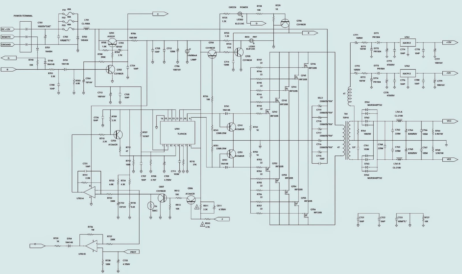
JBL Power supply / Input – Crossover – Power Amplifier _ Schematic (Circuit Diagram)
SPECIFICATIONS
SPECIFICATIONS
Number of Channels . . . . . . . . … 1
4 Ohms . . . . . . . . . . . . . . . . . . …… 600W
2 Ohms . . . . . . . . . . . . . . . . . ………1200W
T.H.D. @ 4 Ohms rated Power . . 0.10%
Frequency Response . . . . . . . . . . 10Hz ~ 320 Hz
Signal to noise Ratio . . . . . . . . . . . >100dB
Maximum Current Draw . …………114A
Fuse size. . . . . . . . . . . . . . . ………… 40A x 3
Input Sensitivity. . …….. . . . . . . . .250mV ~ 4V
Minimum Speaker Impedance…1 ohm
External Dimensions
Length . . . . . . . . . . . . ……………….14 13/16 (376mm)
Width . . . . . . . . . . . . . . . . . . . . . . 10 3/16 (274mm)
Depth . . . . . . . . . . . . . . . . . . . . . . 2 11/16 (68mm)Under certain large signal conditions during intense bass passages, the unit will go into protection. These amplifiers are behaving as designed. As the unit is driven into hard clipping, the protection circuit found in BP Series amps was engineered to protect your loudspeakers from being destroyed by a severely clipped output signal. This can be remedied easily by turning the volume down somewhat on your music source. In the event you receive a BP series amplifier with the complaint: “Under a large signal input, with music that is composed of high-level bass, the amplifier mutes for 2-3 seconds, and then returns to normal operation”, the following modification will effectively increase the amount of clipping that is allowed to occur before the protection circuit engages by increasing the threshold at which the amplifier mutes - for the benefit of customers who use the amps in SPL competition, or for customers who insist on driving the amplifiers into this potentially hazardous zone.
1 Turn the amplifier upside-down and remove the Phillips screws holding the bottom cover on.
2 Locate and change R510 from 47K to 4.7K ohms 1/5W (JBL part# RE212047200).
3 Locate and change R511 from 22K to 2.2K ohms 1/4W (JBL part# QAF0450-222).
4 If it is not already present, add new part - 4.7uf 50v electrolytic capacitor (JLB part# EC070114760) in parallel with R511. Polarity: The negative side of the Capacitor must be connected to the junction of R510/R511, which can be discovered with an ohmmeter.
NOTE: Using the correct soldering techniques, you should be able to make these changes from the top of the PCB without its removal.
5) Replace bottom cover; test amplifier.
POWER SUPPLY SCHEMATIC
INPUT - CROSSOVER - POWER AMP


