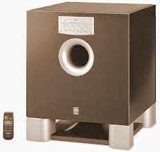
Yamaha YST-SW315 _ Sub-Woofer _ Circuit Diagram & Adjustments [A1145_C2705]
ADJUSTMENTSIdling Adjustment
* To stabilize operation of the amplifier, turn ON the power with no input signal and wait for 2 to 3 minutes in non loaded condition before the adjustment.
* Confirm that the voltage across the terminals TP11 and TP12 is 10 mV to 200 mV. If it exceeds 200 mV, open (cut off) R172.
Confirmation of AUTO STANDBY operation.Setting
# Turn off the power switch located on the rear panel.
# In order to shorten the time required for operation check; connect a 10kΩresistor at both ends of R252 on the MAIN P.C.B.
# Connect the output signal from the signal generator to the INPUT 2 / L/MONO terminal of the unit.
# Set the signal generator for the sine wave of 100Hz, 8mV.
# Turn on the power switch located on the rear panel.
Confirmation
* Set the AUTO STANDBY switch to the LOW position.
* Turn on the STANDBY/ON switch.
* The display LED lights up (green) and its colour changes
* To red after 5 to 10 seconds.
* Turn off the STANDBY/ON switch.
* The display LED goes off.
* Set the AUTO STANDBY switch to the HIGH position.
* Turn on the STANDBY/ON switch.
* The display LED lights up (green) and its colour remains Unchanged even after time has elapsed.
* Turn off the STANDBY/ON switch.
* The display LED goes off.
After confirmation
* Turn off the power switch.
** Disconnect the 10k Ωresistor connected to both ends of R252.
SCHEMATIC [Circuit Diagram] & PWB
Click on the pictures to Magnify


