Samsung WS32Z30 - SLIM CRT TV - Power _ Deflection _ Ass'y Feature box & CRT base card Circuit Diagram.
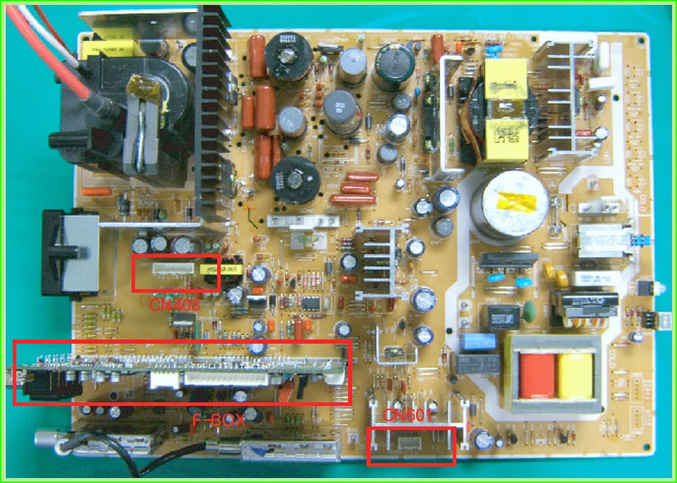
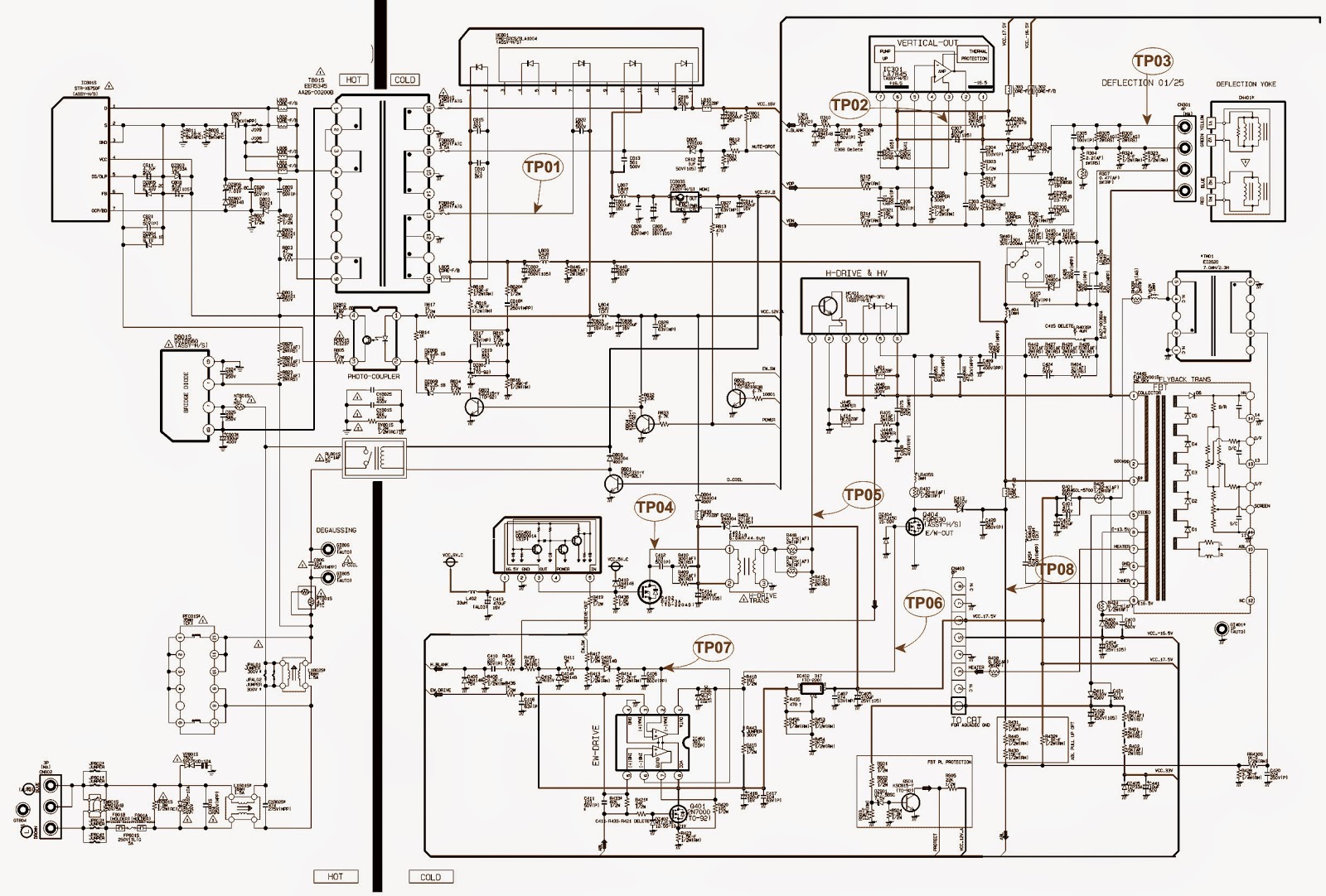
POWER & DEFLECTION ASSY'
CN601 > This is a 4 pin port connected to the Speaker, and sends the signal from the AMP to the speakers.
CN403 > This is a 8 pin port connected to the CRT Board and supplies 200V, +16V, -16V and Heater voltage.
GT804 > This is a ground port to prevent high voltage due to lighting.
CN802 > This is a 3 pin port connected to the AC power cable. It is connected to the power cable socket.
GT805, GT806 > This is a port connected to the D-Coil surrounding the CRT.
SCHEMATIC-SMPS
ASSEMBLY FEATURE-BOX
CN07 > This is a 14 pin port connected to the CRT Assy's, and outputs final R/G/B signals to the CRT Ass'y.
In addition, it outputs the Tilt, VM, and Power signals for the CRT Drive.
CN05 > This is a 4 pin port connected to the Control Ass'y, and receives TV/Video, Menu, Ch Up/Down and Vol -/+ signals.
CN04 > This is a 6 pin port connected to the Master Ass'y, and receives Master Power On/Off, and IR signals.
CN03 > This is a 8 pin port connected to the Side AV, and receives S-Video2 and AV4 external inputs.
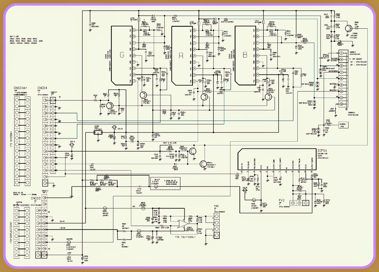
CRT DRIVE CARD
GT501, GT502, GT505, GT506> This is a port connected to the TBC-Wire and plays the role of CRT ground.
GT503, GT504> This is a port for countermeasures against compulsory discharges and is connected to the Main Board.
CNC04> This is a port to receive the R/G/B output signals from the Feature Box.
CNC02> This is a port that receives power for the CRT and AMP from the Main Board.
FV1> A port to connect the VM signal to the DY Ass'y.
FN1> A port to connect signals to the Tilt Coil and is regarded for the screen slant adjustment.
CLICK ON THE PICTURES TO MAGNIFY


