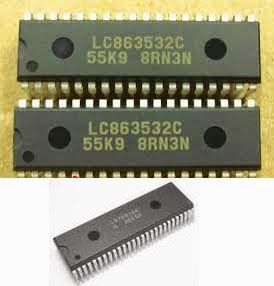
USED ICs: AT24C04/08 (System Memory) – LC86353 (Main System Control) – LA76810 or LA76818A (Horizontal_Vertical_Chroma_VIF _Sync-Seperator Jungle) – AN17821A (Audio Output) – LA78040 (Vertical Output) – BSC24-0144014K / BSC-09N20E LOT)
When switch ON, there is no power light or any other indication. Sometimes, the Power LED may light up, and shut down atonce.
The power supply section circuit to this kit has short circuit protection. By anyway, any short circuit occurs at the main board, the power won’t switch ON. The main cause found to this circuit is with shorted Horizontal Output Transistor [2SD1651C / 2SD2499; (Collector to Emitter or Collector to Base; short). The best way to troubleshoot is, just de-solder out the horizontal output transistor from the PWB, and just switch ON the set, and see whether the Standby Light is ON. If it does, make sure that this transistor is damaged.
Before replacing this transistor, just check for any other reason for its failure. The C435 & C438 should be checked with a capacitance meter for its capacity. It will be best to replace both of them at the same time, along with the horizontal output transistor. Even loose solder terminals at these capacitor terminals will surely make the H-Out transistor get shorted. Check VD435 & VD436 and C437 too. Without checking all these components and its soldering thoroughly, never switch on the set with a new H-Out transistor.
The next possibility for H-out transistor failure is; it’s loose seating screw with the heat sink. Another one is with shorted winding [Horizontal section] of the deflection yoke. Other is HOT [Horizontal Output Transistor; otherwise called as LOT BSC24-01N4014K / BSC25-09N20E. Check all the solder terminals to the leads of this Line out Transformer [LOT] too, for any loose soldering.
If deflection yoke winding has any short (this short can’t be measure by normal technique or with a multimenter); it should be replaced before switch on the set. You can switch ON the set without this deflection yoke connection; but; must unplug the CRT base card from the CRT base; otherwise there is a chance to make a dark spot at the center of the screen due to accelerated beam of electrons inside the CRT, without any scanning. It will fall straight at the center of the screen itself, provided the LOT and H-Out transistor as well as the SMPS is OK. Be sure about this, when you switch on the set without deflection yoke connection. This is true to any CRT based televisions; irrespective of its brand and size.
If the horizontal output transistor is found damaged, check the load resistor R551 2.2Ohms 2W W/W for open. In most cases, this won’t happen to this kind of circuit, as any short circuit occurs at the secondary stage of the SMPS will clause the SMPS to shut down instantaneously.
In practice, this is the most venerable fault that can occur to sets fitted with this kit. 90% of it I did faced was it.
If the LOT is defective (Internal short in its winding), the horizontal output transistor will heat up within seconds. To make this sure, just switch ON the set, and see whether the standby light lights up. If it does, just switch it OFF after 30 or 40 seconds, and unplug the set from AC mains wall socket, and feel the heat of the horizontal output transistor with bare fingers. It can be slightly warm, but not too hot. This effect can due to a damaged deflection yoke too.
It is advised to re-solder all the terminals of IC LA76810 / LA76818A; because this IC will heat up to an extent while the set works, and repeated heating and cooling can make its solder terminals to expand and shrink; and make any loose solder terminals, so microscopic to see with naked eye. It is be best to suck out the solder from each terminal; using a solder suction pump and re-solder it by applying fresh solder, without making any solder bridge short in between. Be very careful. After soldering the IC terminals, clean it using Medical Quality Turpentine or Rectified Spirit.
In most cases, the main system control IC found OK. Do not do any unwanted checks and meter prods touches to it; when power is ON. This is a very sensitive IC; can be damaged easily.
The SMPS circuit to this set is quite simple related to STR based ones, and is easy to follow. I’ve here described some service experiences of mine with this type of kit. There might be more to describe for others. Service experiences to person to person will be different indeed.SCHEMATIC

CLICK ON THE SCHEMATIC TO ZOOM IN