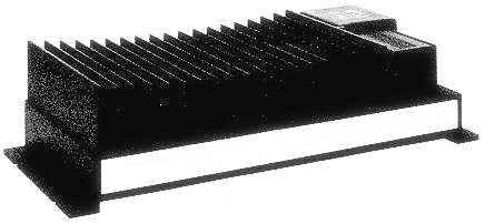
Power Output, RMS
: 60 watts per channel into 4 Ohms, 20 ~ 20,000Hz
: 90 watts per channel into 2 Ohms, 20 ~ 20,000Hz
: 180 watts bridged mono into 4 Ohms, 20 ~ 20,000Hz
Alignment procedure: Idling current adjustment
Conditions:
-Connect the DC voltmeter between TPl and TP2 and between TP3 and TP4.
-Connect a 13. 8V power supply to the 12V Battery
Power In terminal.
-After the power on, wait for 5 minutes before measuring to be sure of the most stable operation.
Inspection:
-Confirm that the idling current is 50mA :t 20mA (voltage: 33mV:t 13mV).
If the current measured does not fall within the range specified , adjust it with the procedure below.
Adjustment
Note: When replacing or disconnecting a resistor, disconnect the power supply first.
After the adjustment is complete, let the unit settle down for 10 minutes, than double-check that the idling current is set properly.
Exploded view
Schematic diagram
Wiring diagram
Protection circuit
If the temperature inside the CA260 rises above 80 the protection circuit comes into operation , decreasing output. At this time the protect indicator blinks. If the temperature comes back below 80 C by natural cooling, output returns as it was.
If the temperature rises above 100 , the power supply circuit is shut off . Not only does the output stop, but also the protect indicator goes out. If this happens, it is possible that the CA260 is broken. However, even in this state, it cannot be always said that it is broken because the unit may operate when the temperature comes back below 80 C by natural cooling.


