Quantcast
Channel: Electro help
Viewing all 2033 articles
Browse latest View live

TCL - DE 200 - LCD TV - HOW TO ENTER SERVICE [FACTORY] MODE - Adjustments - Analogue Board Software Update - MAIN POWER SUPPLY [SMPS] Schematic

$
0
0

SERVICE [FACTORY MODE]
  • Enter the factory menu (can use the IR) and press the remote key [◄V-] to  “0’, press mute remote key, then press 9,7,3,5 remote key.
  • Press [] key to enter the sub-menu and press MENU key to return the main-menu.
ADJUSTMENTS
Adjust the temperature in CMP, VGA, AV.
Make sure the picture mode is set to “Stand”, the “Picture àBlack expand” on the user Menu is set to “OFF”. “Other àFlesh Tone & Adaptive Luma Control ” on
the factory Menu is set to “OFF”. After Alignment, the entire item will change to “ON”
ADC ADJUST
  • For CMP input, the test signal is 576i/50Hz,100%, 8 steps colour bar. Select the “Balance àRGB Calibrate” on the factory Menu, then press “à”, ADC adjust is finished after “OK” is displayed
  • For VGA input, the test signal is 1024×768/60Hz white/black grid. Select the “Balance à RGB Calibrate” on the factory Menu, then press “à”, ADC adjust is finished after “OK” is displayed.
VGA ADJUST
  • For VGA input, the test signal is 1024×768/60Hz 16 steps gray bar. Set the “Balance àTone” on factory menu to “Normal”:
  • For the third step form the white bar, Adjust the value of White R,White G,White B, until the color temperature is x=280±5, y=290±5 Y > 220nit
  • For the second step form the black bar, Adjust the value of GrayR, Gray G, Gray B, until the color temperature is x=280±5, y=290±5 Y < 25nit
  • Repeat, until all is ok
  • Adjust the value of Black level.
AV ADJUST
  • For AV3 input, the test signal is PAL - 8 steps gray bar. Set the “Balance àTone” on factory menu to “Normal”:
  • For the third step form the white bar, Adjust the value of White R, White G, White B, until the color temperature is x=280±5 y=290±5 Y > 220nit
  • For the second step form the black bar, Adjust the value of GrayR, Gray G, Gray B, until the color temperature is x=280±5 y=290±5 Y < 25nit R
  • Repeat A&B, until all is ok
  • Adjust the value of Black level.
CMP ADJUST
  • For CMP input, the test signal is 576i/50Hz-16 steps gray bar. Set the “Balance à Tone” on factory menu to “Normal”:
  • For the third step form the white bar, Adjust the value of White R, White G, White B, until the color temperature is x=280±5 y=290±5 Y > 220nit
  • For the second step form the black bar, Adjust the value of GrayR, Gray G, Gray B, until the color temperature is x=280±5 y=290±5 Y < 25nit
  • Repeat  until all is ok
  • Adjust the value of Black level  
ANALOGUE BOARD SOFTWARE UPDATE
Prepare MTKTOOL UPDATE, update board, serial line.
  1. Connect PC, update board, and J3 on the main board with serial line
  2. Provide the STB +5V for main board
  3. Open “MtkTool.exe” in MTK TOOL program, and set the parameter as below picture.
  4. Press “Browse” for selecting the SW.
  5. Press “Upgrade” to download the SW. It will be OK when it shows “100%”
  6. After downloading SW, it will be long time for Initializing EEPROM.
Procedure - 2
Preparative is same with above.
  • Set SYSTEM > Factory Key on factory MENU to OFF. Connect the device as below picture.
  • Update the SW follow solution- (3), (4), (5), (6)
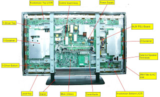
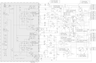
MAIN POWER SUPPLY SCHEMATIC {Click on Pictures to Zoom In}


SANYO - FXWK REMOTE CONTROL - SET-UP CODE LIST & PROGRAMMING PROCEDURE

$
0
0


SET-UP CODE LIST
CLICK ON PICTURES TO ZOOM IN
PROGRAMMING

INSIGNIA NS-LCD37HD-09 _ XOCECO - LC37HV41 – TROUBLESHOOTING CHART - Main Power Supply [SMPS] Schematic (Circuit Diagram)

$
0
0

Before servicing, check to find the possible cause of the fault according to the table below.

Picture is out of focus or jumping
* Bad status in signal receiving
*  Poor signal
*  Check if there are failures with the electrical connector or the antenna.
*  Check if the antenna is properly connected.

Fringe in picture
* Check if the antenna is correctly oriented.
*  Maybe there is electric wave reflected from hilltop or building.

Picture is interfered by stripe shaped bright spots 
* Possibly due to interference from auto-mobile, train, high voltage transmission line, neon lamp etc.
*  Maybe there is interference between antenna and power supply line. Please try to separate them in a longer distance.
*  Maybe the shielded-layer of signal wire is not connected properly to the connector.

There appear streaks or light colour on the screen
Check if interfered by other equipment and if interfered possibly by the equipment like transmitting antenna, non-professional radio station and cellular phone.

Unable to switch the power on
Check to see if the power plug has been inserted properly into the socket.

No picture and sound
* Check to see if the power supply of liquid crystal TV has been switched on. (As can be indicated by the red LED at the front of the TV set)
*  See if it’s receiving the signal that is transmitted from other source than the station
*  Check if it’s connected to the wrong terminal or if the input mode is correct.
*  Check if the signal cable connection between video frequency source and the liquid crystal TV set is correct.

Deterioration of colour phase or colour tone
Check if all the picture set-ups have been corrected.

Screen position or size is not proper
Check is the screen position and size is correctly set up.

Picture is twisted and deformed
Check to see if the picture-frame ratio is properly set up.

Picture colour changed or colourless
Check the “Component” or “RGB” settings of the liquid crystal TV set and make proper adjustment according to the signal types.

Picture too bright and there is distortion in the brightest area. 
* Check if the contrast setting is too high.
*  Possibly the output quality of DVD broadcaster is set too high.
*  It maybe also due to improper terminal connection of the video frequency signal in a certain position of the system.

Picture is whitish or too bright in the darkest area of the picture
* Check if the setting for the brightness is too high
*  Possibly the brightness grade ofDVD player (broadcaster) is set too high.

No picture or signal produced from the display if “XXX in search” appears.
 * Check if the cable is disconnected.
*  Check if it’s connected to the proper terminal or if the input mode is correct.
There appears an indication -                (outside the receivable scope)
* Check if the TV set can receive input signal. The signal is not correctly identified and VGA format is beyond the specified scope.

Remote control cannot work properly
* Check if the batteries are installed in the reverse order.
*  Check if the battery is effective.
*  Check the distance or angle from the monitor.
*  Check if there is any obstruct between the remote control and the TV set.
*  Check if the remote control signal- receiving window is exposed to strong fluorescence.

No picture and sound, but only hash.
Check if the antenna cable is correctly connected, or if it has received the video signal correctly. 

Blur picture
* Check if the antenna cable is correctly connected.
* Of if it has received the right video signal.

No sound
* Check if the “mute” audio frequency setting is selected.
*  Check if the sound volume is set to minimum.
*  Make sure the earphone is not connected.
*  Check if the cable connection is loose.

When playing VHS picture search tape, there are lines at the top or bottom of the picture.
When being played or in pause VHS picture search tape sometimes can’t provide stable picture, which may lead to incorrect display of the liquid crystal TV, In this case press “auto” key on the remote control so as to enable the
liquid crystal TV set to recheck the signal and then to display correct picture signal
NO RASTER
RASTER OK, BUT NO PICTURE
PICTURE OK, BUT NO SOUND [TV-INPUT]
PICTURE OK, BUT NO SOUND [CHANNEL EXCEPT TV]
SMPS SCHEMATIC
CLICK ON PICTURES TO ZOOM IN

PANASONIC - TX-32PS1D - TX-32PS1F - TX-28PS1D - TX-28PS1F - Power Supply [SMPS] Schematic - (STRX6454LF2) - HOW TO ENTER SERVICE MODE - HOW TO ENTER SELF CHECK MODE - DISASSEMBLE - L-Board Schematic - Universal Remote Control Set-up Codes

$
0
0


SELF CHECK MODE
Self-check is used to automatically check the bus lines and hexadecimal code of the TV set. 
  • To enter Self-Check mode, press the STATUS  button on the remote control and at the same time press the down [V-] button on the customer controls at the front the TV set.
  • To exit Self Check, switch off the TV set at the power button.
Self Check mode Display
If the CCU ports have been checked and found to be incorrect or not located then [ - - ] will appear in place of "O.K."
SERVICE MODE
  • Set the Bass to maximum position, set the Treble to minimum position, set the Volume to minimum then press the down button (-/v) on the customer controls at the front of the TV and at the same time press the INDEX button on the remote control, this will place the TV into the Service Mode 1.
  • Press the RED / GREEN buttons to step up / down through the functions.
  • Press the YELLOW / BLUE buttons to alter the function values.
  • Press the TV/AV button after each adjustment has been made to store the required values.
  • To exit the Service Mode, press the "N" button.
CLICK ON PICTURES TO ZOOM IN
DISASSEMBLY
Remove the 11 screws as shown, to remove back cover.
SERVICE POSITION
  • Remove the bead clamper from the mains lead.
  • Hold and lift the rear of the chassis and gently pull the chassis towards you, as shown in Fig.
  • Release the respective wiring clips and rotate the chassis horizontally through 90° anti-clockwise.
SMPS CHEMATIC
AC Mains Filter Section
Switching and Outputs
L-Board
Universal Remote Control Set-up Codes
1164 1167 1211 1163 1431 1411 1146 1144 1488 1273 1012 1021 1154 1246

AKIRA 14RBS3Wn - HOW TO ENTER SERVICE MODE [FACTORY MODE] - FACTORY SET DATA VALUES [Default Data] - Universal Remote Control Set-up Codes

$
0
0

SERVICE MODE
TB 1238 SERIES I2C BUS CONTROL
  • Press the numeric keys, switch to the position 12
  • Press the numeric keys again, switch to the position 38
  • Press the MENU key to call up the POS.LOCK menu
  • Press the MUTE key
  • Press the numeric key to input the password 1, 2, 3, 8
  • Then the TV will enter into the factory mode while the "M" displayed on the top of the screen.
  • Can select the item you want by pressing the ▲▼ keys and can adjust the value of the items when you press the ►◄ keys.
If the adjusting is default, restore the data as previous or adjust according the table as follows:
{Click on Tables to Zoom In}
  • The items with [*] in value are very special, do not adjust them at random. The items (1-5) are used to debug white-black-balance of set.
  • The general secret code is 2175.
  • If you find the threadlike disturbance on the top of picture, please adjust the VM 2 in the items and make its value come to 34.
  • When E PROM does not work, please exchange the same model chip with data that the manufacture has already input. 2.
Universal remote control set-up codes:  1158 1062 1051 1485 1251 1190.

HOW TO PROGRAM RCA UNIVERSAL REMOTE CONTROL - Direct Code Entry - Code Search

$
0
0

APPLICABLE TO:  HC1310, RCU300, RCU300MS, RCU300T, RCU300TMS, RCU300WBL, RCU300X, RCU310, RCU310BB, RCU403, RCU403SP, RCU404, RCU410, RCU410BL, RCU410MS, RCU410W, RCU410WMS, RCU410X, RCU430D, RCU450, RCU4GLW, RCU510, RCU600, RCU600BL, RCU600M, RCU600WMS, RCU800, RCU800B, RCU800MS, RCU800X, RCU807, RCU811, RCU811S, RCU811W, RCU811W, RCU1300, RCU1400, RCUSAT1, SystemLink4, Systemlink3. Models.
Direct code entry method
  1. Press the "CODE SEARCH" button until the indicator light illuminates, then release.
  2. Press and release the device (VCR, TV, Cable etc.) button. If programming for AUX, press and release AUX button first, then press the device type to be programmed. The indicator light blinks and then remains lit.
  3. Enter the 3-digit code number. After you enter a valid three-digit code, the indicator light turns off.
  4. With your device on, press a button (ON/OFF, "PROGRAM UP/DOWN" OR "VOLUM UP/DOWN") to test. If your TV doesn’t respond, repeat the steps above, entering the next code for your brand.
Code search procedure
  1. Press the "CODE SEARCH" button until the indicator light illuminates, then release.
  2. Press and release the VCR, TV or Cable button. If programming for AUX, press and release AUX button first, then press the device type to be programmed.
  3. Press "ON/OFF" repeatedly until the device turns off. Note that because there are so many codes, you may have to press the "ON/OFF" button a few hundred times if your code is towards the end in the list.
  4. When your device shuts off, press and release the "ENTER" button.
  5. With your device on, press a frequently used button like "PROGRAM UP/DOWN" OR "VOLUM UP/DOWN" to test. 
  6. If it does not function correctly, repeat steps 1 through 6.
Auto code search method
  1. Turn on the device you want the remote to operate.
  2. Press and hold the "CODE SEARCH" button until the indicator light illuminates, then release.
  3. Press and release the device key that corresponds to the equipment you want the remote to operate (TV, VCR/DVD or DBS/CABLE etc.). The indicator light blinks once and then remains lit.
  4. Aim the remote at the device and press the ON/OFF key once. The remote automatically sends every code for the specified component one at a time, with a a few seconds delay between each code. Keep the remote aimed at the component throughout the process.
  5. As soon as the component turns off, you must press the "ENTER" button immediately for the remote to store the correct code. If you don't press "ENTER" within a few seconds, the remote will send the next code in the list and you will have to start over from Step 2.
Use Code Retrieval described below to identify the code for your device for future reference.
Code retrieval procedure
  1. Press and hold the "CODE SEARCH" button until the indicator light turns on, then release.
  2. Press and release the device key that matches the equipment's code you are retrieving (TV, VCR/DVD, DBS/CABLE, etc.). The indicator light will blink once then remains lit.
  3. Press and release the "CODE SEARCH" key. The indicator light will turn off.  Starting with 0, press the number keys in order (0-9) until the indicator light blinks.
  4. The number that causes the indicator light to blink is the first digit of your code.
  5. Repeat Step 4 until you have retrieved all 3 numbers of your code.
Sleep timer adjust
  • Press and hold the "SLEEP" key, then release. The indicator light will stay lit.
  • Enter time in minutes using the numerical keypad (from 1 minute to 99 minutes). For 1 to 9 minutes press 0 before the actual number. The indicator light will go off. Leave the remote aimed at the TV set.
  • The Sleep timer program can be cancelled (reset to zero) by pressing and holding the "SLEEP" button until the INDICATOR LIGHT blinks or by pressing the ON/OFF button.
        For set-up code list, check this.

PHILCO TP14U56 / TP14U56B / TP20V56 / TP29C21 - POWER SUPPLY [SMPS] SCHEMATIC [Circuit Diagram] - Universal Remote Control Set-up Codes

$
0
0


SMPS SCHEMATIC
CLICK ON PICTURES TO ZOOM IN

Universal remote control set-up codes
    GE REMOTE CONTROL => 0062 0004 0005 0009 0183 0068 0075 0141 0003 0008
    RCA RCR 311W => 1002, 1004, 1009, 1014, 1025, 1046, 1051, 1053, 1054,1060, 1061, 1062, 1066, 1067, 1072, 1073, 1074, 1076, 1077, 1078, 1082, 1083, 1085, 1091, 1133, 1205, 1230

    Others => 1052 1217 1190 11451080 1239 1007 1039 1157 1051 1171 1012 1310 1326 1141 1219 1024 1046 1081 1136 1287 1298

HOW TO ENTER SERVICE MODE TO RCA & GE TELEVISIONS - Universal Remote Control Set-up Codes

$
0
0


SERVICE MODE ENTRY & ADJUSTING PARAMETERS
For most models after 1994:
  • Turn the TV on.  
  • Press & Hold down MENU and hit POWER and Volume +.
  • Now you're in the service mode, looking at parameter 0.
  • It will say: P00 V00
  • Use the Volume + key to change the value (V number) to 76. This has to be set before you can do anything else; it's sort of a password.
  • Once P00 is set to V76 you can use the Channel ▲/▼ buttons to select from the first 12 parameters.
  • P13is another password – set to 77 to get higher parameters.
  • Depending on the model, another one a couple of dozen parameters up will require a password of 78.
  • This varies by model but you will know when you have found it because you won't be able to advance past it.
  • The first parameter, P01, is probably the quickest and easiest to work.
  • It is the Horizontal Frequency control. When you select it, the TV will lose horizontal sync.
  • Turn it all the way down or all the way up with  [►V+]  or [◄V-] and then get out of set-up (if the TV hasn't shut itself off) then switch OFF the power button.
The parameter tables:
P00 => Password (Must set to 76) P14 PLL Tuning
P01 => Horizontal Frequency P15 4.58 MHz Trap
P02 => Horizontal Phase P16 Video Level
P03 => EW DC (Width) P17 FM Level
P04 => EW Amplitude P18 B+ Trim
P05 => Vertical DC P19 RF AGC Chan 6
P06 => Vertical Size P20 RF AGC Band 1
P07 => Red Bias P21 RF AGC Band 2
P08 =>Green Bias P22 RF AGC Band 3
P09 => Blue Bias P23 D-PIP Chroma
P10 => Red Drive P24 D-PIP tint
P11 => Green Drive P25 D-PIP bright
P12 => Blue Drive P26 D-PIP contrast
P13 => Password (Must set to 77) 

P27 => Factory Tint
P28 => Password (Must set to 78)
P100 =>156

Universal remote control set=up codes
With GE Remote control to RCA TV => 0031 0004 0048 0054 0094 0100 0102 0107 0129 0191 0005 0009 0000 0162 0163 0342 0003 0015 0022 0096 0113 0125 0179 0187 0188
With GE remote control to GE TV => 0031 0107 0164 0004 0009 0044 0054 0000 0342 0003 0125 0015 0022 0052 0087
With RCA RCR311W remote control to RCA TV => 1000, 1002, 1004, 1005, 1014, 1025, 1078, 1081, 1095, 1096, 1097, 1098, 1099, 1100, 1101, 1111, 1128, 1130, 1132, 1134, 1144, 1146, 1149, 1171, 1205
With RCA RCR311W remote control to GE TV => 1000, 1002, 1004, 1017, 1050, 1052, 1078, 1086, 1098, 1120, 1132, 1197, 1207
With RCA 312W remote control to RCA TV => 10000, 11447, 10051, 10093, 10679, 11047, 11147, 11247, 11347, 11781, 12002, 12187
With RCA 312W remote control to GE TV => 11447, 10000, 10051, 10451, 10178, 10021, 11347

6-IN-One remote control to RCA TV
013,016,017,018,020,022,109,111,112 113,114,115,116,142,192,194,200,201
6-IN-One remote control to GE TV:  113,016,017,022,035,065,067,068,100,176,177,178,179,180,181,194
Others to GE TV: 1180 1215 1288.


AKAI PDP 5006M - MODULES AND FUNCTIONS - FAILURE SYMPTOMS & SCREEN-SHOTS - Universal Remote Control Set-up Codes

$
0
0

MODULE
There are 1 pc. panel and 12pc.s PCB including 2 Pac’s Y/Z Sustainer board, 2 Pac’s Y Drive board, 6pc.s X Extension boards, 1 pc. Control  (Signal Input) and 1 pc. Power board in the Module.
SET
There are 6pc.s PCBs including 1 pc. AUX. PSU Board, 1 pc. Keypad board, 1 pc.  Remote Control Receiver board, 1 pc. L/R  Speakers and 1 pc. Main (Video) board in the SET.
PCB FUNCTION
Power:
  • Input voltage: AC 110V~240V, 47Hz~63Hz.  Input range: AC 90V(Min)~265V(Max) auto regulation.
  • To provide power for PCBs.
  • Main (Video Interface) board: To converter TV signals, S signals, AV signals, Y Pb/Cb Pr/Cr signals, DVI signals and D-SUB signals to digital ones and to transmit to Control board.
  • Control board: Dealing with the digital signal for output to panel.
Y-Sustainer / Z-Sustainer board:
  • Receiving the signals from Control and high voltage supply.
  • Output scanning waveform for Module.
  • Y-Drive board: Receive signal from Y sustainer, output horizontal scanning waveform to the panel.
  • X extension board (6pcs): Output addressing signals.
  • Tuner/Audio Board: Process and Amplifying the audio signal to speakers and convert TV RF signal to video/audio signal and send to Main board.
PCB FAILURES
CONTROL:
  • Abnormal noise on screen.
  • No picture.
MAIN (video):
  • Lacking color, Bad color scale.
  • No voice.
  • No picture but with signals output, OSD and back light.
  • Abnormal noise on screen.
POWER:
  • No picture, no power output.
Z Sustainer:
  • No picture.
  • Color not enough.
  • Flash on screen.
Y-Sustainer:
  • Darker picture with signals.
X-Extension :

  • Abnormal vertical noise on screen.
Audio Board or AUX PSU:
  • No voice. (Make sure Mute/OFF)
  • Noise.
Defect: Address (vertical stripe) Open.
  • A line or block does not light up in address electrode direction. (1 line ,block open).
Cause
Manufacturing : Panel electrode single line/foreign material./electrostatic/TCP defect
Parts : TCP, Board connection defect
Operation : Assembly error/ Film damage.
Defect: Address (vertical stripe) Short.  Another color simultaneously appears because adjacent data recognizes the single pattern signal.
Cause: Manufacturing : Panel electrode short / Foreign material conductive foreign object inside TCP
Part : TCP/buffer defect lighting electrode cutting defect.
Defect: Address output error.  A defect other than address open and short Data printout signal error occurring at certain Gradation or pattern.
Defect: Sustain (horizontal stripe) Open.  One or more line do not light up in Sustain direction.
Cause: Manufacturing: Panel bus electrode single line FPC pressure defect.
Parts : FPC/board/connection disconnection
Operation : assembly error.
Defect: Sustain (horizontal stripe) Short.  Combined or adjacent lines are short in sustain direction. The line appear brighter than other at Ramp gradation pattern or low gradation patter.
Cause: Manufacturing: Panel electrode short/Foreign material.
Parts: Board/ connector/pin error
Operation: connector / assembling error.
Defect: Dielectric material layer damage.
Symptom: Burn caused by the damage of address bus dielectric layer appears in the panel discharge/non discharge area. Sustain also open/short occurs by the damage of address sustain printout.
Cause: layer uneven / abnormal voltage/ foreign material repair failed.
Defect: F/White low discharge.
Symptom: Low discharge caused by unstable cells occurring at full white pattern if high (60 degree) or normal temperature.
Cause:
Panel :  MgO source / dielectric thickness cell pitch/phosphor
Circuit : drive waveform/ voltage condition.
Defect: panel damage.
Symptom: Panel crack or break. No image appears in some cause depending on the damaged parts and damage level.
Cause
Manufacturing: Flatness/palette pin interruption
Operation: overload of panel corner / careless handling
Panel: Flatness / assembly error.
Defect: Exhaust pipe damage.
Symptom: Crack in break if exhaust pipe an image is partially lacking or the panel noise occurs depending on the damaged parts and with the passage of time.
Cause: Careless panel handling.
Universal Remote Control Set-up Codes to Akai TVs
1134 1052 1204 1201 1157 1203 1132 1075 1061 1003 1210 1231 1019 1054 1051 1203 1077 1014 1314 1007 1172 1031 1072 1274 1160 1285 1162 1035 1349 1433 1243 1012 1140 1190 1144 1091 1141 1288 1184 1109 1351 1311 1341 1342 1211

ORION 21MT9A - How to enter Service Mode - HOW TO UNLOCK HOTEL MODE - CONFIRMATION OF USING HOURS - REPLACING MEMORY IC - Universal Remote Control Set-up Codes

$
0
0


To enter the Service Mode, press both set key and remote control key for more than 1 second.
 HOTEL MODE
  • Press and hold the CHANNEL  button on the TV, and press the POWER button on the remote control simultaneously.
  • Press the SET +/– button to select the HOTEL LOCK ALL CLEAR mode, then press the ENTER button.
  • The "OK" indicator appears for 4 seconds on the screen.
CONFIRMATION OF USING HOURS
POWER ON total hours can be checked on the screen. Total hours are displayed in 16 system of notation.
The confirmation of USING HOURS does not function if the clock has been set.  If so, unplug AC cord to set the clock to the unlock setting mode.
  • Set the VOLUME to minimum.
  • Press both VOL. DOWN button on the set and Channel button (6) on the remote control for more than 1 second.
  • After the confirmation of using hours, turn off the power.
MEMORY IC REPLACEMENT
  • If a service repair is undertaken where it has been required to change the MEMORY IC, the following steps should be taken to ensure correct data settings while making reference to TABLE.
  • The confirmation of USING HOURS does not function if the clock has been set.  If so, unplug AC cord to set the clock to the unclock setting mode.
  • No need the setting for after INI F3.
Click on Pictures to Zoom In
  1. Enter DATA SET mode by setting VOLUME to minimum.
  2. Press both VOL-DOWN button on the set and Channel button (6)on the remote control for more than 2 seconds.
  3. ADDRESS and DATA should appear as FIG.
  4. ADDRESS is now selected and should "blink". Using the SET + or - keys on the remote, step through the ADDRESS until required ADDRESS to be changed is reached.
  5. Press ENTER to select DATA. When DATA is selected, it will "blink".
  6. Again, step through the DATA using SET + or - until required DATA value has been selected.
  7. Pressing ENTER will take you back to ADDRESS for further selection if necessary.
  8. Repeat steps 3 to 6 until all data has been checked.
  9. When satisfied correct data has been entered, power OFF the set, or return to Standby mode.  The unit will now have the correct data for the new memory IC.
Universal remote control Set-up Codes
Orion [Hungary] => 1052 1012 1289 1059 1051 1104 1075 1049
Others => 1083 1102 1104 1206 1061 1051 12031107 1055 1087 1056 1189 1065 1274 1182 1422 1091 1132 1157 1106 1008 1052 1337 1210 1021 1158 1075 1105 1287 1173 1201 1004 1251
With GE Universal Remote control => 0121 0135 0035
With RCA RCR 311W Remote control => 1020, 1030, 1054, 1056, 1133, 1167, 1230
With RCA RCR 312W Remote control => 10236, 10463, 11463
With 6-IN-1 Universal remote control => 048

LG DV140 - LG DV140P & LG DR 4812W HDD DVD - POWER SUPPLY SCHEMATICS [Circuit Diagrams] - Universal Remote control Set-up Codes

$
0
0

LG DR 4812W HDD DVD POWER SUPPLY SCHEMATIC
LG DV140 - LG DV140P POWER SUPPLY SCHEMATIC
Click on pictures to Zoom In
Universal Remote control Set-up codes
2024 2101 2307 2072 1042 1288 2382 2307 2327 2307 2327 2342

SHINCO - DVD-2610 - MAIN POWER REGULATOR - SCHEMATIC DIAGRAM [Circuit Diagram] - Universal Remote Control Set-up Codes

$
0
0

POWER SUPPLY SCHEMATIC DIAGRAM
PCB
Click on pictures to Zoom In
Universal Remote control Set-up  codes
With GE Universal Remote control:  0430 & 430

SANYO CP21CE1 - HOW TO ENTER SERVICE MODE - SERVICE ADJUSTMENTS - Universal Remote Set-Up codes - Power Shut-Down - Main Power Supply [SMPS] Schematic

$
0
0

SERVICE ADJUSTMENTS AFTER REPLACING THE MEMORY IC
Initializing Procedure
  • Put a new memory IC.
  • Turn on the TV set.
  • Press and hold the TV/AV Selector on the TV set for more than 2 seconds.
  • The following picture appears on the screen.
  • Press the PROGRAMME UP on the TV set while the above On-Screen Display is still on the screen. The following picture appears on the screen.
  • Switch off the TV set by pressing the Power Switch button on the TV set while the above On-Screen Display is still on the screen.
  • This completes the initialization of memory IC.
Following shows the initialized contents of memory data by this procedure.
Plug & play : No executed
Inhibit data : Cancelled
Ch skip data : Cancelled
Sound volume data : 10/63 steps.
Volume Lock  : OFF
Colour system : AUTO
TO ENTER SERVICE MODE
  • Press and hold the MENU button on the Remote Control and press the VOLUME (+) button on the TV set.
  • Following setting items appears on the screen.

  • Select item by pressing the TIMER (Item No. UP) or SOUND MUTE (Item No. DOWN) button on the remote control handset.
  • Adjust data value by pressing the VOLUME +or VOLUME -button on the remote control handset.
  • To return to normal TV mode, press the MENU button on the TV set or the remote control handset.
Power Shut-Down Problem. Releasing the protective circuit and restoring power supply
  • To release the protective circuit and restore power supply, turn the power to the TV set OFF and then ON again via either the main power switch or the ON-OFF button on the remote control. This will work only if the power supply trouble was temporary. If there is permanent trouble such as a damaged circuit, power cannot be restored and the circuit will have to be repaired.
SMPS Schematic
Click on pictures to Zoom In
Universal Remote Set-Up codes
3 digit: 416 017,062,063,093,120,121,182,193
Four digit: 1073 1079 1069 1072 1145 1423 1061 1178 1047 1171 1298 1316 1347 1349 1143 1157 1172 1208 1360 1024 1115 1052 1232 1046 1047, 1078, 1080, 1121, 1129, 1163
Five digit10054, 10154, 10159, 11142

SANYO CM21LX8BC – CM21LX8CA – CM32MX8ZCA – CM21MX8 & CP21CE1 A6 - MAIN POWER SMPS - SCHEMATIC DIAGRAM

$
0
0

CM21LX8BC - CM21LX8CA - CM21MX8 -  CM32MX8ZCA [SMPS] Schematic
CP21MX8 [SMPS] Schematic
Click on Pictures to Zoom In.

MARANTZ - CD-7300 - SERVICE MODE - ERROR CODE DISPLAY - Emergency Eject

$
0
0

SERVICE MODE
  • While pressing DISPLAY and QUICK REPLAY buttons, press POWER button.  Mode0 (Display :   Ver : P00 Version number of the micro computer is displayed).  Status: [FOCUS OFF] [SPINDLE OFF] [RADIAL OFF] [MUTE ON]
  • While pressing ►► and ◄◄ buttons, the sledge  moves toward the outer edge.  Release the button makes the sledge return to the origin.
  • Press EASY JOG or NEXT ►►| button on the remote to go to Mode 1.
Mode 1 (Display : Ver : P01). Status: [FOCUS ON] [SPINDLE OFF] [RADIAL OFF] [MUTE ON].
  • Press NEXT ►►| button to go to Mode 2.
  • Press PREV |◄◄ button to go to Mode 0.
Mode 2 (Display : Ver : P02).  Status: [FOCUS ON] [SPINDLE ON] [RADIAL OFF] [MUTE ON]
  • Press NEXT ►►| button to go to Mode 3.
  • Press PREV |◄◄ button to go to Mode 1.
Mode 3 (Display : Ver : P03).  Status: [FOCUS ON] [SPINDLE ON] [RADIAL ON] [MUTE OFF]
  • Press PREV |◄◄ button to go to Mode 1.
  • In this Service Mode, all of the following button functions work in any status.
  1. Press DISPLAY button to light up all the FL segments. Press it again then each FL segment lights up one by one.
  2. Press STOP button. Then press a button on the unit. The name of the button is displayed. Pressing a button on the remote displays the RC-5 code of the button.
  3. Press PLAY button in Mode 1, 2 or 3 then normal operation can be performed. If an error occurs the error number is displayed.
Terminating Service Mode
Turn off power to quit Service Mode.
ERROR CODES & DETAILS
DISASSEMBLY
Emergency Eject
  • To open the stucked tray, insert a pin into the eject pinhole and push the eject lever.
  • Use a pin φ 4mm or less.
This picture shows the unit upside down. The eject lever is pointed by the arrow.  The lever is thin so aim the narrow area carefully.
When removing the flat wire PS01, connecting the optical pick up and the CD decoder board, short-cut the two lands pointed by the arrow with solder. Otherwise the laser diode may be damaged by static electricity.
CD Decoder Board (PS01) Repair
When Repairing the CD decoder board PS01, you can fix the board on the loader unit as shown in the picture below with the flat wires that are provided as service parts.
Disk Tray Open/Close Speed Adjustment
  • Open/Close speed of the tray can be changed.
  • When vibration occurs upon tray open/close and some unusual behavior happens, change the tray speed to stop vibration.

Vibration on Disc Tray Open / Close
Step 1.  With pressing DISPLAY and QUICK REPLAY buttons, press POWER button.
Step 2.  Press EASY JOG button. “T-OnTime 015”(means Tray On Time 015ms default) is displayed.
Turn n EASY Jogtrot change tray open/close speed from 000 to 255ms. Turn the number smaller to make the open/close speed slower. Turn the number bigger to make the speed faster. Set bigger number to stop the tray vibration. But the open/close speed becomes faster. Press EASY JOG button again.
The display changes as shown below so you can change other parameters for the open/close speed.
Step 3.Press EASY JOG button to complete adjustment.
Step 4.Press STOP button to store the settings in memory.
To reset all the settings to default status, press number 0 button in Service Mode 0  (Display : Ver   P00).
When miss-operated, press number 0 button to retry.
{Click on pictures to Zoom In}


SCHEMATIC DIAGRAM - MARANZ-CD7300 - HEADPHONE AMPLIFIER - PRE AMPIFIER - POWER SUPPLY

$
0
0

FULL CIRCUIT
CLICK ON SCHEMATICS TO ZOOM IN
SECTION-WISE
HEADPHONE AMP & POWER SUPPLY

SANYO LCD 32K30 - HOW TO ENTER SERVICE MODE - White Balance Adjust - Main Power Regulator [SMPS] Schematic Diagram

$
0
0

SERVICE MODE
This set has an On-screen Menu system included in the CPU that allows remote operation for most of the service adjustments.
  • Press and hold the MENU button on Side Controls.
  • Keep pressing the MENU button and press “1”button on the remote control, and the FACTORY MENU will be displayed.
  • Select “DATA” line by pressing or button.
  • Press ◄► button to adjust data.
  • Press MENU button to exit service mode.  The all adjusted data in service mode will be memorized into EEPROM automatically.
WHITE BALANCE
  • Enter the Service Mode.
  • Select "Source ALL" by pressing button, and select "Properties White" by pressing ◄►button.
  • Set R, G, and B value to “FF” by pressing NUMERIC buttons. 
  • After adjustment, confirm white balance again by normal picture Exit the Service Mode
  1. To adjust Red: Press 1 (data value up) and 4(data value down).
  2. To adjust Green: Press 2 (data value up) and 5 (data value down).
  3. To adjust Blue: Press 3 (data value up) and 6 (data value down).
Decide one item in three items to a fixed value (For example, let Rbe fixed value), select item of other 2 colours.
(Example, Gor B), and adjust to produce a normal black and white picture in highlight areas.
(Note: At this time, adjust the other 2 colours data less than fixed data.)
SMPS SCHEMATIC
{CLICK ON PICTURES TO ZOOM IN}
PCB-FOIL SIDE
Universal Remote Control Set-up Codes
GE REMOTE: 0049 0097 0110 0004 0268 0012 0108 0180 [625, 705]
RCA RCR 311W: 1047, 1078, 1080, 1121, 1129, 1163
RCA RCR 312W: 10054, 10154, 10159, 11142
6-in 1 Super remote: 017,062,063,093,120,121,182,193
Others: 1072 1145 1423 10611178 1047 1171 1298 1316 1347 1349 1143 1157 1172 1208 1360 1024 1115 1052 1232 1046

NORCENT LT-2722 - POWER SUPPLY SCHEMATIC [CIRCUIT DIAGRAM] - Password Reset - Factory Mode [Service Mode] - Universal Remote Control Set-up Codes

$
0
0

MAIN POWER SMPS SCHEMATIC
SUB-POWER SCHEMATIC
{CLICK ON PICTURES TO ZOOM IN}
COMPONENT SIDE
FOIL SIDE

PASSWORD RESET
Change the password (default is ‘1111”).
Follow the instructions on the screen. Once changed, please remember your own password. If you have forgotten your password, please do the following:
  • “POWER (OFF) = MENU => V-CHIP => MUTE” to revert to the default password of 1111.
FACTORY MODE
  • Press Number key 100 => 9 => 9 => 1 into Engineer Mode.
  • Press menu key repeat to “ADC “page, then select “EPinit” and press “right” key to initial EEPROM.
  • Press Number key 100 => 9=> 9 => 9 into the Factory Mode.
Turn the POWER-button off to on to quit from factory mode.

Universal Remote Control Set-up Codes
GE : 0216 0043 0056 1027 [043, 216]
RCA RCR 311W: 1203 1207, 1222
RCA RCR 312W: 10748, 10824 11610, 11144, 11240, 11331

ACER ASPIRE 4920 - HOW TO BYPASS PASSWORD - BIOS RECOVERY

$
0
0

PASSWORD BYPASS
Operation Procedures of Password Bypassing and BIOS Recovery.
For RD and CSD to debug easily, the system provide one hardware DIP switch for Bypassing Password
Check, and one Hotkey to enable BIOS Recovery.
DIP Switches
DIP => SW1
Default Setting => Disabled (High)
Description => Bypassing Password Check.
Bypassing Password Check (SW1):
If the user has set Password (power-on or set-up password) for security reason, BIOS will check password during POST or when entering the BIOS set-up menu. However, if it is necessary to ignore the password check, the user may enable DIP SW1 to bypass password check.  BIOS Recovery: Boot Block is a special block of BIOS. It is used to boot up the system with minimum BIOS initialization. The user can enable this feature to restore the BIOS to a successful one if previous BIOS flashing process fails.
DIP Switch Location:

RD/CSD can enable or disable this function by switching the DIP. The Dip switch is located as shown in the figure below:
Clear Password
DIP SW1: Bypassing Password Check is disabled by default. Switching into ON then powering on the system will force the BIOS to clear Supervisor and User passwords. The power-on, set-up password, and the HDD password are all cleared.
[Short R525 to clear password.]
Restore BIOS by the Crisis Disk
Enable this function by pressing the combination: Fn+ESC, and pressing the Power Button. To use this function, it is strongly recommended that the AC adapter is connected to the system and plug-in to a wall outlet and the Battery is also in the system. If this function is enabled, the system will force the BIOS to enter a
special BIOS block, called BootBlock. RD/CSD can use this special BIOS code to recover the BIOS to a successful one if previous BIOS flashing process fails. However, before doing this, one Crisis Disk should be prepared in WinXP. Detailed steps are as the followings:
  • Prepare the Crisis Disk in WinXP
  • Insert the Crisis Disk to a USB floppy drive which is attached to the failed machine.
  • While the system is turned off, press and hold Fn+ESC, then press Power Button. The system should be powered on with Crisis Recovery process.
  • BootBlock BIOS starts to restore the failed BIOS code. Short beeps should be heard when flashing.
  • If the flashing process is finished, a long beep should be heard.
  • Power down the system after you hear the long beep.
If the crisis recovery process is finished, the system should be powered on with the successful BIOS. RD/CSD can then update the BIOS to a workable one by regular BIOS flashing process.

HOW TO TROUBLESHOOT ACER ASPIRE 4920- EXTERNAL CD/DVD ROM DRIVE CHECK - KEYBOARD-MEMORY - And more

$
0
0

TROUBLESHOOTING
  1. The diagnostic tests are intended to test only Acer products. Non-Acer products, prototype cards, or modified options can give false errors and invalid system responses.
  2. Obtain the failing symptoms in as much detail as possible.
  3. Verify the symptoms by attempting to recreate the failure by running the diagnostic tests or repeating the same operation.
  4. Do not use any power sources when performing an assembly or disassembly procedures.
  5. If any problems occur, you can perform the following visual inspection before you continue.
  •  Power cords are properly connected and secured.
  • There are no obvious shorts or opens.
  • There are no burned or heated components.
  • All components appear normal.
EXTERNAL CD/DVD ROM DRIVE CHECK
Perform the following procedures to isolate the possible problem a controller, drive, or CD-ROM.
NOTE: Make sure that the CD-ROM does not have any label attached to it. The label may damage the drive or cause drive failure.
  • Boot from the diagnostic disc and start the diagnostic programs.
  • See if CD-ROM Test is passed when the program runs the CD-ROM Test.
  • Follow on-screen instructions.
If an error occurs, reconnect the drive to the connector on the mainboard. If the error persists, do the following:
  1. Reconnect the CD/DVD-ROM drive.
  2. Replace the CD/DVD-ROM drive.
  3. Replace the main board.
KEYBOARD/AUX INPUT DEVICE CHECK
Remove the external keyboard if the internal keyboard is to be tested.
If the internal keyboard does not work or an unexpected error occurs, make sure that the flexible cable extending from the internal keyboard is correctly connected to the main board. If the keyboard cable connection is correct, run the Keyboard Test.
If the tests detect a keyboard problem, do the following procedures in sequence to correct the problems. Do not replace a non-defective FRU:
  • Reconnect the keyboard cable.
  • Replace the keyboard.
  • Replace the main board.
The following auxiliary input devices are supported by this computer:
  1. Numeric keypad
  2. External keyboard
If any of these devices do not function, reconnect the cable and repeat above procedures.
MEMORY CHECK
Make sure that the DIMM is properly installed into the connector. A loose connection can cause an error.
Do the following:
  • Boot from the diagnostic diskette and start the diagnostic program.
  • Go to the diagnostic memory in the test items.
  • Press F2 in the test items.
  • Follow on-screen instructions.
POWER SYSTEM CHECK
  • Remove the battery pack.
  • Connect the power adapter and check the power supply.
  • Disconnect the power adapter and install the battery pack; then check that power supply.
If you suspect a power problem, see the appropriate power supply check in the following list:
“Check the Power Adapter”
“Check the Battery Pack”
POWER ADAPTER CHECK
  • Unplug the power adapter cable from the system and measure the output voltage at the plug of the power adapter cable.
  • If the voltage is not correct, replace the power adapter.
  • If the voltage is within range, do the following:
  1. Replace the System board.
  2. If the problem is not resolved, see “Undetermined Problems”
  3. If the voltage is not correct, go to the next step. NOTE: An audible noise from the power adapter does not always indicate a defect.
  4. If the power-on indicator does not light up, check if the adapter’s power cord is properly connected to the system.
  5. If the operational charge does not work, see “Check the Battery Pack”.
CHECK THE BATTERY PACK

Using the software to identify whether a problem occurs while the battery pack during recharge or discharge:
Open Power Management in the Control Panel.
In Power Meter, confirm if the parameters for Current Power Source and Total Battery Power Remaining are correct.
Repeat the steps 1 and 2 for both battery and adapter.
Using the hardware to identify whether you should replace the battery pack or not:
  1. Power off the system.
  2. Remove the battery pack and measure the voltage between terminals one (+) and seven (-). There are seven terminals totally.  
  3. If the voltage is still less than 7.5 Vdc after recharging, replace the battery.  If the battery status indicator does not light up, remove the battery pack. If the charge indicator still does not light up, replace the AC/DC charger board.
TOUCH-PAD CHECK
If the touch pad doesn’t work, do the following procedures in sequence to correct the problem. Do not replace a non-defective FRU:
  • After rebooting, run Tracking Pad PS2 Mode Driver. For example Syn touch driver.
  • Run utility with the PS/2 mouse function and check if the mouse is working.
  • If the PS/2 mouse does not work, then click if the main board to switch board FPC is connected properly.
  • If the main board to switch board FPC is connected correctly, then check if the FFC on the touch pad PCB is connected properly.
  • If the FFC on the touch pad PCB is connected correctly, check if LS851 JP1 Pin6 = 5V.
  • If yes, then replace switch board. If not, then go to the next step.
  • Replace the touch pad PCB.
  • If the touch pad still does not work, then replace the FPC on Track Pad PCB.After you use the touch pad, the pointer drifts on the screen for a short time. This self-acting pointer movement will occur when a slight, steady pressure is applied to the touch pad pointer. This symptom is not a hardware problem. No actions are necessary to be taken if the pointer movement stops in a short period of time.
POWER ON SELF TEST [POST]
The POST error message index lists the error message and their possible causes.
NOTE: Perform the FRU replacement or actions in the sequence shown in FRU/Action column, if the FRU replacement does not solve the problem, put the original part back in the computer. Do not replace a non-defective FRU.
The error messages are listed in the coming pages to indicate the BIOS signals on the screen and the error symptoms classified by functions. If the symptom is not included on the list, please refer to “Undetermined Problems”.
NOTE: Most of the error messages occur during POST. Some of them display information about a hardware device, e.g., the amount of memory installed. Others may indicate a problem with a device, such as the way it has been configured.
NOTE: If the system fails after you make changes in the BIOS Set-up Utility menus, reset the computer, enter Set-up and install Set-up defaults or correct the error.

Viewing all 2033 articles
Browse latest View live


<script src="https://jsc.adskeeper.com/r/s/rssing.com.1596347.js" async> </script>