Quantcast
Channel: Electro help
Viewing all 2033 articles
Browse latest View live

SAMSUNG PPM42M5SSX_XSS - PLASMA TV - HOW TO UPGRADE SOFTWARE - HOW TO ADJUST SMPS VOLTAGE AFTER POWER BOARD REPLACEMENT

$
0
0

SOFTWARE UPGRADE
  • Disconnect the power cord of PDP.
  • Connect the RS232C OUT terminal of your PC to the RS232C IN terminal of your PDP using the RS232C CABLE.
  • Copy 3files(appcode.hex, bootcode.hex, flasher.hex) and put them in the program folder.
  • Run the download program.
  • Click Flash column and select FlashAll.inf
  • Check 'Connection' and 'Modes' at the following screen.
  • Click Flash to start the upgrade.
  • Connect the power cord of PDP then program upgrade run automatically.
  • When the program upgrade is complete, then PDP will turn on automatically.
POWER BOARD REPLACEMENT & VOLTAGE ADJUSTMENTS
  • When replacing SMPS or PDP panel, check the voltage printed on the panel sticker, and adjust it, if necessary.


SAMSUNG PPM42M5SSX_XSS - PLASMA TV - ERROR MODES - CHECK POINTS - BOARD ASS'Ys & PART NUMBERs

$
0
0

CHECK POINTS BY ERROR MODE
  • The LEDs on the front panel do not work when connecting the power cord.
  • The SMPS relay does not work when connecting the power cord.
  • The power of the unit seems to be out of order.
The SMPS relay or the LEDs on the front panel do not work when connecting the power cord if the cables are improperly connected or the Video Board or SMPS is out of order. In this case, check the following:
  1. Check the internal cable connection status inside the unit.
  2. Check the fuses of each part.
  3. Check the output voltage of SMPS.
  4. Replace the Video Board.
THE UNIT IS REPEATEDELY TURNS 'ON' AND 'OFF'
The SMPS relay is repeatedly turned on and off.
In general, the SMPS relay repeatedly turns on and off by the protection function due to a defect on a board connected to the SMPS.
  1. Disconnect all cables from the SMPS, operate the SMPS alone and check if the SMPS works properly and if each voltage output is correct.
  2. If the symptom continues even when SMPS is operated alone, replace the SMPS.
  3. If the symptom is not observed when operating the SMPS alone, find any defective ASSYs by connecting the cables one by one.
When separating and connecting the cables such as CN800 of the Main SMPS, CN1, CN2, CN3, CN4 and CN5 of DC-DC SMPS, CN of the X Drive Board, and CN of the Y Drive Board, a spark may be generated by the electric charge of the high capacity capacitor. Therefore, wait some time after separating the power cord from the unit.
Audio is normal but no picture is displayed on the screen.
  1. This may happen when the Video Board is normal but the X, Y Drive Board, Logic Board, or Y Buffer Board is out of order.
  2. The output voltage of the Main SMPS or the DC-DC SMPS is out of order.
  3. This may happen when the LVDS cable connecting the Main Board and the Logic Board is disconnected.
When separating and connecting the cables such as CN800 of the Main SMPS, CN1, CN2, CN3, CN4 and CN5 of the DC-DC SMPS, CN of the X Drive Board, and CN of the Y Drive Board, a spark may be generated by the electric charge of the high capacity capacitor. Therefore, wait some time after separating the power cord from the unit.
CLICK ON PICTURES TO MAGNIFY
BOARD ASS'Y DETAILS
MAIN BOARD - SMPS - FUNCTIONS

SAMSUNG 100 Hz TV - WS32Z308PAXXEEC - TROUBLESHOOTING METHOD - CHARTS

$
0
0

TROUBLESHOOT
The System Board has the last output terminal, DNIe (SPD41), which shows the internal Test pattern.
The Power Board supplies power to the Deflection/Ayatem Board.
The System Board receives all signal inputs, the signal-processed signal is sent to CRT Ass'y.

The Deflection Board controls deflection and focus.
  •  Enter Service Mode.  (In SET STANDBY status, if you press "Info", "Menu", "Mute" and " Power" in sequence on the remote control, the screen is turned on and the Service Mode screen appears.)
  • Check if the System Board is out of order.  Press OPTION =>TEST PATTERN => Right direction key:  The COLOR BAR, BLACK pattern and WHITE pattern are displayed on the screen.  If the pattern is not displayed or is displayed abnormally, the DNIe IC (SPD41) or the System Board is out of order.
  • Check if the Power Board, which supplies power to the System Board and the Deflection Board, is out of order.  If you cannot turn the screen on by pressing the POWER ON/OFF button or the screen repeatedly turns on and off when pressing the POWER ON/Off button, check if the Power Board is out of order.
  • Check if the Deflection Board is out of order.  When the screen is not properly displayed and the left or right side of the picture is shrunk, or the top or bottom of the screen is expanded or shrunk, check if the Deflection Board is out of order.
FLOWCHART
TROUBLESHOOTING BY CHECKSUM

Diagnosis of trouble by the checksum is neither reliable nor convenient.  You can only use the checksum of the current direct-view TV to determine whether the software is corrupted or not.  The Checksum value is determined according to the version of the software loaded on the set.  Therefore, you can determine whether the software has been properly downloaded, if you know the correct checksum for that version of the software.
You can check the checksum according in the following order.
  • Factory Mode => Checksum => Right Button => Calculate Checksum => Output Checksum (e.g. 0xab2b)
Checksum Examples
T_COREOAKR1_1010 : checksum = 0xab2b
T_COREOAKR1_1014 : checksum = 0x4faa
NO SIGNAL
THERE IS NO RF SIGNAL
NO VIDEO SIGNAL
NO DTV SIGNAL
NO SOUND
NO RASTER
CLICK ON CHARTS TO MAGNIFY

SAMSUNG 100 Hz TV - WS32Z308PAXXEEC - TROUBLESHOOTING BY BLOCKS - HOW TO TROUBLESHOOT

$
0
0

SYSTEM BLOCK
CXA2171Q (Component Switching) Diagnosis
Component 1 and 2 input operation (Y: 0.7Vp-p)
IC distinguishes between the SD/HD (31Khz, 33Khz) signal formats.
Market Defect cases: The screen is pushed to the right side or the picture is divided into two on the screen.
  • Power supply: 5V
  • Check for input defects: Y/Pb/Pr signal
  • Check for output defects: Y/Pb/Pr, H/V signal
Check for output defects : R/G/B 24BIT H/V/Clock
MST9883 Diagnosis
This receives the Component signal, which is equal to or higher than 480P, detects Sync and decodes the signal. If the signal color is out of order or noise appears in the Color Bar pattern, check the R/G/B Digital output cable.
  • Power supply : 3.3V
  • Check for input defects : 480P, 720P, 1080i Y/Pb/Pr signal.
DNIe (SPD41) Diagnosis
This removes noise from the signal processed by the EAGLE IC for better visual quality. It provides a clearer and near natural color picture. Defects in DNIe are rare.
  • Power supply : 1.8V, 3.3V
  • Check for input defects : R/G/B 24BIT H/V/Clock
  • Check for output defects : Y/Pb/Pr H/V
CXA2165 Diagnosis
This receives the Y/Pb/Pr input from DNIe and outputs to R/G/B. It also outputs V/H Drive and E/W, and controls the operation of ABL.EHT. If V-Drive output fails, check for an IC defect.
  • Power supply : 5V, 15V
  • Check for input defects : Y/Pb/Pr H/V
  • Check for output defects : R/G/B, ABL, EW, V/H-DRIVE
MSP4440 (Audio Processor) Diagnosis
This receives the SiF signal from the Tuner, and the external input signal 1/2/3/4, and performs signal processing for the signals.   It can input and output the I2S signal for the Audio Delay.
  • Power supply : 5V, 8V
  • Check for input defects : SiF, Scart 1/2/3/4
  • Check for output defects : Lt/Rt, Monitor Out
TDA7297 (Audio Processor) Diagnosis
This receives the signal from the Audio Processor (MSP4440) and outputs the signal in 10W + 10W sound.
  • Power supply : 16V
  • Check for input defects : Lt/Rt
  • Check for output defects : L+, L-, R+,R-
Countermeasures by Deflection Types
  • The screen is blank and only the relay repeats close and open when turning the power on.
  • This happens when the vertical voltage or vertical signal is not supplied, and because the Micom operates for 5 to 10 seconds and then turns the power off by force as it cannot detect the vertical signal.
CHECK POINT
Check that the vertical output voltage is measured in the FBT terminal.
=>VCC (+) : 19.5V ~ 20V. VCC (-) : Higher than 16.5V
If you cannot measure the output voltage, check that the collector voltage of the horizontal TR is 1360V. If the voltage is measured, the problem is a defect in the FBT unit. (When you don't have an oscilloscope, and you can hear the high-voltage sound, you can determine that the horizontal TR is normal.)

Is the vertical input waveform output from the CXA2165 Chroma IC?
Input waveform: Approximately
If the signal is not measured, check the CXA2165 VCC power voltage > 9V
Check that 15V is the proper output from the SMPS TRANS?
Countermeasures against problems
  • The drooping of the top and bottom of the screen is too severe. This may happen when the N/S correction circuit is out of order.

CHECK POINT
=> Measure the terminal V2 of the Vertical DY and check that the N/S correction signal is properly supplied.
=> 70Vpp.
If the correction signal is not measured, check that the Lead of L304 (N/S TRANS) is disconnected. If L304 is normal, check the soldering status of C305 and C439.

DAEWOO DLP TVs - CAPACITORS PROBLEMS - ILLUSTRATIONS

$
0
0


PROBLEMS TO CAPACITORS
Here is the POWER PWB with the known-problem caps (C9A37, C9A38, C9A51, C9A52, C9A61 and C9A62) highlighted:
Here's the FMT PWB with the known-problem caps (C8F19, C8F21, C8F22 and C8F27) highlighted:
The DM PWB with the known-problem caps (C81A2, C81A3, C81B3 and C81B4) highlighted:
Close-ups of the bulging caps (C9A37, C9A38, C9A52 and C9A62) on the POWER PWB:
Close-ups of the bulging caps (C8F19 and C8F27) on the FMT PWB:

GRUNDIG - Amira 15 LCD - Amira 17 LW 45 - Davio 20 LCD 51 - Lenaro 20 LCD 51 - Lenaro 20 LCD 51 - Vision 20 LCD 51 - Xephia 15 LCD 38 - SERVICE MODE & ADJUSTMENTS

$
0
0

APPLICABLE TO 
Amira 15 LCD 38-6605 BS  GBE4800
Amira 17 LW 45-6605 BS  GBE4700
Amira 20 LCD 51-6605 BS  GBE4600
Davio 20 LCD 51-4505 Top  GBE5600
Lenaro 20 LCD 51-7606 Top  GBD2600
Monaco 20 LCD 51-9622 DL  GBE4000  LCD 51-9622 DL  GBF0300
Vision 20 LCD 51-8610 Top  GBE3800  LCD 51-8610 Top  GBF0800
Xephia 15 LCD 38-5501 Top  GBE4900

L5C CHASSIS
FUNCTIONS OF THE BUTTONS
i => Call up the Dialog Center
OK => Call up the Service Menus
P+/P–  => Call up the dialogue line (point of menu)
Right/Left => Changing the settings
TXT => Exit the Service Mode.
SERVICE MODE
  • Press button "i " (INFO Menu).
  • Enter the code number "8500". The Service Menu "OPTIONS" and the software version number are shown on the screen.
  • Step by step call up the Service Menu "ADJUSTMENTS" and "SELECTIONS" with the button "OK" .
  • Exit the Service Mode. Press button "TXT"
MAIN BOARD CHANGE
After changing the Main Board or U201 all basic settings in the service mode must be done according to the table.

Software Version Number
The software version number is shown on the upper part of the service menu, e.g.:
L5CGNA_V1.38 - 14.04.2006
SLC 20G-SH01-T 38 -S 6
VCTI V 8 1
PVCS V 38
Basic Settings:  The table shows all basic specific settings in the service mode.
CLICK ON TABLE TO MAGNIFY
Programme Search
=>Press button "i " (INFO Menu).
=> Select "SETUP" with the buttons P+ /P–and confirm with button "MENU".
=> Select "STATION SEARCH" with the buttons P+ /P– and confirm with button "MENU".
=> Select the required Country with the buttons P+/P–, Left/Right and confirm with button "OK".
The auto programmer system stops at every station of acceptable reception quality (AFC and coincidence) and stores the station data and the respective standard automatically. The system then continues searching.
Pressing the blue button stops the program search.


SHARP TXM2556X - HOW TO ENTER SERVICE MODE [FACTORY MODE] - RESET - INITIAL SETTINGS

$
0
0

TXM2756X/XAA TXM2556X/XAA
CT29F6SWX/XAO CT26F6SWX/XAO
CT29F6SWX/XAP CT26F6SWX/XAP

 FACTORY MODE [SERVICE MODE]
  • Do not attempt these adjustments in the Video Mode.
  • The Factory Mode adjustments are necessary when either the EEPROM (IC902) or the CRT is replaced.
  • Do not tamper with the “Adjustment” screen of the Factory Mode menu. This screen is intended only for factory use.
  • When IC902 Memory IC]  is replaced all adjustment data revert to initial values. It is necessary to re-program this data.
  • After IC902 is replaced, warm up the TV for 10 seconds.
Service Mode
This mode uses the standard remote control.
The Service Mode is activated by entering the following remote-control sequence :
  1. DISPLAY =>  FACTORY.
  2. STAND-BY => MUTE =>1 =>8 =>2 => POWER ON.
  • The “SERVICE (FACTORY)” message will be displayed. The Service Mode has four components: ADJUST, OPTION , G2-ADJUST and RESET.
  • Access the Adjustment Mode by pressing the “VOLUME” keys (▲or ▼). The adjustment parameters are listed in the accompanying table, and selected by pressing the CHANNEL keys (▲or ▼  ).

Selection sequences for the all system:
DOWN or UP key:
SCT>SBT>BLR>BLB>RG>GG>BG>VSL>VS>VA>HS>SC>CDL>STT>AKB>PDL>NDL>PSR>NSR>SCBT>VOL>CAP>MVOL>RP00>RP01>FMWS>AGC1>OMD>SCL>PWL>MUS>AGC>DSK>DVDB
  • The VOLUME keys increase or decrease the adjustment values (stored in the non-volatile memory) when Adjustment Mode is cancelled.
  • Cancel the Adjustment Mode by re-pressing the “FACTORY” or “Power OFF” keys.
MAIN ADJUSTMENT PARAMETERS   {Click on Tables to Magnify}
OPTION BYTES
In the Service Mode, various can be selected via the Option Table. Example: Option Table : xx xx
RESET
The Reset Mode is used during factory inspection.
Function Reset:
Picture Mode > Custom
Sound Mode > Custom
Auto Volume > Off
Melody > On
Surround > Off
Turbo Sound > Off
MTS > Stereo
Language > English
Caption > Off
Timer > Off

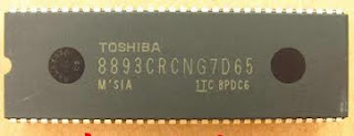
TOSHIBA HAY22- TV KIT [Local TV KIT] – USING 8893 / 0073 / 8891 - HOW TO ENTER SERVICE MODE - DEFAULT SETTINGS

$
0
0


TO ENTER SERVICE MODE
  • Press ‘Menu’
  • Dial ‘6483’ by remote control.
  • Press ‘Mute’ to display a Horizontal Line on screen.
  • Use [1 & 4] digit keys to adjust R-cut.
  • Use [2 & 5] digit keys to adjust G-Cut
  • Use [3 & 6] digit keys to adjust B-Cut
  • To exit service mode, press ‘Mute’ button.

For a second time press of ‘Display’ key, will enter into F1 mode.
  • Press [Ch+] / [Ch -] key to select an item to adjust.
  • Press [Vol+] / [Vol-] key to adjust the data value to selected item.
  • Press ‘Sleep’ button to display Chip’s inner 6 kinds of test signals.
  • To exit, press ‘Display’ key.
SETTINGS

OSD
DESCRIPTIONS
RECOMMENDED DATA VALUE
RC
R-CUT
80
GC
G-CUT
80
BC
B-CUT
80
GD
G-DRIVE
64
BD
B-DRIVE
64
SB
 ======
 =====
U.BLK
U SIGNAL BLACK LEVEL
8
V.BLK
V SIGNAL BLACK LEVEL
8

LOGO
  • Select A/V mode, and dial ‘6568 to get ‘Logo’ display on screen.
  • Press ‘Vol+’ to get ‘Logo-1’.
  • By pressing V + N to shift the cusor, and press [P- / P+] to change the character.
  • To exit, press ‘Display’ key.

OSD
DESCRIPTIONS
DATA
H-PHASE
Horizontal Phase for 50 Hz
18
V.SIZE
Vertical amplitude for 50Hz.
18
V.POS
Vertical Phase for 50Hz
2
V.LIN
Vertical linearty
17
V.SC
Vertical S-Correction
15
HBOW
H bow correction
4
HPARA
H para correction
4
H.BLK.RIGHT
H.Right blanking
0
H.BLK.LEFT
H.Left blanking
0


SONY TRINITRON KV28LS60 - KV32LS60 - SERVICE MODE - SELF DIAGNOSTIC - LED BLINKING CODES

$
0
0

APPLICABLE TO
KV-28LS60B > RM-932 FR SCC-Q83C-A
KV-28LS60E > RM-932 ESP SCC-Q81E-A
KV-28LS60U > RM-932 UK SCC-Q84D-A
KV-32LS60B > RM-932 FR SCC-Q83B-A
KV-32LS60E > RM-932 ESP SCC-Q81D-A
KV-32LS60K > RM-932 OIRT SCC-Q82C-A
KV-32LS60U > RM-932 UK SCC-Q84C-A
SELF DIAGNOSIS
The identification of errors within the AE-6B chassis is triggered in one of two ways :-
1: Busy or
2: Device failure to respond to IIC
   In the event of one of these situations arising the software will first try to release the bus if busy (Failure to do so will report with a continuous flashing LED) and then communicate with each device in turn to establish if a device is faulty. If a device is found to be faulty the relevant
device number will be displayed through the LED (Series of flashes which must be counted) See table 1, non fatal errors are reported using this method. Each time the software detects an error it is stored within the NVM.
TABLE-1
STANDBY LED FLASH TIMING FOR 3 BLINKS
To clear the error count data press ‘80’ on the Remote commander.
ERROR MENU
  • Turn on the main power switch of the TV set.
  • Program Remote Commander for Operation in Service Mode.
  • Press ‘VIDEO’ ‘VIDEO’ > ‘MENU’ on the Remote Commander.
  • Using the Remote Commander, Scroll to the ‘Error Menu’ item using the down arrow key, then press the right arrow key.
  • The following table will be displayed indicating the error count.

TO ENTER SERVICE MODE
Service adjustments to this model can be performed using the supplied remote Commander RM-932.
  1. Press the VCR/TV/DVD button until the TV LED lights.
  2. Press and hold the yellow button for approx. 5 seconds until the TV LED flashes quickly.
  3. Press 99999. All three LED’s should light.  The remote commander is now set to Service Mode.
  • To return the remote commander to normal operation mode repeat steps 1. and 2. then press 00000. All three LED’s should light.
  • The remote commander is now set to normal mode.

SONY TRINITRON KV28LS60 - KV32LS60 - POWER - H-DEFLECTION & OUTPUT - R G B OUTPUT - SCHEMATICS - IMPORTANT PARTS TRACE REPAIR ASSISTANCE DETAILS

$
0
0

MAIN POWER REGULATOR SCHEMATIC
HORIZONTAL DEFLECTION & OUTPUT SCHEMATIC
RG B OUTPUT SCHEMATIC
{Click on Pictures to Magnify}
IMPORTANT COMPONENTS
1-437-430-11 TRANSFORMER, FERRITE (HDT)
1-453-383-21 TRANSFORMER ASSY, FLYBACK (NX4522//Z214)
1-453-340-31 TRANSFORMER ASSY, FLYBACK (NX4522//Z2B4)
1-437-443-11 TRANSFORMER, CONVERTER (PIT)
1-437-483-11 TRANSFORMER, STANDBY
8-749-016-21 IC TCET1103G (Photocoupler)
1-576-232-11 FUSE (H.B.C.) 5A/250V
1-533-725-11 HOLDER, FUSE (F6981)
1-823-853-11 CORD, POWER (KV-28LS60B/28LS60E/32LS60B/KV-32LS60E/32LS60K)
1-776-860-12 POWER CORD, FILTER (UK) (KV-28LS60U/32LS60U)

1-476-702-11 REMOTE COMMANDER (RM-932)
TRACE
A new TV Repair Assistance Tool that combines ease of use and powerful PC software tools to allow you to save valuable time during many TV repairs.
The TRACE interface connects to the PC's serial port. It provides connection to the TV's I2C bus and can be provided with an Infra Red transmitter (optional).

The interface is powered by a standard 9 V PP3 battery for portable use, and can also be powered by an external 9V/25mA DC power supply.
The TRACE software that is supplied with the interface allows you to:
  • Read, restore and compare NVM contents via the I2C bus
  • Acknowledge check of all I2C devices in the TV set
  • Read Error Codes (emulation of the Error Reader tool)
With the optional IR Add-on kit, the following features can be added:
  • Remote Commander emulation
  • User programmable Functional Check through Infrared
  • Fast and documented Test Mode setting of all Sony TV chassis.
Additional features such as Adjustments and Troubleshooting are available in chassis-dependent software modules. Please contact your local Sony Service organization for the latest information.
Note: For workshops already using the existing I2C Link parallel port interface (9-948-320-30), this software can be used as well, replacing the
TV Data Handling software (9-948-340-50), but Error Reader and IR functions can only be accessed with the TRACE interface.
Partnumbers: TRACE Starter Kit (TRACE interface + software): 9-948-320-70
TRACE Software (for users of the I2C Link interface): 9-948-340-80
TRACE IR Add-on (IR interface + Remote Commander software): 9-948-320-80
PC requirements: IBM-compatible PC with operating system Windows95, Windows98, or WindowsNT*.

SONY TRINITRON KV28LS60 - KV32LS60 - HOW TO ENTER SERVICE MODE [FACTORY MODE] - ADJUSTMENTS - DEFAULT DATA VALUES

$
0
0

SERVICE MODE [FACTORY MODE]
Service adjustments to this model can be performed using the supplied remote Commander RM-932.
Programming the Remote Commander for Operation in Service Mode.
  1. Press the VCR/TV/DVD button until the TV LED lights.
  2. Press and hold the yellow button for approx. 5 seconds until the TV LED flashes quickly.
  3. Press 99999. All three LED’s should light.  The remote commander is now set to Service Mode.
  4. To return the remote commander to normal operation mode repeat steps 1. and 2. then press 00000. All three LED’s should light.  The remote commander is now set to normal mode.
SETTING THE TV INTO SERVICE MODE
  • Program the remote commander for operation in Service Mode as described above.
  • Turn on the TV main power switch.
  • Press the video standby button on the remote commander twice.  ‘TT’ will appear in the upper right corner of the screen.  Other status information will also be displayed.
  • Press ‘MENU’ on the remote commander to obtain the following menu on the screen.
  • Move to the corresponding adjustment item using the up or down arrow buttons on the Remote Commander.
  • Press the right arrow button to enter into the required menu item.
  • Press the ‘Menu’ button on the Remote Commander to quit the Service Mode when all adjustments have been completed.
DEFAULT DATA
DEFLECTION SYSTEM ADJUSTMENTS
  1. Program the Remote Commander for operation in Service Mode and enter into the ‘Geometry’ service menu.
  2. Select and adjust each item in order to obtain the optimum image.
TEST MODE - 2
Test Mode 2 is available by programming the Remote Commander for operation in Service Mode then pressing the ‘VIDEO’ button twice, OSD ‘TT’ appears. The functions described below are available by selecting the two numbers. To release the ‘Test mode 2’, press 00, 10, 20  twice or switch the TV set into Stand-by mode. In ‘TT Menu’ mode, it is possible to remove the Menu from the screen by pressing the Speaker Off button once. Pressing the Speaker OFF button a second time will cause the Menu to reappear.  The function is kept even when the menu is not displayed on screen.
CLICK ON PICTURES TO MAGNIFY

PANASONIC SA-AK240GCP – CD STEREO SYSTEM - ERROR CODES - TRANSFORMER & POWER CIRCUITS [SCHEMATICS]

$
0
0

ERROR CODES
The error code is automatically display after entering into self-diagnostic mode.
Self-Diagnosis Function provides information on any problems occurring for the unit and its respective components by displaying the error codes. These error code such as U**, H** and F** are stored in memory and held unless it is cleared.
SELF DIAGNOSIS & SPECIAL MODE SETTING
This unit is equipped with functions for checking and inspecting namely: Self-Diagnostic and Test Mode
SPECIAL MODE TABLE
CLICK ON TABLES TO MAGNIFY
ERROR CODES DISPLAY
CRS1 Error Code display
  • The errors that occurred in CRS1 Mechanism can be recalled and displayed, in the order of the occurrence under self-diagnostic.
  • Only the first 5 errors will be memorized (in backup memory). The subsequence error shall be ignored and not memorize.  For system with EEPROM as memory backup, memory space in EPROM is necessary.
To display all error code memorized
  • In CRS1 Self-Diagnostic mode, press [SINGLE CHANGE] to display subsequence error code.  It shall repeat after reaching error no. 5.
e.g.:
[1____IHMS] =>[SINGLE CHANGE]
[2____ITOP] =>→[SINGLE CHANGE]
[3____HOME] => [SINGLE CHANGE]
[4____LOAD]  =>[SINGLE CHANGE]
[5_____UDD] => [SINGLE CHANGE]
To clear the error code memory
  • In CRS1 Self-Diagnostic mode, long press [SINGLE CHANGE] key (2s or more)
TRANSFORMER CIRCUIT
POWER CIRCUIT

PANASONIC SA-AK240GCP – CD STEREO SYSTEM - DISASSEMBLE PROCEDURE - CD Changer - Necha-chassis & Power PCB

$
0
0


DISASSEMBLY
  • Remove 3 screws at each side and 5 screws at rear panel.
  • Lift up both sides of the top cabinet; push the top cabinet towards the rear to remove the top cabinet.
  • Remove 6 screws.
  • Disconnect cable CN2810 (Fan) at Main P.C.B.
  • Remove rear panel.
Disassembly of CD Changer Unit (CRS1)
  • Remove 1 screw at rear panel.
  • Detach the FFC cables (CN2801 & CN2805).
  • Release the claws on both ends.
  • Lift the CD changer unit upwards to remove it.
Disassembly of Mecha Chassis.
  • Disconnect FFC cables (CN2803, CN2806 and CN2951)
  • Detach connectors (CN2808 & CN2809).
  • Remove Main P.C.B.
  • Disassembly of Transformer P.C.B.
  • Disconnect connectors (CN5950 & CN5951).
  • Remove 3 screws (Mounting screws for transformer to bottom chassis).
  • Push the Transformer P.C.B. sideward to remove it.
Disassembly of Power P.C.B.
  • Remove the 4 screws on Power P.C.B.
  • Detach cable (CN5950) remove the 5 screws on Power P.C.B.
  • Remove Power P.C.B.
  • Note: Insulate the Power P.C.B. with insulation material to avoid short circuit. 
Replacement of the Power Amp IC or Voltage Regulator

  • Remove 2 screws at the Power Amp IC and/or 3 screws to Voltage Regulator.

PANASONIC SA-AK240GCP – CD STEREO SYSTEM - HOW TO DISASSEMBLE - FRONT PANEL - MECHANISM UNIT & TRANSVERSE UNIT

$
0
0


  • Disassembly of Front Panel Unit
  • Disconnect connectors (CN2803, CN2806, CN2951, CN5950 & CN5951).
  • Bent the front panel unit slightly forward as arrow shown.
  • Release 2 claws outwards.
Ensure 2 claws located at the bottom chassis is seated into the 2 slots at bottom of front panel at 2 catches (one on each side) of bottom chassis to be aligned to front panel’s slot.  Assembly is secured upon hearing clicking sound.
Disassembly for Panel P.C.B.
  • Remove the volume knob.
  • Remove Lid.  Note: Do not misplace the spring.
  • Remove 12 screws.
  • Release 2 catches
  • Remove Panel P.C.B.
Disassembly of Lid
  • Lift the spring sidewards. 
  • Remove Lid.  Note: Do not misplace the spring.
Disassembly of Deck mechanism unit.
  • Detach FFC cable (CN971).
  • Disconnect FFC cable (CN1001).
  • Remove the 5 screws.
  • Push the lever upward, and then open the cassette lid ass’y (For DECK1 and DECK2).
  • Tilt the cassette mechanism unit in the direction of arrow (1), and then remove it in the direction of arrow (2).

Disassembly of Deck P.C.B.
  • Remove 2 screws.
  • Desolder wire at deck motor terminals (W1002)
  • Remove Deck P.C.B.
Disassembly of Traverse Unit
  • Ensure all the trays are in the “STOCK” position before proceeding to the disassemble of traverse unit. For procedures to set the trays in “STOCK” position.
  • Press and hold the plunger lever and rotate the gear as arrows shown until it stop.

  • Push the traverse slide plate as arrow shown to release the traverse unit.
Caution: Do not exert strong force on the traverse slide plate.
  • Remove the traverse unit as arrow shown.
  • Turn over the unit and install the traverse unit.

PANASONIC SA-AK240GCP – CD STEREO SYSTEM - HOW TO REPLACE OPTICAL PICK-UP UNIT TO CD MECHANISM

$
0
0

See the procedures to 
Disassembly of Top Cabinet
Disassembly of CD Changer Unit.
Disassembly of Traverse Unit. See previous posts here.
  • Pull out FFC.
  • Widening the catch, push the pin in.
  • Remove 4 pins.

  • Remove the traverse deck.  Note: As floating springs (4 pieces) come off at the same time, be careful not to lose them.
  • Remove 3 screws.
  • Remove the CD Servo P.C.B. and turn it over.  Note: Insert a short pin into FFC of the optical pickup.
  • Rotate the traverse deck (B) to the arrow direction and shift the optical pickup to the furthest backward.

  • Remove the catch of the drive rack, and take out the drive rack.
  • Place the convex part of an optical pickup to the concave part of a traverse base, then take out the optical pickup.


PANASONIC SA-AK240GCP – CD STEREO SYSTEM - HOW TAKE OUT A JAMMED CASSETTE - HOW TO REPLACE CASSETTE LID

$
0
0

TO TAKE OUT A JAMMED CASSETTE 
  • Disassemble the Top of the Cabinet.
  • If a cassette tape cannot be removed from the deck (the tape is caught by the capstan or pinch roller during playback or recording), rotate the flywheel F in the direction of the arrow to remove it.
  • Push the lever upward and open the cassette lid.  Remove the cassette tape.


REPLACEMENT OF CASSETTE LID
  • Lift up the lever upward, open the cassette deck. (For DECK1 and DECK2)
  • Push up the cassette lid (L/R) in the direction of arrow. (For DECK1 and DECK2)


POLAROID FXM-3211C - FXX-321C - HD-LCD TV/DVD COMBO - UNIVERSAL REMOTE CONTROL SET-UP CODES - DISASSEMBLE PROCEDURE - DISPLAY CELL DEFECTS SPECIFICATION

$
0
0

DISPLAY CELL DEFECTS
In some cases, a panel may have defective cells that cannot be controlled. These defective cells can be categorized into two types;
  • Non-lighting or dark cell defect: defect in which the cell is always off
  • Non-extinguishing or bright cell defect: defect in which the cell is always on
The display cell defect specifications define the allowed limits for display cell defects and are used as the criteria in determining whether a panel is replaced.
7 or more pixels across the entire LCD screen Polaroid will repair or replace the TV.

DISASSEMBLY
  • Lay TV flat on workbench. Be careful to protect the front bezel and LCD screen from being scratched. Use protective cloth between workbench and TV front.
  • Remove back covers A, B, and C.
  • Remove DVD Player (A), Cable (B), and Stand Cover (C).
  • Remove six (6) screws from the TV Stand (A) and remove the stand from the TV.
  • Remove all screws from the back cover (Location A).
  • Remove all screws from the rear panel label area (A) and remove back cover.
  • Remove screws from the top and bottom of the two baffles and remove the baffles.
Main Board Removal and Replacement
  • Remove rear cover and baffles as shown in the section.
  • Remove the 4 screws from the top and bottom of the main board cover (Location A), and remove the cover.
  • Disconnect cables on Main Board.

  • Remove all screws from the Main Board (Location A and B) and remove.
UNIVERSAL REMOTE CONTROL SET-UP CODES
GE Universal Remote: 0182 0173 0133
RCA RCR 311W: 1223, 1154, 1155, 1159, 1078
RCA RCR 312W: 11523, 10765, 10865, 11276, 11286, 11314, 11326, 11328, 11341, 11498, 11766, 12002, 12121

PHILIPS MCM277/05/12/98 - MICROSYSTEM - Main Power Schematic - HOW TO DISASSEMBLE

$
0
0

DISASSEMBLE PROCEDURE
  • Press the 2 juts and pull out the Stand as shown.
  • Loosen 5 screws A and 6 screws B to remove the Rear Cabinet.
  • Loosen 3 screws C to remove the SP & ANT Jack Board.
  • Loosen 5 screws D to remove the Power Module.
  • Loosen 2 screws E to remove the Bracket Jack Board as shown.
  • Loosen 3 screws F to remove the Main Board.
DISASSEMBLY OF DISPLAY LENS & VOLUME KNOB
  • Use a flat head screwdriver to give a push in the direction as shown.
  • Place two small screwdrivers in between the front cabinet & knob to give more leverage in pulling out the Volume Knob as shown.
CD MODULE & CD DOOR CARRIER DISASSEMBLY
  • Loosen 5 screws J mounting the Key Board to the Front Cabinet to remove the Key Board.
  • Loosen 4 screws H and 3 screws G to CD Module as shown.
  • Loosen 2 screws I to remove the Servo Motor Mechanism.
  • Loosen 4 screws K to remove the Right CD Door Carrier and 4 screws L to remove the Left CD Door Carrier.
Service Position
After re-assembly, it is very important to ensure all wires are routed properly to ensure that they do not touch/obstruct all moving parts.
MAIN POWER - SCHEMATIC
Click on pictures to Magnify

PHILIPS MCM277/05/12/98 - MICROSYSTEM - MAIN BOARD - MCU BOARD - SCHEMATIC DIAGRAM - Common Faults & Checks

$
0
0

MAIN BOARD SCHEMATIC - TYPE -1
Click on schematics to Magnify
MAIN BOARD SCHEMATIC - TYPE - 2
CD & MCU BOARD SCHEMATIC
MCU PORTION

COMMON FAULTS
PROBLEM
SOLUTION

“NO DISC” is displayed
Insert a disc. Wait until the moisture condensation at the lens has cleared.
Replace or clean the disc, see “Maintenance”.
Use a finalised CD-RW or a correct MP3/WMA -CD format disc

Some files on the USB device are not
displayed
Check if the number of folders exceeds 99 or
the number of titles exceeds 999

Radio reception is poor
If the signal is too weak, adjust the antenna or
connect an external antenna for better
reception.
Increase the distance between the Micro HiFi
System and your TV or VCR

The system does not react when buttons
are pressed
Remove and reconnect the AC power plug and switch on the system again

Sound cannot be heard or is of poor quality
Adjust the volume.  Disconnect the headphones.
Check that the speakers are connected correctly.
Check if the stripped speaker wire is clamped.
Make sure the MP3-CD was recorded within
32~256 kbps bit rate with sampling frequencies at 48 kHz, 44.1 kHz or 32 kHz

The left and right sound outputs are reversed
Check the speaker connections and location

The remote control does not function
properly.
elect the source (CD or TUNER, for example)
before pressing the function button (>|| , |< , >| )
Reduce the distance between the remote
control and the system. Insert the battery with its polarities (+/– signs) aligned as indicated.
Replace the battery.
Point the remote control directly toward
IR sensor on the front of the system.

he timer is not working.
Check the set is switched off.  Set the clock correctly.
Press TIMER to switch on the timer

The Clock/Timer setting is erased
Power has been interrupted or the power cord
has been disconnected. Reset the clock/timer

SAMSUNG HPR-5072 - HOW TO ACCESS SERVICE MODE - WHITE BALANCE ADJUSTMENT - SOFTWARE UPGRADE - VERSION CHECK

$
0
0

SERVICE MODE
Using the Customer Remote
  1. Turn the power off and set to stand-by mode.
  2. Press the remote buttons in this order; MUTE-1-8-2- POWER ON to turn the set on.
  3. The set turns on and enters service mode.
  4. Press the Power button to exit and store data in memory.
If you fail to enter service mode, repeat steps 1 and 2 above.
SERVICE MODE DISPLAY
"T-STRANUS0S-0036" and "T-STRANUS5-0117" are firmware version.  The firmware version is subject to change without notice.
Buttons operations within Service Mode.
  • MENU => Full Menu Display / Move to Parent Menu.
  • Direction keys =>  / Item Selection by Moving the Cursor
  • Direction keys =>  / Data Increase/Decrease for the Selected Item.
  • Source => Cycles through the active input source that are connected to the unit.
WHITE BALANCE ADJUSTMENT

Adjust the basic level of Component,PC and CVBS input signals.
Enter factory Calibration, confirm the ADC data (Component, PC, AV Modes).
ADC default value : Table
B&W LATTICE PATTERN
  • You must perform Calibration in the Lattice pattern before adjusting the White Balance.
  • If you perform Calibration in a pattern other than the Lattice pattern, it causes a malfunction and the operation will not finish.   In this case, press the "EXIT" button on the remote control to terminate the operation.
  1. Enter Service mode.
  2. Apply the NTSC Lattice (No 1) pattern signal to the VIDEO IN port.
  3. Press the Source key to switch to "AV/S-VIDEO" mode.
  4. After confirming that the Lattice pattern appears, select the "Calibration" menu.
  5. Select the "AV Calibration" menu.
  6. In "AV Calibration Off" status, press the "" key to perform Calibration.
  7. When Calibration is complete, it returns to the high-level menu.
  8. Apply the 720p Lattice (No 6) pattern signal to the COMPONENT IN (Y/Pb/Pr) port.
  9. Press the Source key to switch to "COMPONENT" mode.
  10. After confirming that the Lattice pattern appears, select the "Calibration" menu.
  11. Select the "COMP Calibration" menu.
  12. In "COMP Calibration Off" status, press the "" key to perform Calibration.
  13. When Calibration is complete, it returns to the high-level menu.
  14. Apply the 1024x768 Lattice (No 21) pattern signal to the PC IN port.
  15. Press the Source key to switch to "PC" mode.
  16. After confirming that the Lattice pattern appears, select the "Calibration" menu.
  17. Select the "PC Calibration" menu.
  18. In "PC Calibration Off" status, press the "" key to perform Calibration.
  19. When Calibration is complete, it returns to the high-level menu.
  20. All Calibration operations are complete.
HOW TO ADJUST WHITE BALANCE WITH 10 STEPS GRAY PATTERN 
If you don't have Toshiba ABL pattern, you can adjust white balance with 10 steps gray scale pattern.
When you measure Low Light, use 20 IRE portions.
And when you measure High Light, use 70 IRE portion. But if color noise is less in 60 IRE than in 70 IRE, 60 IRE is allowed as a measure point.
SOFTWARE UPGRADE
Downloading boot code
  • Turn off PDP-TV.
  • Connect the RS-232 serial cable to the service jack of PDP-TV.
  • Enter the DOS Mode and move to the directory including "bootdn.bat" and Excute the file.
  • Turn on PDP-TV.
Downloading application code
  1. Turn off PDP-TV.
  2. Connect the RS-232 serial cable to the service jack of PDP-TV.
  3. Enter the DOS Mode and move to the directory including "appdn.bat" and Excute the file.
  4. Power on PDP-TV.
Changing RS-232 serial port and downloaded file
If you want to change serial port, you must edit "bootdn.bat" and "appdn.bat".
  • Don' t turn off during downloading.
  • sdn.exe, download file and Batch file should be in the same directory.
During Downloading,
  • Hyper Terminal should be turned off.
  • Enter a new name.
  • Select a modem port.(com 1 and direct connection.)
  • Set the bit/second to 115200.
  • Set the data bit to 8
  • No parity bit.
  • Set stop bit to 1.
  • No flow control.
  • Save in memory.
  • At this point, the new hyper terminal is ready.
HOW TO CHECK THE FIRMWARE VERSION
  • Select the "Setup" menu in the Menu screen
  • Place the cursor over the "On" of "Function Help", and press the "Info" key on the remote control
  • The version of the program is displayed at the bottom of the Menu screen

Viewing all 2033 articles
Browse latest View live