REPAIR TIPS
Vertical / Horizontal bar, Residual Image, Light spot.
As the part connecting to the external input, check the screen condition by signal.
VIDEO ERROR - VIDEO LAG/STOP. Tuner checking part.
Vertical / Horizontal bar, Residual Image, Light spot.
As the part connecting to the external input, check the screen condition by signal.
VIDEO ERROR - VIDEO LAG/STOP. Tuner checking part.
Checking method:
- Check the signal strength or check whether the screen is normal when the external device is connected.
- After measuring each voltage from power supply, finally replace the MAIN BOARD.
CLICK ON PICTURES TO ZOOM. Click ß at the top of the browser, to come back.
COLOR ERROR
You can view 6 types of patterns using the ADJ KeyChecking item:
- Defective pixel
- Residual image
- MODULE error (ADD-BAR, SCAN BAR.)
POWER ERROR
No Power
Check power input voltage and ST-BY 5V [For ’10 models, thereis no voltage out for st-by purpose. When st-by, only 3.5V is normally on.]
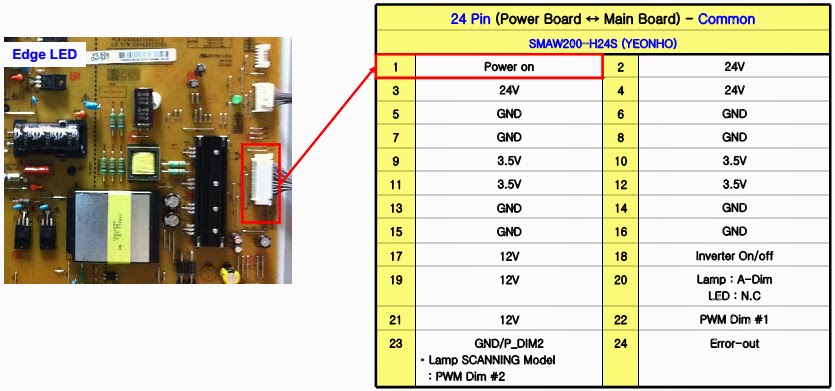
Check the DC 20V/24V, 12V, 3.5V.
Checking method when power is ON
Check “power on” pin is high.
Power error _Off when on, off while viewing. (POWER OFF MODE checking method)
FOR ALL MODELS
Entry method
Press the IN-START button of the remote controller for adjustment
Check the entry into adjustment item 3.
Audio error. No audio/Normal video
Checking method in menu when there is no audio.
Press the MENU button on the remote controller
Select the AUDIO function of the Menu
Select TV Speaker from Off to On.
Voltage and speaker checking method when there is no audio
- Check the contact condition of or24V connector of Main Board
- Measure the 24V input voltage supplied from Power Board. (If there is no input voltage, remove and check the connector)
- Connect the tester RX1 to the speaker terminal and if you hear the Chik Chik sound when you touch the GND and output terminal, the speaker is normal.
Checking order
- Check IR cable condition between IR & Main board.
- Check the STBY 3.3V on the terminal 6.
- When checking the Pre-Amp when the power is in ON condition, it is normal when the Analog Tester needle moves slowly, and defective when it does not move at all.
1. Case
LCD module chang
T-Con board change.
2. Equipment
Service Remote controller
Adjust sequence
- Press the ‘adj’ key
- Select V-COM
- As pushing the right or the left button on the remote controller, And find the V-COM value Which is no or minimized the Flicker. (If there is no flicker at default value, Press the exit key and finish the VCOM adjustment.)
- Push the OK key to store the value. Then the message “Saving OK” is pop.
- Press the exit key to finish V-COM adjustment.


