715G4307 Circuit diagram


Method for entering factory menu:
Press “INPUT”, “2”, “5”, ”8” and “0” in turn to enter factory menu; press “CH+” or “CH-” to select adjustment items and press “VOL+” or “VOL-” to adjust value items, press “MENU” repeatedly to exit. Set AGING MODE of the factory menu to ON,
AGING MODE icon will display on the top left of the screen, now you can press “NR” button to enter the factory menu.
Method for software upgrading:
Prepare the software upgrade program and set the software upgrade tool correctly, press CONNECT then power on, the program will upgrade automatically.
After system prompts upgrade success, press EXIT to exit. When REALTEK appear, it means the upgrade is complete, then restart the unit.
Write HDCP KEY
Turn on the PC and set the software tool correctly, click HDCP then turn on the unit, the program will be written automatically. It needs about 5s and after finish, system will prompt upgrade success.
Note: HDCP button can only be pressed one time for one unit.
The power should be off and 5V-STB disappear for 5s then start writing.
Initialization
Enter factory menu, press “CH+” or “CH-” to select adjustment items and press “VOL+” or “VOL-” to enter the sub menu or adjust value items, adjustment items are shown in table
White balance adjustment
white balance adjustment of HDMI
a. Input VG-848 signal to HDMI port: TIMING854 (800x600/60Hz) and 16-level gray scale signal of PAT920. Use color analyzer CA210 to adjust white balance. BBY model should be adjusted from BBY channel first. The unit must be working for above 30 mins to be in a stabler state for adjustment.
b. Enter factory submenu of TEMP ADJUST, Select NORMAL color temperature (9300k), fixed value of G OFF, adjust R OFF and B OFF, let the color coordinate of the third level be (285±8, 293±12) and the brightness be about 3~5nit. Fixed value of G GAIN, adjust R GAIN and B GAIN, let the color coordinate of the converse third level be (285+/-4, 293+/-6). Adjustment R OFF, B OFF, R GAIN and B GAIN repeatedly until the value of the two levels gray-scale are about (285, 293), then set ALL COLOR to ON.
For BBY model, select COOL color temperature (12000k), fixed value of G OFF, adjust R OFF and B OFF, let the color coordinate of the third level be (272 À5, 278 À5) and the brightness be about 3~5nit. Fixed value of G GAIN, adjust R GAIN and B GAIN, let the color coordinate of the converse third level be (272+/-2, 278+/-2). Adjustment R OFF, B OFF, R GAIN and B GAIN repeatedly until the value of the two levels gray-scale are about (272, 278), then set ALL COLOR to ON.
VGA/YPBPR/AV white balance check and correction
a. Input VG-848 signal of VGA to VGA terminal: TIMING854(800x600/60Hz) (PATTERN:CROSS) and auto adjust to full screen, then input PAT948 black/white signal, enter factory menu ADC ADJ, select AUTO COLOR and the system will correct automatically, after finish, it will return to AUTO COLOR menu. Please check the picture and data, if they are abnormal, then the correction is failure and needs to correct again. (abnormal symptom: certain of the data are greatly different from other data or exceed or near 1000).
Input PAT920(16 gray levels), check if the white balance is normal, if not, enter TEMP ADJUST menu and set ALL COLOR to OFF and fine adjust according the method of 3.5.1b)
b. YPBPR check and correction
SD correction: input VG-848 signal of YPBPR to YPBPR terminal and input TIMING968 (480i) PAT968 color bar (see fig2), (color from left to right are white- yellow- cyan- green- purplered- blue- black), enter ADC ADJ submenu, select AUTO COLOR the system will correct automatically, after finish, it will return to AUTO COLOR menu. Please check the picture and data, if they are abnormal, then the correction is failure and needs to correct again.
HD correction: input VG-848 signal of YPBPR to YPBPR terminal and input TIMING976 (720P/60Hz) PAT968 color bar (color from left to right are white- yellow- cyan- green- purple- redblue- black), enter ADC ADJ submenu, select AUTO COLOR the system will correct automatically, after finish, it will return to AUTO COLOR menu. Please check the picture and data, if they are abnormal, then the correction is failure and needs to correct again.
Input PAT920(16 gray levels), check if the white balance is normal, if not, enter TEMP ADJUST menu and set ALL COLOR to OFF and fine adjust according the method of 3.5.1b)
c. Input AV signal (PM5518, 8 gray levels, PAL for China and NTSC for America) to VIDEO terminal, check if the white balance is normal, if not, set ALL COLOR to OFF and fine adjust according the method of 3.5.1b)
Software instruction
Table3 software instruction
No. | Code No. | Type | Function | Written | Method | Remarks |
NS3 | 5272540001 | PM25VF040 | Main CPU | Yes | ||
NB1 | 5272402002 | 24C02N-10SI27 | VGA EDID | Ye |
Written with instrument like ALL11
Item Setting Item Setting Item Setting
PICTURE MODE | NAUTRAL |
SOUND SYSTEM | DK (China), |
SOUND MODE | NEWS |
NR | WEAK |
ZOOM | FULL |
LANGUAGE | English |
| |
TRANSPARENCY | 2 | VGA/HDMI COLOR | STANDARD |
OSD TIME | 10 | ANTENNA | CATV |
4.6 Check AV channel
Check if AV OUT is normal?
Enter factory menu and select RESET, then the unit will be preset before ex-factory. The process must be executed after the whole adjustment in factory.
Setting as follow without specified requirement.
Power supply (SMPS) schematic
Audio amplifier schematic
Applicable to - KDL-39R475A - KDL 42R474A - KDL 42R475A - KDL 46R475A (RB1TK Chassis)
KDL-39R475A RM-YD093 BRAZIL
KDL-42R474A RM-YD093 BRAZIL
KDL-42R475A RM-YD093 BRAZIL
KDL-46R475A RM-YD093 BRAZIL
REPLACING THE MAIN BOARD
The Main Board used in these models is available for repair.
Steps for repair
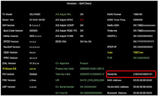
How to access the service mode.
8. Access Service Mode by pressing the following buttons within 1 second of each other:
9. Press the DOWN until Panel Selection is selected.
10. Press LEFT or RIGHT to select the correct Panel Code for the TV model.
(Use the table below for reference). CAUTION: Select ONLY the correct Panel Code.
11. Locate the Serial Number for the TV on the side of the Rear Cover.
12. Press DOWN until SERIAL NUMBER EDIT is selected.
13. Press RIGHT to be able to select the first digit.
14. Press UP or DOWN to select numbers and then RIGHT to move to the next digit until Serial Number is complete.
When the complete serial number displays, press (+)
On the confirmation screen, press LEFT to select YES and then (+)
17. Press until MODEL NAME EDIT is selected.
18. Press RIGHT to be able to select the first character.
19. Press UP or DN to select characters and then RIGHT to move to the next space until Model Name is complete. NOTE: Make sure to include dash in Model Name.
CAUTION: The Model Name can only be selected once. Be sure to verify the information is correct before saving the changes.
20. When the complete Model Name displays, press (+) .
21. On the confirmation screen, press LEFT to select YES and then (+)
22. Press the POWER to EXIT the SERVICE MODE.
LG M3201C-BAFE.A**LLC, M3701C M3701C-BAFE.A**LLC, M4201C M4201C-BAFE.A**LLC
There are some special components used in LCD monitor that are important for safety. These parts are marked on the schematic diagram and the replacement parts list. It is essential that these critical parts should be replaced with the manufacturer’s specified parts.
If the surface of panel becomes dirty, please wipe it off with a soft material. (Cleaning with a dirty or rough cloth may damage the panel.)
Do not apply AC power to this instrument and/or any of its electrical assemblies unless all solid-state device heat sinks are correctly installed.
Minimize bodily motions when handling unpackaged replacement ES devices. (Otherwise harmless motion such as the brushing together of your clothes fabric or the lifting of your foot from a carpeted floor can generate static electricity sufficient to damage an ES device.)
Block diagram
Description of block diagram
AV input selection circuit
1) AV(Video) INPUT SELECT : This section is composed of Video switching IC (CXA2040AQ_IC513) and peripheral devices.
Video switching IC(CXA2040AQ_U201) selects CVBS video or S-video and the signal is sent to Scaler IC(IC101).
2) AV Sync Detection : This section is composed of Sync Separator IC(LA7217M_IC509) and peripheral devices.
Av input selection block sends selected signal to Sync detection block then sync detection block identifies if AV signal is present or not. And this block sends this information to Scaler(Micom).
2. Component INPUT
Component input signal was connected from input jack to scaler directly.
3. RGB INPUT OUTPUT CIRCUIT
1) D-SUB RGB INPUT OUTPUT : This section is composed of RGB Input Output Jack(P503), Schmitt trigger inverter IC(IC507), OP-AMPs(IC510, IC511, IC512) and peripheral devices.
RGB input signal path was connected from input jack to Scaler directly. But scaler receives RGB Sync signal via schmitt trigger inverter IC.
RGB output signal was made by OP-Amp ICs. And this sends output signal to RGB output jack.
4. HDMI INPUT CIRCUIT
This section is composed of TMDS receiver IC(ANX9021_IC508), ESD protection diode(CM2021_D526, D527) and peripheral devices.
TMDS receiver IC receives TMDS signal via ESD protection diode. And it convert HDMI signal to digital RGB signal. And it sends to scaler.
5. RS-232C INPUT OUTPUT CIRCUIT
This section is composed of RS-232C IC(ICL3232C_IC503), and peripheral devices.
Computer and scalar(micom) was connected by RS-232C IC.
7. AUDIO DECODER
This section is composed of MSP4440K(IC804), NTP2000(IC805) and peripheral devices.
MSP4440K is processing audio signal(AV, Component, PC Audio and IIS).
Digital audio processor IC receives IIS signal from MSP4440K, and converts IIS to PWM signal.
This IC's output signal is sent to Audio Amplifier IC(TAS5122_IC802).
8. AUDIO AMPLIFIER
This section is composed of TAS5122(IC802) and peripheral devices.
Audio Amplifier's function is amplification of sound signal received from Audio Decoder.
Input Audio signal is amplified according to the DC Volume control curve.
Adjustment
All adjustment are thoroughly checked and corrected when the monitor leaves the factory, but sometimes several minor adjustments may be required.
Adjustment should be following procedure and after warming up for a minimum of 30 minutes.
Alignment appliances and tools.
- IBM compatible PC
- Programmable Signal Generator. (eg. VG-819 made by Astrodesign Co.)
- Oscilloscope.
- White Balance Meter. (CA-110)
DDC Data Write Procedure-Analog
1) Use this procedure only when there is some problem on Analog EDID data.
2) Run alignment program for M3201C on the IBM compatible PC.
3) Select EEPROM →Analog EDID write command and Enter.
4) This will write the Analog EDID data to EEPROM.
2. DDC Data Write Procedure-Digital
1) Use this procedure only when there is some problem on Digital EDID data.
2) Run alignment program for M3201C on the IBM compatible PC.
3) Select EEPROM →Digital EDID write command and Enter.
4) This will write the Digital EDID data to EEPROM.
Cable Connection
Windows EDID V1.0 User Manual
Service OSD
The OSD is displayed when 'ADJ Key is pressed on ADJUST REMOCON in Service Menu.
Description of operation
- LW61A : Model chassis
- Cortez Version : Software Version
- Panel Used : Use time the Panel
- Area Option
- OPTION 1
- OPTION 2 Not Use
- OPTION 3
- OPTION 4
- System Control 3 : Debug Print Set up
- Power-off History : History Memory of Abnormal
- Fan Control : Nothing
The OSD is displayed when 'OK' Key is pressed on Tool Option 1 in Service Menu.
Tool Option 1
- MODULE : Inch, make factory Module change
- Cortez Version : Fix SW (Not change)
The OSD is displayed when 'OK' Key is pressed on Tool Option 2 in Service Menu.
Tool Option 2
- Tuner Num. : Fix No Tuner (Not Adjust)
- EYE : Fix Intelligent Eye Not Action (Not Adjust)
- INDEX : Nothing
- RGB ONLY : Select the RGB Only Model
- Full : Set the ARC Full
- HDMI Type : Fix HDMI : 1-HDMI (Not Adjust)
The OSD is displayed when 'OK' Key is pressed on System Control 1 in Service Menu.
System Control 1
- SpritZoom / Save sprilt Zoom : Nothing
- 2 Hour Off opt. : If no key input is made for 2 hours, Sets the Power off
- OSD Rotate : Nothing
- Favorite Key / Exit Key / Navigation Key : Remot conntroller Key (Not adjust)
The OSD is displayed when 'OK' Key is pressed on System Control 2 in Service Menu.
System Control 2
- System : Sets the Color system mode
- OverScan : Sets the Video Signal OverScan
- RS-232 Host : Nothing
- Baud Rate : Sets the RS-232 communication speed
- RS-232 Select : Select the RS-232 communication
- AGC-L : Nothing
- Audio Delay : Sets the Audio Delay(ms)
The OSD is displayed when 'OK' Key is pressed on BlkLine Detector in Service Menu.
BlkLine Detector
- BlkLine Min : Sets the BlkLine Min
- BlkLine Max : Sets the BlkLine Max
- Full Time : Sets the Full time
- Original Time : Sets the Original time
The OSD is displayed when 'OK' Key is pressed on Panel Control in Service Menu.
Panel Control
- AV / PC : Nothing
- ISM : Nothing
- Gamma : Nothing
- Pwr.Save : Nothing
- Bright : Nothing
- Pnl.Lock : Nothing
- OrbitPixel : Sets the Pixel
- Orbit Step : Sets the Step
- Orbit Time : Sets the Time
- Inv.Time : Sets the inversion time
- GUC : Nothing
- AMSE : Nothing
- Module Download : Nothing
- Reset Panel Used Time : Reset the Panel Use Time
Hotel option
Hotel Option
- Station Menu Display : Nothing
- Program Change : Nothing
- Input Source Change : Enables (Yes)/Disables (No) input source change.
- Fixed Volume : Sets Yes (Fixed)/No (Variable) about whether the sound volume will be fixed to the current value or not.
- Max Volume : Sets the maximum volume within the range of 0 ~ 100 when volume control is allowed.
- OSD Display : Nothing
- Remote Control Operation : Activates (Yes)/Deactivates (No) remote control operation.
- Local Key Operation : Activates (Yes)/Deactivates (No) local key operation.
- Power On Operation : Sets Yes (Operation)/No (No operation) about whether the channel and the volume level that will be displayed when the power is turned on.
- Set ID Lock : Sets the Set ID function
- Set ID : Attach ID
- Auto Off Operation : Sets whether the automatic turn-off function will be activated or not with On (Activated) or Off (Deactivated) option, which turns off the TV if no key input is made for 2 hours, using Auto Off operation and On Time on the Time menu.
- Hotel Mode Operation : Sets whether all Hotel functions will be enabled
(Yes) or disabled (No).
Auto color balance and white balance
Auto Color Balance (Hex) : Adjust Color Balance
White Balance:Adjust White Balance
Models:
LC-26/32D44EE-BK/GY → Continental
LC-26/32D44ES-BK/GY → Sweden Market
LC-26/32D44EK-BK/GY → United Kingdom
LC-26/32D44
LC-26 and LC 32D44 Models
ASV & Black TFT LCD.
• HD Ready Panel (1366 x 768) WXGA with 4ms response.
• Wide vision angle (H/V 176º).
• High brightness and contrast (1.500:1).
• Interlaced and progressive mode compatible (I/P).
• Built-in DVB-T Tuner.
• Multistandard Video and audio:
- Multistandard Video & audio .
- Video: PAL/SECAM & NTSC (AV only).
- TV: B/G, I, D/K, L & L’.
- Sound: NICAM & A2 (IGR).
• OSD multilanguage.
• 2 HDMI 1.2 inputs (Video Digital, Audio Digital & Analog).
• Analog mode PC input.
• Components Input ( 3RCA to 15pin D-sub adapter).
• RGB at EXT1/EXT2 Terminal.
• RS-232C.
• AV-Link at EXT2.
• Does not support CEC at HDMI.
• Active Backlight (dynamic contrast 10.000:1)
• Sleep Timer.
• Does not support “RC Path Through” by Pin Nº 9 of Service Connector.
Dual-Input HDMI 1.2, HDCP 1.1 and DVI 1.0 compliant receiver.
2- Integrated TMDSR core.
3- Digital video interface supports video processors:
• 24-bit RGB/YCbCr 4:4:4
• 16/20/24-bit YCbCr 4:2:2
• 8/10/12-bit YCbCr 4:2:2 (ITU BT.656)
• 12-bit DMO (Digital Multimedia Output) RGB/YCbCr 4:4:4 (clocked with rising & falling edges)
• Color Space Conversion for both RGB-to-YCbCr and YCbCr-to-RGB (both 601 and 709)
• Auto video mode configuration simplifies system firmware design.
4- Digital audio interface supports high-end audio systems:
• One programmable I2S output for connection to low-cost DACs at 32-192kHz.
• S/PDIF output supports PCM, Dolby Digital, DTS digital audio transmission (32-192 kHz Fs) using IEC60958 and IEC61937.
• Auto audio error detection with programmable soft mute.
5- Integrated HDCP decryption engine for receiving protected audio and video content.
6- HDCP Built in Self Test (BIST) lowers cost to test HDCP operation.
7- Pre-programmed HDCP keys provide highest level of key security, simplifies manufacturing.
IC1922 & IC1902: NVM OF HDMI (E-EDID)
Part Number : 24LC2BIN SHARP Code: VHI24LC2BIN-1Y
This IC is a 2-wire (I2C bus type) serial EEPROM this is electrically programmable. This EEPROM chip stores the data structure used to carry configuration information for optimal use of a display (EDID data).
IC4001: DIGITAL PROCESSOR MPEG 1/2 DECODER (Audio/Video)
Part Number : STI5105ALC SHARP Code: RH-IXC243WJZZQ
The STi5105ALC sets a new standard for set-top box decoder ICs, delivering outstanding performance, features and innovations to dramatically reduce cost compared with previous generations. The Sti5105 features an even faster ST20CPU with direct map, single cycle caches to boost performance.
Graphics and display capabilities have been enhanced with the provision of a blitter engine for formatting and fi nal display composition. Color formats (CLUT8 and true color ARGB16) and display planes (background, still picture, video and OSD graphics) are provided. Overall system performance benefits from the integration of SDRAM (DDR or SDR) external memory, that provides a unified memory system with high bandwidth and low latency CPU access over a 16-bit interface.
System cost reduction is further promoted by the integration of additional peripheral and system services functions, such as VCXO, an enhancer reset controller DVB-CI support, smart card power control and improved low power and standby functionality.
1-An enhanced ST20 32-bit VL-RISC CPU with a 200MHz clock, 4Kbytes of instruction cache, 4Kbytes of data cache and 2Kbytes of embedded SRAM.
2- A 16-bit, 166MHz Shared Memory Interface, with support for 64- and 128-bit configurations.
3- A programmable External Memory Interface supporting 4 separately configurable banks of SRAM, Flash and DRAM.
4- An MPEG-2 (MP@ML) decoder, including trick modes such as smooth fast-forward and rewind.
5- A Graphics/Display unit with 4 display planes, alpha blending, ant aliasing and ant flutter filters, sub picture decoder, and blitter display compositor with separate OSD (On-Screen Display) controls for TV and VCR outputs.
6- PAL/NTSC/SECAM encoder.
7- CGMS, Teletext, WSS, VPS encoder.
8- MPEG-1 layer I/II audio subsystem with embedded DSP for all popular audio formats.
9- A full range of on-chip peripherals, including 2 UARTs, 3 parallel I/O banks, 1 smartcard interface, four PWM channels, 1 IR transmitter/receiver etc.
IC4252: NVM 64Kb-E2PROM FOR DIGITAL PROCESSOR (IC4001).
Part Number : BR24S64FVM-WTR SHARP Code: VHIBR24S64M-1Y
The BR24S64FVM is a 2-wire (I2C bus type) serial EEPROM that is electrically programmable. This IC stores all data related to the Digital Module (channels, user settings etc)
IC3001: Main CPU / VIDEO PROCESSOR.
Part Number: VCT7993P-FA-A1-H000 SHARP Code: RH-IXC354WJZZQ
The VCT 77VWP (VCT-Pro) family is dedicated to high-quality FPD and double-scan TV sets. The memory and program ROM are integrated in the IC. Modular design and deep submicron technology allow the integration of audio, video, Teletext, OSD, and controller-related functionalities.
They cover the whole range of fl at-panel display TVs. Each member of the IC family contains the entire audio, video, up-conversion processing for 4:3 and 16:9 50/60 Hz progressive or 100/120 Hz interlaced stereo TV sets plus the control/data interface for flat-panel displays. The integrated microcontroller supports a powerful OSD and graphics generator with integrated Teletext acquisition.
The VCT 77vwP family provides a front-end video-processing unit with 4 CVBS-Y/C or component inputs for HDTV, EDTV and SDTV. A VBI slicer, support of 2000 pages of Teletext, and a 3-D comb fi lter for PAL and NTSC (in certain versions) are also available. The front-end unit further allows processing an SD and an HD source in parallel, thus enabling PiP and PaP functionality. Motion-adaptive de-interlacing, temporal noise reduction, and fi lm mode detection are based on a unified memory technology. Post-scaling in the display-processing block ensures the desired output format.
Display processing is supported by an 8-bit 8051-compatible controller. By means of powerful alpha blending, the graphics mixer composes the output image from following image layers: the video layer, the OSD layer and the pixel graphics layer. The audio part consists of a multi-standard sound IF demodulator and a base-band processor supporting all desired sound features in this range.
The VCT-Pro front-end video processing unit offers 16 analog video inputs (CVBS/Y/C, RGB/Y Cr Cb) as well as digital interfaces for SDTV and HDTV. Latest 3D+ comb fi lter generation provides highest performance for PAL/NTSC signals.
A VBI slicer, supporting up to 2000 pages of Teletext completes the analog video front end. 3D-motion-adaptive de-interlacing, temporal noise reduction and fi lm mode detection are based on a unified memory technology.
This IC includes the main features show below:
1- Stereo Decoder Audio Processing.
2- Video Front-end 3D Comb fi lter, PC Connectivity.
3- Motion Adaptive Deinterlacer.
4- Scaling, Display Processing and FPD Control.
5- Unified Memory for Audio, Video and Teletext.
6- OSD and Teletext processor.
7- Main CPU(TV controller)
IC3051: NVM 64Kb-E2PROM FOR ANALOG PROCESSOR (IC3001).
Part Number: BR24S64FVM-WTR SHARP Code: VHIBR24S64M-1Y
The BR24S64FVM is a 2-wire (I2C bus type) serial EEPROM that is electrically programmable. This IC stores all data related to the Analog Module (Channels, User settings, etc.)
IC2302: SUB-CPU AND PORT EXPANSOR.
Part Number: TMP86FS49AUG-6NU2 SHARP Code: RH-IXC009WJZZQ
This IC functions as ports Expansor of the main microcontroller (e.g leds, remote control, key, Power Supply supervisor, Audio mutes, LCD controller signals, temperature sensor, lamp error, etc..).
This microcontroller integrates 60KB of Flash memory, 2KB of RAM. It’s including 56 I/O pins (13 high current) with 2 UARTS, 1 I2C serial link, 16 channels of 10 bits A/D converters, 2 timers 16 bits.
IC1301: DIGITAL AUDIO POWER AMPLIFIER
Part Number: YDA147-SZE2 SHARP Code: VHIYDA147SZ-1Y
This IC is a Stereo 20W (10W+10W) digital audio power amplifier. The IC is class D amplifi er equipped with the function for the dynamic self-adjustment of the output volume in proportion to the amplitude of the input signal. The company calls the function of automatic adjustment of the installed
output volume “DRC (dynamic range compression)”.
The modulation method adopted PWM. An external LC fi lter is unnecessary. It only has to supply the output signal directly to the speaker. It has the
output control function to prevent an excessive input to the speaker. The maximum output electric power can be set to an arbitrary size by external
resistance. Besides this, the protection function to overheating and the over current was installed.
The switching operation of power MOS-FET is installed and the technology that carefully controls the slewing rate is installed. Moreover, the automatic offset circuit that suppresses the pop noise when the power supply start is built into.
IC8103: LCD CONTROLLER
Part Number: T3Z18AFG-0003 SHARP Code: VHIT3Z18AFG-1Q
This IC is a custom Gate Array of Toshiba. The alias of this IC is EAGLE2 and is marked as SHARP. This IC is generating all the necessary timing signals for controlling the panel and the RSDS interface for data..
IC8101: NVM 256Kb -E2PROM FOR LCD CONTROLLER (IC8103)
Part Number: M24256-BWMN6TP SHARP Code: VHIM24256B +-1L
The BR24256B is a 2-wire (I2C bus type) serial EEPROM that is electrically programmable. This IC stores all data related to the LCD Controller (Gamma, timings, etc…)
IC203: I2C BUS SELECTOR
Part Number: SN74LV4053APWR SHARP Code: VHILV4053AT-1Y
The SN74LV4053APWR is a high-speed CMOS analogue multiplexer/demultiplexer backed by silicon gate CMOS technology. The multiplexer function includes the selection and mixing of analogue and digital signals. The chip includes two independent 3 channels selectors. A digital signal through the control terminal turns on the switch of a corresponding channel. This IC is selecting if the Tuner is controlled from VCT-Pro (ATV mode) or from OFDM decoder (DTV mode).
IC1201: NVM OF PC INPUT (EDID)
Part Number: BRC21F SHARP Code:VHIBR24C21F-1Y
This IC is a 2-wire (I2C bus type) serial EEPROM this is electrically programmable. This EEPROM chip stores the data structure used to carry configuration information for optimal use of a display (EDID data).
IC1501: RS-232 TRANSCEPTOR
Part Number: ISL83220 SHARP Code: VHIISL83220-1Y
This ISL83220 is a 3.0V to 5.5V powered RS-232 transceiver (emitter/receiver), +/-15kV ESD protected, with a maximum data rate of 250 kbps.
HOW to update the software
VCTPro SOFTWARE UPDATE
There are 4 methods to update software in the VCTpro:
• RS-232C HyperTerminal Method
• RS-232C Tera Term Method
NOTE: (RS-232C method is allowed when the TV is working properly and the action should be only software upgrade)
• I2C Method
• PCMCIA card method (new)
DIGITAL SOFTWARE UPDATE
There are 2 methods to update the Digital Board Software on Flash Memory (IC4203) throught the Digital Processor (IC4001):
• PCMCIA CARD (Compact Flash Memory) Method
NOTE: The PCMCIA method is only compatible with those PCs running XP Windows Version.
• Jig RS-232 WinUpload Method (from PC through RS-232C COM port)
Press the “POWER” key on the set of running TV set to force off the power.
While holding down the “VOL (-)” and “INPUT” keys on the set at once, plug in the AC power cord to turn on the power.
The letter “K”, appears on the screen.
Next, hold down the “VOL (-)” and “P (-)” keys on the set at once. Multiple lines of character string appearing on the screen indicate that the set is now in the adjustment Process mode. If you fail to enter the adjustment mode (the display is the same as normal start-up), retry the procedure. (Another procedure)
To exit of Service Mode, after the adjustment is done, unplug the AC power cord to force off the power. (When the power is turned off with the remote controller, once unplug the AC power cord and plug it in again. In this case, wait 10 seconds before plugging.
Main Key operation in adjustment process
Main ICs
IC207: COFDM DECODER (Coded Orthogonal Frequency Division Multiplexing)
Part Number : STV0362 SHARP Code: RH-IXB964WJZZQ
The STv0362 is a single-chip demodulator using COFDM and is intended for digital terrestrial receivers using compressed video, sound and data services. It converts IF or base band differential signals to MPEG-2 transport stream format by processing OFDM carriers. The STv0362 is fully compliant with the DVB-T specification (ETS 300 744) and Nor Dig Unifi ed specifi cation.
IC1951: HDMI RECEIVER (High Definition Multimedia Interface)
Part number : Sii9025 SHARP Code : VHISII9025+-1Q
The Sii9025 is a compliant with the latest HDMI 1.2 (High Definition Multimedia Interface) specification. Backward compatibility with DVI 1.0 allows
HDMI systems to connect to existing DVI 1.0 hosts. The SiI9025 is capable of receiving and outputting two channel digital audio at up to 192 kHz an excellent solution for Digital TVs. An S/PDIF port supports up to 192 kHz audio. The SiI9025 also comes pre-programmed with HDCP keys,
greatly simplifying the manufacturing process, while providing the highest level of HDCP key security.
This IC includes the main features shown below
The colors of K letter that shown on the screen when TV is at Inspection Mode are as follows:
Red | Picture adjustment: without making adjustments. (SRC or after delete NVM ) |
Tuner level adjustment
WB (White Balance adjustment from PC)
W/B ADJUSTMENT FROM PC
1- Get ready the PC with COM port (RS-232C) running on Windows 95/98/ME/2000/XP operating system, as well as the RS-232C cross cable.
2- Start the unit with the RS-232C cable connected.
3- Start the terminal software. (The freeware readily available on the Internet will do.)
4- Make the following settings:
Baud rate | 9.600 bps None |
5- If the settings are correct, the terminal software indicates “ERR” against pressing of the “ENTER” key.
6- After the setting are done correctly, it is possible to make an adjustment by typing in the command shown in the table below and pressing the “ENTER” key on the keyboard.
7- Command entry is successful if the terminal software indicates “OK” when the “ENTER” is pressed. If “ERR” is shown, retry to enter the command.
8- Send the process mode switching command to switch from the RS232C operation mode to the process mode:
KRSW0001: “ERR” is returned.
KKT10037 : When “OK” is returned, the process mode becomes active. When “ERR”, start over from KRSW0001.
9- Send each adjustment command.
List of Commands
HOTEL MODE
How to Enter in the Public Mode (Hotel Mode)
There are three following ways to display the Public Mode setting screen.
1- On the process adjustment mode screen (2/33), set the “HOTEL MODE” Flag to ON.
Turn off the power, and turn it on again, pressing the CH▲ and Vol▲ keys of the main unit at the same time.
2- Enter the Pass Word, and start the unit.
a) Turn on the power, pressing the INPUT and Vol▲ keys of the main unit at the same time.
b) Display the Pass Word input screen.
c) Check the Pass Word by inputting three digits. If the Pass Word is ( 0 2 7) , it shifts to the Public Mode setting screen. In another case, the screen is erased, and it operates in the ordinary mode.
3- By special R/C code: RC table LCD, SYS CORD: 0x78, RC DATA: (HEX) 0xC7, (DEC)199.
After one of sequence before mentioned, the TV will turn on showing the Public Mode set
Exiting the Public Mode screen
There are two following ways to exit the Public Mode setting screen.
1- Turn off the power.
2- Select “Execute” in the Public mode to execute it.
Public mode settings
POWER ON FIXED [VARIABLE FIXED]
When it is set to “FIXED” the TV is impossible to be switch off by Main Switch or Remote Control.
2. MAXIMUM VOLUME [0 60]
Is possible to set the maximum volume at limited level.
3. VOLUME FIXED [VARIABLE FIXED]
Is possible to fi x the sound volume at limited level.
When “FIXED” is selected the sound volume before limited is fi xed.
4.VOLUME FIXED LEVEL [0 60]
If “FIXED” has been selected, is possible to set a fi xed volume at the level that is chosen.
5. RC BUTTON [RESPOND NO RESPOND]
If “NO RESPOND” is selected, the remote control keys are inoperative.
6. PANEL BUTTON [RESPOND NO RESPOND]
If “NO RESPOND” has been selected, the set´s keys remain deactivated (Except POWER key).
7. MENU BUTTON [RESPOND NO RESPOND]
If “NO RESPOND” has been selected, “MENU” keys on the remote control, is inoperative.
8. ON SCREEN DISPLAY [YES NO]
If “NO” has been selected, the On Screen Display does not appear.
9. INPUT MODE START [ NORMALTV (X)DTVINPUT1 INPUT2INPUT3 INPUT4 INPUT5 INPUT6 INPUT7]
When any other item than “NORMAL” has been selected, the sets will start in a selected input mode at the next power-on.
10. INPUT MODE FIXED [VARIABLE FIXED]
If “FIXED” has been selected, any channels and input modes other than those selected at the start mode cannot be picked up.
11. RESET
Cancel all Public Mode settings. (It returns to the factory settings)
12. EXECUTE
Select this item, and press cursor RIGHT/LEFT keys on the remote control ir VOL(+) or (--) keys on the LCD TV for confirmation the function settings.
26 Inch Power-Inverter schematic
32 Inch Power supply schematic and 32 Inch Inverter schematic
No. G03-NMF92-F, Rev: 1.0. Release date: February 6, 2012
Layout diagram
Hardware installation
Rear I/O Back Panel Connectors
(1) High-Definition Multimedia Interface: HDMI1
This point-to-point interface is for audio and video signals designed as a single-cable solution for home theater and consumer electronics equipment.
(2) Serial port Connector: COM1
COM1 offers two 9-pin serial port connectors.
(3) Digital Visual Interface: DVI
This interface standard designed to maximize the visual quality of digital display devices such as flat panel LCD computer displays and digital projectors.
(4) D-Sub 15-pin Connector: VGA
VGA connector is the 15-pin D-subminiature female connector; it is for the display devices, such as the CRT monitor, LCD monitor and so on.
(5) USB Port Connectors: USB ports from USB1/UL1/ UL2
The connectors are 4-pin connector that connects USB devices to the system board.
(6) LAN Port connectors: RJ45 LAN ports from UL1/UL2
The connector is standard RJ45 connector for Network. It supports
10/100/1000Mbps data transfer rate.
(7) Audio Line-In, Lin-Out connector: AUDIO1
These Connectors are 3 Phone-Jack for LINE-OUT, LINE-IN, MIC audio connections.
Line-in: (BLUE) | Audio input to sound chip |
Motherboard Internal Connectors
(1) Power Connector (24-pin block): ATXPWR
ATX Power Supply connector: This is a new defined 24-pins connector that usually comes with ATX case. The ATX Power Supply allows using soft power on momentary switch that connect from the front panel switch to 2-pins Power
On jumper pole on the motherboard. When the power switch on the back of the ATX power supply turned on, the full power will not come into the system board until the front panel switch is momentarily pressed. Press this switch again will turn off the power to the system board.
** recommend that you use an ATX 12V Specification 2.0-compliant power supply unit (PSU) with a minimum of 350W power rating. This type has 24-pin and 4-pin power plugs.
** If you intend to use a PSU with 20-pin and 4-pin power plugs, make sure that the 20-pin power plug can provide at least 15A on +12V and the power supply unit has a minimum power rating of 350W. The system may become unstable or may not boot up if the power is inadequate.
** If you are using a 20-pin power plug, please refer to Figure1 for power supply connection. Power plug form power supply and power connectors from motherboard both adopt key design to avoid mistake installation. You can insert
the power plug into the connector with ease only in the right direction. If the direction is wrong it is hard to fit in and if you make the connection by force if is possible.
ATX 12V Power Connector (8-pin block) : ATX12V
This is a new defined 8-pin connector that usually comes with ATX Power Supply. The ATX Power Supply which fully supports AMD AM3 processor must including this connector for support extra 12V voltage to maintain system power
consumption. Without this connector might cause system unstable because the power supply can not provide sufficient current for system.
The BIOS is a program located on a Flash Memory on the motherboard. This program is a bridge between motherboard and operating system. When you start the computer, the BIOS program will gain control. The BIOS first operates an auto-diagnostic test called POST (power on self test) for all the necessary hardware, it detects the entire hardware device and configures the parameters of the hardware synchronization.
Only when these tasks are completed done it gives up control of the computer to operating system (OS). Since the BIOS is the only channel for hardware and software to communicate, it is the key factor for system stability, and in ensuring that your system performance as its best.
Entering Setup
Power on the computer and by pressing <Del> immediately allows you to enter Setup.
If the message disappears before your respond and you still wish to enter Setup, restart the system to try again by turning it OFF then ON or pressing the “RESET” button on the system case. You may also restart by simultaneously pressing <Ctrl>,<Alt> and <Delete> keys. If you do not press the keys at the correct time and the system does not boot, an error message will be displayed and you will again be asked to Press < Del > to enter Setup
BIOS Menu Screen
The following diagram show a general BIOS menu screen:
Function Key
In the above BIOS Setup main menu of, you can see several options. We will explain these options step by step in the following pages of this chapter, but let us first see a short description of the function keys you may use here:
z Press ←→ (left, right) to select screen;
z Press ↑↓ (up, down) to choose, in the main menu, the option you want to confirm or to modify.
z Press <Enter> to select.
z Press <+>/<–> keys when you want to modify the BIOS parameters for the active option.
z [F1]: General help.
z [F2]: Previous value.
z [F3]: Optimized defaults.
z [F4]: Save & Reset.
z Press <Esc> to quit the BIOS Setup.
3-4 Getting Help
Main Menu
The on-line description of the highlighted setup function is displayed at the top right corner the screen.
Status Page Setup Menu/Option Page Setup Menu
Press F1 to pop up a small help window that describes the appropriate keys to use and the possible selections for the highlighted item. To exit the Help Window, press <Esc>.
Menu Bar
There are six menu bars on top of BIOS screen:
Main | To change system basic configuration |
Advanced | To change system advanced configuration |
Chipset | To change chipset configuration |
Boot | To change boot settings |
Security | Password settings |
User can press the right or left arrow key on the keyboard to switch from menu bar.
The selected one is highlighted.
Main Menu
Main menu screen includes some basic system information. Highlight the item and then use the <+> or <-> and numerical keyboard keys to select the value you want in each item.
System Date
Set the date. Please use [Tab] key to switch between data elements.
System Time
Set the time. Please use [Tab] key to switch between time elements.
Advanced Menu
Launch OpROM Support:
Launch External PXE OpROM/Launch LAN1 PXE OpROM/Launch LAN2 PXE OpROM
Use this item to enable or disable boot option for legacy network devices.
Launch Storage OpROM
Use this item to enable or disable boot option for legacy mass storage devices with option ROM.
ERP Function
Use this item to enable or disable ERP function for this board. This item should be set as [Disabled] if you wish to have Active All Wakeup Function.
▶ PCI Subsystem Settings
Press [Enter] to enter and make settings for PCI Express Settings and PCI Express GEN2 Settings.
▶ PCI Express Settings
Press [Enter] to make settings for the following PCI Express Device Register Settings:
PCI Express Device Register Settings:
Relaxed Ordering
Use this item to enable or disable PCI express device relaxed ordering.
Extended Tag
If set as [Enabled] it will allow device to use 8-bit tag field as a requester.
No Snoop
Use this item to enable or disable PCI Express device No Snoop option.
Maximum Payload
Use this item to set maximum payload of PCI Express device or allow system BIOS to select the value.
Maximum Read Request
Use this item to set maximum read request size of PCI Express device or allow system BIOS to select the value.
PCI Express Link Register Settings:
ASPM Support
The optional settings: [Disabled]; [Auto]; [Force L0].
Extended Synch
If set as [Enabled] it will allow generation of extended synchronization patterns.
Link Training Retry
Use this item to define number of retry attempts software will take to restrain the link if previous training attempt was unsuccessful.
Link Training Timeout(uS)
Use this item to define number of microseconds software will wait before polling ‘Link Training’ bit in link status register.
Unpopulated Links
The optional settings are: [Keep Link ON]; [Disable Link].
▶ PCI Express GEN2 Settings
Press [Enter] to make settings for the following PCI Express GEN Devices Settings:
PCI Express GEN2 Device Register Settings:
Completion Timeout
The optional settings are: [Default]; [Shorter];[Longer]; [Disabled].
ARI Forwarding
The optional settings are: [Disabled]; [Enabled].
AtomicOp Register Enable
The optional settings are: [Disabled]; [Enabled].
AtomicOp Egress Blocking
The optional settings are: [Disabled]; [Enabled].
ID0 Request Enable
The optional settings are: [Disabled]; [Enabled].
ID0 Completion Enable
The optional settings are: [Disabled]; [Enabled].
LTR Mechanism Enable
The optional settings are: [Disabled]; [Enabled].
End-End TLP Prefix Blocking
The optional settings are: [Disabled]; [Enabled].
PCI Express GEN2 Link Register Settings
Target Link Speed
The optional settings are: [Auto]; [Force to 2.5GT/s].
Selectable De-emphasis
The optional settings are: [-3.5 dB]; [-6.0dB].
Clock Power Management
The optional settings are: [Disabled]; [Enabled].
Compliance SOS
The optional settings are: [Disabled]; [Enabled].
Hardware Autonomous Width
The optional settings are: [Disabled]; [Enabled].
Hardware Autonomous Speed
The optional settings are: [Disabled]; [Enabled].
► ACPI Settings
ACPI Sleep State
Use this item to select the highest ACPI sleep state the system will enter when the suspend button is pressed.
The optional settings are: [S1(CPU Stop Clock)]; [S3(Suspend to RAM)].
► Wakeup Function Settings
Wake System with Fixed Time
Use this item to enable or disable system wake on alarm event. When set as [Enabled], system will wake on the hour/min/sec specified.
CIR Wakeup
Use this item to enable or disable CIR wakeup.
PS2 KB/MS Wakeup
Use this item to enable or disable PS2 KB/MS wakeup function.
PCI PME Wakeup
Use this item to enable or disable S3/S4/S5 PCI PME wakeup function.
USB S3/S4 Wakeup
Use this item to enable or disable USB S3/S4 wakeup function.
► Trusted Computing
Press [Enter] to set TPM Configuration
TPM Support
The optional settings are: [Disabled]; [Enabled].Use this item to enable or disable.
TPM support. O.S will not show TPM. Reset of platform is required. When set as [Enabled], user can further enable or disable TPM State.
► CPU Configuration
► Socket 0 CPU Information
Press [Enter] to view detailed CPU information.
Active Processor Cores
Use this item to select number of cores to enable in each processor package.
Limit CPUID Maximum
This item should be set as [Disabled] for Windows XP.
Execute Disable Bit
The optional settings are: [Disabled]; [Enabled].
Hardware Prefetcher
Use this item to turn on/off the Mid Level Cache (L2) streamer prefetcher.
Adjacent Cache Line Prefetch
Use this item to turn on/off prefetching of adjacent cache lines.
Intel Virtualization Technology
The optional settings: [Enabled]; [Disabled].
When set as [Enabled], a VHM can utilize the additional hardware capabilities provided by Vanderpool Technology.
Power Technology
Use this item to enable power management features.
The optional settings are: [Disabled]; [Energy Efficient]; [Custom].
► SATA Configuration
SATA Mode
The optional settings are: [Disabled]; [IDE Mode]; [AHCI Mode].
Serial-ATA Controller 0
The optional settings are: [Disabled]; [Enhanced]; [Compatible].
Serial-ATA Controller 1
The optional settings are: [Disabled]; [Enhanced].
► Intel IGD SWSCI OpRegion
IGD-Boot Type
Use this item to select the video device which will be activated during POST. This has no effect if external graphics present.
The optional settings are: [VBIOS Default]; [CRT]; [HDMI].
► USB Configuration
Legacy USB Support
The optional settings are: [Auto]; [Disabled]; [Enabled].
EHCI Hand-off
The optional settings are: [Disabled]; [Enabled].
USB Transfer time-out
Use this item to set the time-out value for control, bulk, and interrupt transfers.
Device reset time-out
Use this item to set USB mass storage device start unit command time-out.
Device power-up delay
Use this item to set maximum time the device will take before it properly reports itself to the host controller. ‘Auto’ uses default value: for a root port it is 100 ms, for a hub port the delay is taken from hub descriptor. The optional settings: [Auto]; [Manual].Select [Manual] you can set value for the following sub-item: Device
Power-up delay in seconds, the delay range in from 1 to 40 seconds in one second increments.
► Super IO Configuration
► COM1 Port Configuration
Press [Enter] to make settings for the following items:
Serial Port
Use this item to enable or disable serial port.
Change Settings
Use this item to select an optimal setting for super IO device.
► COM2 Port Configuration
Press [Enter] to make settings for the following items:
Serial Port
Use this item to enable or disable serial port.
Change Settings
Use this item to select an optimal setting for super IO device.
► Parallel Port Configuration
Press [Enter] to make settings for the following items:
Parallel Port
Use this item to enable or disable parallel port(LPT/LPE).
Change Settings
Use this item to change the printer port mode.
Device Mode
Use this item to change the printer port mode.
CIR Controller
Use this item to enable or disable CIR controller.
Case Open Detect
Use this item to detect case has already open or not, show message in POST.
► PC Health Status
Press [Enter] to view hardware health status.
► Second Super I/O Configuration
► COM3 Port Configuration
Press [Enter] to make settings for the following items:
Serial Port
Use this item to enable or disable serial port (COM).
Change Settings
Use this item to select an optimal setting for super IO device.
Serial Port Mode Select
The optional settings are: [RS232]; [RS422/RS485].
► COM4 Port Configuration
Press [Enter] to make settings for the following items:
Serial Port
Use this item to enable or disable serial port (COM).
Change Settings
Use this item to select an optimal setting for super IO device.
► COM5 Port Configuration
Press [Enter] to make settings for the following items:
Serial Port
Use this item to enable or disable serial port (COM).
Change Settings
Use this item to select an optimal setting for super IO device.
► COM6 Port Configuration
Press [Enter] to make settings for the following items:
Serial Port
Use this item to enable or disable serial port (COM).
Change Settings
Use this item to select an optimal setting for super IO device.
► Third Super I/O Configuration
► COM7 Port Configuration
Press [Enter] to make settings for the following items:
Serial Port
Use this item to enable or disable serial port (COM).
Change Settings
Use this item to select an optimal setting for super IO device.
Serial Port Mode Select
The optional settings are: [RS232]; [RS422/RS485].
► COM8 Port Configuration
Press [Enter] to make settings for the following items:
Serial Port
Use this item to enable or disable serial port (COM).
Change Settings
Use this item to select an optimal setting for super IO device.
► COM9 Port Configuration
Press [Enter] to make settings for the following items:
Serial Port
Use this item to enable or disable serial port (COM).
Change Settings
Use this item to select an optimal setting for super IO device.
► COM10 Port Configuration
Press [Enter] to make settings for the following items:
Serial Port
Use this item to enable or disable serial port (COM).
Change Settings
Use this item to select an optimal setting for super IO device.
► Voltage Configuration
DIMM Voltage
The optional settings are: [1.50V]; [1.65V]; [1.80V]; [1.95V].
► WatchDog Configuration
WatchDog Timer Control
Use this item to enable or disable WatchDog Timer Control. When set as Enabled,
the following sub-items shall appear:
WatchDog Timer Value
User can set a value in the range of 4 to 255.
WatchDog Timer Unit
The optional settings are: [Second];[Minute].
► Shutdown Temperature Configuration
Use this item to select system shutdown temperature.
► SmartFan Configuration
SYSTEM FAN2 3/4 Pin Fan Select
The optional settings are: [3 Pin]; [4 Pin].
CPUFAN / SYSFAN1/SYSFAN2 SmartFan Mode
When set as [Enabled], the following sub-items shall appear:
CPUFAN / SYSFAN1/SYSFAN2 Full Speed Temp
Use this item to set a degree for CPU/System fan1/ System fan2 FAN will run at full speed when above the specific temperature set.
CPUFAN / SYSFAN1/SYSFAN2 Idle Temp
Use this item to set a degree for CPU/System fan1/ System fan2. FAN will idle speed when below this temperature.
CPUFAN / SYSFAN1/SYSFAN2 Stop Temp
Use this item to set a degree for CPU/System fan1/ System fan2. CPU FAN will stop when below this temperature.
Chipset Menu
North Bridge
LOW MMIO Align
The optional settings are: [64M]; [1024M].
VT-d
The optional settings are: [Enabled]; [Disabled].
Initiate Graphics Adapter
Select which graphics controller to use as the primary boot device. The optional settings are:[ IGD]; [PCI/IGD]; [PCI/PEG]; [PEG/IGD]; [PEG/PCI].
IGD Memory
Use this item to set IGD share memory size.
IGD Multi-Monitor
Use this item to enable or disable IGD multi-monitor by internal graphics device.
PCI Express Port
The optional settings are: [Auto];[Enabled]; [Disabled].
PEG Force Gen1
Use this item to enable or disable PCI Express port Force Gen1.
Detect Mon-Compliance Device
Use this item to enable or disable Non-Compliance PCI Express device in PEG.
► South Bridge
SB Chipset Configuration
Onboard Lan1 Device/ Onboard Lan2 Device
Use this item to enable or disable the PCI Express port in the chipset.
Restore AC Power Loss
Use this item to specify what state to go to when power is re-applied after a power failure (G3 State). The optional settings are: [Power Off]; [Power On]; [Last State].
SLP_S4 Assertion Stretch Enable
The optional settings are: [Enabled]; [Disabled].
Deep Sx
The optional settings are: [Disabled]; [Enabled in S5]; [Enabled in S4 and S5].
Audio Configuration
Azalia HD Audio
The optional settings are: [Enabled]; [Disabled].
Azalia Internal HDMI Codec
Use this item to enable or disable internal HDMI codec for Azalia.
High Precision Event Timer Configuration
High Precision Timer
The optional settings are: [Enabled]; [Disabled].
► USB Configuration
Press [Enter] to further setting USB port configuration. User can enable or disable specific USB port selected, or choose to enable or disable all USB devices.
► ME subsystem
ME Subsystem
Use this item to enable or disable ME subsystem.
ME Temporary Disable
Use this item to enable or disable ME temporary disable help.
Boot Menu
Boot Configuration
Setup Prompt Timeout
Use this item to set number of seconds to wait for setup activation key.
Bootup Numlock State
Use this item to select keyboard numlock state. The optional settings are: [On]; [Off].
Quiet Boot
The optional settings are: [Enabled]; [Disabled].
Gate A20 Active
The optional settings are: [Upon Request]; [Always].
Option ROM Message
Use this item to set display mode for option ROM. The optional settings are: [Force BIOS]; [Keep Current].
Interrupt 19 Capture
The optional settings are: [Enabled]; [Disabled].
Security Menu
Security menu allow users to change administrator password and user password settings.
Save & Exit Menu
Save Changes and Reset
This item allows user to reset the system after saving the changes.
Discard changes and Reset
This item allows user to reset the system without saving any changes.
Restore Defaults
Use this item to restore /Load default values for all the setup options.
Save as User Defaults
Use this item to save the changes done so far as user defaults.
Restore User Defaults
Use this item to restore defaults to all the setup options.
Launch EFI Shell from filesystem device
This item is used for attempts to launch EFI shell application from one of the available file system devices.
Reset System with ME disable Mode
ME will run into the temporary disable mode. Ignore if ME Ignition FW.
The "L03" chassis is a global TV chassis for the model year 2003 and is used for TV sets with a screen sized between 14” and 21”, with Super Flat, Real Flat. compared to the predecessor (L01) the chassis is more simplified and contains savings in power supply, video processing (microprocessor) and audio processing.
The default architecture consists of a Main panel (called mono panel), a kinescope panel, a side I/O panel, and a Top Control panel.
The Main panel consists primarily of conventional components with few SMD components in the audio and video processing parts.
The functions for video processing, microprocessor (P) and teletext/CC decoder (TXT) are combined into one IC (TDA937x), the so-called Definitive One Chip (UOC). This chip is mounted on the component side of the Main panel.
L03 is divided into 2 basic systems, eg. mono and stereo sound.
While audio processing for mono is done on the block audio from the UOC, an external audio processor IC is used for stereo devices.
The tuning system has 181 channels available with display on the screen. The main tuning system uses a tuner, a microcomputer, and a panel-mounted memory IC main.
The microcomputer communicates with the memory IC, with the keyboard, remote receiver, tuner, signal processor IC and the audio output via the I2C bus. The memory IC retains the settings for favorite channels, customer preferred values, and service / factory data.
OSD graphics and Closed Caption decoding are made inside the microprocessor, and then are sent to the signal processor IC to be added to the main signal.
The chassis uses a switched power supply (SMPS) as the power supply.
main voltage. The chassis has a 'hot' ground reference on the primary side and a cold ground reference on the secondary side from the power supply and to the rest of the chassis.
Signal Source Selection
Font selection is mainly divided into two types, Font Selection.
Mono Source Selection and Stereo Source Selection.
• Mono source selection for both audio and video is done entirely by the UOC and is capable of selecting only one external audio signal source.
• For Stereo source selection, the Panasonic IC, which also does BTSC decoding has 2 audio inputs used for font selection, while the UOC takes care of font selection.
Video.
Switching Function for Stereo I/O Video Source Selection
Video Source Selection is done by the UOC. The configuration of video for LATAM/NAFTA is straightforward: the so-called ‘“WYSIWYG” (the what you see on the screen is what you will get in the video output).
Audio Source Selection
The CI AN5829 (BTSC decoder) makes the selection of the audio source external stereo. A maximum of three inputs for audio sources external can be selected. AV1 or FRONT is selected by a mechanical key on the connector. The external audio signal source is then fed to the input
AUX1 (pins 2 and 3) of the AN5829. The AV2 input is fed directly to the AUX2 input (pins 23 and 24) of the AN5829. Then via I2C a source selection on CI AN5829 can be done.
Audio
This chassis is aimed at the LATAM market with a Mono, Stereo, or SAP sound.
For “basic” Mono and Stereo sets, the processing of audio includes Volume and AVL control.
For stereo devices, the CI AN5829S is the audio decoder BTSC and the AN5891K is the audio processing IC.
Processing
This chassis uses the intercarrier demodulation concept (one SAW filter for both audio and video). The baseband (width bandwidth) of the BTSC audio signal from the UOC is fed to pin14 of the stereo decoder. the registrars of Pilot and SAP detection indicate the type of audio signal broadcast as Mono, Stereo, and/or SAP. Based on this indication, the software controls will help to get the signal audio input on pins 21 and 22. Controls are made by the I2C bus connected to pins 18 and 19.
Internal or external audio (pins 2, 3, 23, e24) can also be be selected by the font selection register. to the source of selected audio the AGC function can be applied. The output is from fixed type. The volume control function is available via of the power amplifier (AN7522/23).
The selected audio output from the CI7841 (AN5829) is fed to pins 3 and 2 of the CI7821 (AN5891) for the functions audio processing such as Treble, Bass, Volume, Balance, and surround sound functions. L_out and R_out are then available on pins 12 and 15.
The CI7821 is also controlled by I2C (pins 13 and 14). One AVL function is also available on this IC and can be activated by the device. In this case the AVL function of the AN5829 is disabled.
Subwoofer output (optional) is available on pin 20.
Amplifier
The output is fed to the audio amplifier (CI7901 for stereo devices or CI7902 for mono). This is an amplifier BTL (Bridge Tied Load), which is actually a class amp AB with four transistors per channel. The advantage of BTL over the Class AB standard is that it needs a smaller power supply.
The volume level is controlled on this IC (pin 9) by a line of microprocessor ‘Volume’ control.
The audio signal from the CI 7902 is then sent to the speaker/connector headset.
AVL (Automatic Volume Limiter)
The “Mono AVL” function operates through the UOC. during the change channel and source selection, the AVL bit is toggled “off” and then it can go back to the previous state (“on/off”) as shown in the time diagram.
The “Stereo AVL” function operates through the AGB control of the IC AN5829S. During channel switching and source selection, the AGC function is switched to “off” and then it can return to the state (“on/off”) as shown in the timing diagram.
Mute
The device must be muted:
• Whenever “User Mute” is activated.
• Whenever there is a channel change, RF to RF, RF to AV, AV to RF, and AV to AV (if any). in the change of channel, MUTE must be activated before any other activation and MUTE off must be done after all activities have been completed.
• Whenever there is signal loss.
• During startup, MUTE must be on until the process is finished.
• When set to STANDBY, MUTE must be activated before any other activity.
Note:
1. MUTE mentioned above applies to the audio amplifier (= mute the PWM volume control).
2. The first condition does not apply to the UOC, CI AN5891K, or CI AN5829S.
3. The above conditions apply to both stereo and mono.
Video
For the detailed description of this part of the circuit, see the L01.2L AA manual. Please note that there may be small differences in the text (eg component positions), but the principle circuit description is supported.
This chassis uses the TDA937x processor (UOC) family, which is mounted in an SDIP 64 package. The various versions of the UOC series combine video processing function in set with microcontroller and Closed Caption decoder/TXT
Timing
In part D inside the CI7200, the horizontal synchronization pulses and vertical are separate. These ‘H’ ‘V’ signals are synchronized with the incoming CVBS signal. They are then sent to the circuits H- and V- drivers and OSD/TXT circuit for OSD synchronization and Teletext information (CC).
Deflection
For the detailed description of this part of the circuit, see the L01.2L AA manual. Please note that there may be small differences in the text (eg component positions), but the principle circuit description is supported.
The L03 range consists of 14 to 21 inch TV sets using the same chassis architecture. Due to this file.
tetura, used CRTs do not require East/West correction.
Therefore the required geometry correction is displacement horizontal, vertical ramp, vertical amplitude, vertical S correction, vertical shift, and vertical zoom (with the required offsets for NTSC channels on PAL sets)
Power Supply
For the detailed description of this part of the circuit, see the L01.2L AA manual. Please note that there may be small differences in the text (eg component positions), but the principle circuit description is supported.
Introduction
Power is provided through a switched source (SMPS). The operating frequency varies with the circuit load.
This 'Quasi-resonant Flyback' behavior has some important benefits compared to a flyback converter with fixed frequency. Efficiency can be improved by up to 90%, which results in lower power consumption. In addition the source works cold and safety is improved.
The control IC on this power supply is the TEA1506 (L01=TEA1507). Unlike the TEA1507 control IC, the TEA 1506 does not have an internal high boot source voltage, and therefore needs to be initiated through a resistor of external bleed (R3506 and R3507). The operating voltage for the driver circuit is also taken from the 'hot' side of this transformer.
The 7520 switching regulator IC starts switching the FET ‘on’ and ‘off’, to control the current flow through the primary winding transformer 5520. The energy stored in the winding primary during the 'on' time is delivered to the secondary winding river during the 'off' time.
The 'MainSupply' line is the reference voltage for the power supply. Food. It is sampled by resistors 3543 and 3544 and sent to the input of the 7540 / 6540 regulator.
This regulator powers the 7515 feedback opto-coupler to adjust the feedback control voltage on pin 6 of 7520.
The source in this appliance is on whenever it is connected to the mains.
Derived Voltages
The voltages generated by the secondary winding of T5520 are:
• MainSupply' for horizontal output
• 'V_aux/V_audio' for the audio circuit
• An optional "DVD_Supply" for future expansions.
Other supply voltages are provided by the LOT. Here -12V supplies the tuner voltage, filament voltage, and a source +160V for the video driver. The secondary voltages of the LOT are monitored by the 'EHT' lines.
Control
UOC microprocessor, has complete control and function of teletext/CC internally. User Menu, Standard Mode of Service/Service Adjustment Mode are generated by µP. Communication to other ICs is done via the I2C bus. I2C-Bus
The main control system, which consists of the microprocessor UOC (7200), is connected to external devices (Tuner, NVM, MSP, etc) via the I2C bus. An internal I2C bus is used to control other signal processing functions, such as video processing, sound FI, video FI, sync, etc.
User Interface
This chassis uses remote control with RC5 protocol. The sign input is sent to pin 67 of the UOC. The ‘Top Control’ keyboard, connected to pin 8 of the UOC, it can also control the device.
Key recognition is done through a voltage.
Front LED (6691) is connected to a control line output of the microprocessor (pin 11). It is activated to provide the information to the user whether or not the device is working properly (eg responding to the remote control, normal operation
(US only) or fault condition)
Input and Output Selection
For the control of input and output selections, there are three lines:
• STATUS1
This signal provides information to the microprocessor where there is a video signal available at the input port and AV output SCART1 (Europe only). This signal is not connected to LATAM/NAFTA devices.
• STATUS2
This signal provides information to the microprocessor from where there is a video signal available at the input port and SCART2 AV output (Europe only). For devices with an SVHS entry it provides additional information if a Y/C or CVBS source is present. The presence of a source external Y/C leaves this line 'high' while a source CVBS leaves this line at 'low' level.
• SEL-_AV1_AV2
This is the microprocessor source selection control signal. This control line is under the user's control or can be activated by two other control lines.
Power Supply Control
The power supply has an interface with the microcontroller (UOC) to provide the power supply with control signals required for operation in standby burst mode and for vary the image size by adjusting the V_BAT.
The microprocessor part is powered with 3.3V and 3.9V both derived from the voltage 'V_aux/V_audio' through a stabilizer of 3V3 (7493). The 8V line is derived from the 33V tuner voltage through TS7491 and TS7496.
Two signals are used to control the power supply:
STD_CON and PW_ADJ.
STD_CON. This signal is generated by the microprocessor when an overcurrent occurs in the 'Main' line. This is done to enable the source in standby burst mode, and to enable this mode during protection. This signal is 'high' (3.3 V) under high voltage conditions.
Normal operation.
During standby or failure mode, this signal is a 5ms pulse in "low" state '0V' and a 'high' pulse with duration of 5 ms.
Note: On chassis L01 the situation is reversed. PW_ADJ This signal is generated by the UOC through the PWM port. this door is configured in Push-Pull mode to generate a wave signal square with duty cycle from 0 to 100% with default value of 50% of the duty cycle. PW_ADJ will eliminate the tolerance and can slightly adjust the image amplitude.
Protection Events
Several protection events are controlled by the UOC. In case one of these protections is activated, the device will go to the Standby mode.
Deflection Guards
The main deflection protections are X-Ray, Fault Detection on the frame amplifier, Loop stability protection black current, and +8V auxiliary supply protection.
For X-ray protection, the X-ray detection bit, XDT, must be always be at '1' (detection mode). High EHT protection must be triggered by the software upon detection that the bit XPR has switched to '1'.
A large number of checks are made before placing the device in protection mode to prevent false alarm.
For service requirements, the vertical protection enable (RGB blanking), EVG, can be disabled (set to '0') but this is not necessary.
The following bits are monitored:
• SUP (Source Voltage Indication)
• XPR (X-Ray Protection)
• EVG (Vertical Protection Qualification)
• NDF (Vertical Protection Output)
• BCF (Black Current Fault)
I2C protection
To check if all I2C ICs are working.
AGC adjustment
AGC (AGC recovery point)
1. Connect the RF output of the pattern generator to the input of TV antenna.
2. Select a color bar video signal.
3. Set the pattern generator amplitude to 10 mV and the frequency 475.25 MHz (PAL/SECAM) or 61.25 MHz (NTSC).
4. Connect a DC multimeter to pin 1 of the tuner (item 1000 on the main chassis).
5. Activate SDAM by pressing the following sequence on the remote remote: 062596 and then press the menu key (don't delay a lot between one number and another).
6. Use the UP/DOWN keys to highlight the TUNER sub menu.
7. Press LEFT/RIGHT keys to enter sub
TUNER menu.
8. Use the UP/DOWN keys to select AGC.
9. Use the LEFT/RIGHT keys to adjust the AGC value
(default is “32”) until the DC voltage at pin 1 of the tuner drops to 3.3 V.
10. Press the MENU key to return to the top level of the menu SDAM.
11. To ensure that changes to the AGC take effect:
- Turn off the TV using the power key on the remote remote or the device itself.
- Unplug the TV from the power outlet for at least ten seconds.
- Reconnect the TV to the mains.
- Turn on the TV using the power key on the remote control or from the device itself.
SL (Slicing Level)
This setting configures the slicing level of the sync for signal not standard. You must turn it on so as not to have instability in the image of decoded cable channels.
• OFF : Slicing level dependent on the noise detector.
• ON : Fixed slicing level at 70%.
To adjust the SL:
1. Activate SDAM by pressing the following sequence on the remote remote: 062596 and then press the menu key (don't delay a lot between one number and another).
2. Use the UP/DOWN keys to highlight the TUNER sub menu.
3. Press LEFT/RIGHT keys to enter sub
TUNER menu.
4. Use the UP/DOWN keys to select SL.
5. Use the LEFT/RIGHT keys to toggle SL ‘Off’ and 'On'.
6. Press the MENU key to return to the top level of the menu
SDAM.
7. To ensure that the SL changes take effect:
- Turn off the TV using the power key on the remote control or the device itself.
- Unplug the TV from the power outlet for at least ten seconds.
- Reconnect the TV to the mains.
- Turn on the TV using the power key on the remote control or the device itself
CL (Cathode Drive Level) The fixed value is "7"
(NTSC).
3. Select the "100 IRE white" pattern on the generator.
4. Activate SDAM by pressing the following sequence on the remote remote: 062596 and then press the menu key (don't delay a lot between one number and another).
5.Use the UP/DOWN keys to highlight the WHITE sub menu
TONE
6. Press LEFT/RIGHT keys to enter sub WHITE TONE menu.
7. Use the UP/DOWN keys to select NORMAL RED,
NORMAL GREEN or NORMAL BLUE.
8. Adjust the Minolta CA100 color analyzer (or equivalent) to RGB mode and adjust all color temperatures to your standard value.
9. Place the screen media analyzer sensor.
10. Set the meter to "T-dUV-Y" mode and adjust the CONTRAST to make light output "Y" on meter 90nit +/- 15%.
11. Use the LEFT/RIGHT keys to adjust the value of
NORMAL GREEN and/or NORMAL BLUE.
12. When all changes in the WHITE TONE sub menu have been made, press the MENU key to return to the previous level.
Top of the SDAM menu.
13. To ensure that SL changes are saved:
- Turn off the TV using the power key on the remote control or the device itself.
- Unplug the TV from the power outlet for at least ten seconds.
- Reconnect the TV to the mains.
- Turn on the TV using the power key on the remote control or the device itself.
Picture geometry adjustment
1. Connect the RF output of the pattern generator to the antenna input from the TV.
2. Select the Crosshatch pattern in the generator.
3. Adjust the amplitude of the pattern generator to at least 1 mV and the frequency 475.25 MHz (PAL/SECAM) or 61.25 MHz (NTSC/PAL-M).
4. Press the ‘Smart Picture’ key on the remote control and choose
PERSONAL or MOVIES.
5. Activate SDAM by pressing the following sequence on the remote remote: 062596 and then press the menu key (don't delay a lot between one number and another).
6. Use the UP/DOWN keys to highlight the GEOMETRY sub menu.
7. Press LEFT/RIGHT keys to enter sub menu
GEOMETRY.
8. Use the UP/DOWN keys to highlight either the HORIZONTAL sub menu or the VERTICAL sub menu.
9. Press LEFT/RIGHT keys to enter sub menu
HORIZONTAL or the VERTICAL sub-menu.
10. Use the UP/DOWN keys to select items in the sub menu
HORIZONTAL or in the VERTICAL sub-menu.
11. Use the LEFT/RIGHT keys to adjust item values from the HORIZONTAL submenu or the VERTICAL submenu.
12. When all changes in the HORIZONTAL sub menu or the sub VERTICAL menu have been made, press the MENU key to return to the top level of the SDAM menu.
13. To ensure that changes to the GEOMETRY menu are engraved:
- Turn off the TV using the power key on the remote control or the device itself.
- Unplug the TV from the power outlet for at least ten seconds.
- Reconnect the TV to the mains.
- Turn on the TV using the power key on the remote control or the device itself.
The following adjustments can be made in the GEOMETRY submenu:
Horizontal Adjustments:
• Horizontal Displacement (MSM)
Select this item to center the image on the screen.
• Image Size (PW)
Adjusts the size of the image on the screen.
Vertical Adjustments:
• Vertical Ramp (VSL)
Aligns the image so that the proportions are the same in the top and bottom wall of the screen. This must be the first of vertical alignments to be performed. for an alignment easy, set SBL to ON.
• Vertical Amplitude (VAM)
Aligns the vertical amplitude (other adjustments are not plywood)
• Vertical S Correction (VSC)
Aligns the vertical linearity, meaning that the intervals verticals of a grid pattern must be the same height on the screen entire.
• Vertical Displacement (VSH)
Aligns the vertical center of the image to the vertical center of the CRT After this adjustment, it may be necessary to repeat the adjustment of ‘vertical amplitude’ (VAM).
• Service blanking (SBL)
Turns the blanking of the lower half of the screen on or off (for be used in conjunction with the Vertical Ramp adjustment.
• Delta Horizontal Displacement(H60)
• Vertical Delta Amplitude (V60)
Adjustment methods
Amplitude and Vertical Position
1. Select SERVICE BLANKING (SBL) and set it to 1. A bottom of the image will be erased.
2.Use the UP/DOWN keys to select VERTICAL SLOPE (VSL).
3. Align the VSL to begin erasing exactly on the line white horizontal in the center of the test circle.
4. Use the UP/DOWN keys to select SBL and adjust it to 0. The full image will reappear.
5. Select VERTICAL AMPLITUDE (VAM) to adjust the height of the image to approximately 13.0 - 13.1 blocks.
6. Select VERTICAL SHIFT (VSH) and adjust the centering of the screen image.
Repeat the last two steps if necessary.
Horizontal Phase
1. Set PW to "0".
2. Select HORIZONTAL SHIFT (HSH) to center the screen image.
Vertical and Horizontal offset offset for NTSC (Chassis TRINORMA and PAL)
1. Set the player to VHS and MSM (according to the procedures ments mentioned above) with a PAL signal.
2. Change the signal to NTSC and adjust HORIZONTAL SHIFT OFFSET (H60) and VERTICAL SHIFT OFFSET (V60) to center ze the image on the screen.
3. Repeat if necessary.
In the following table you will find the approximate values of Geometry for the different devices.
LSA (Low Separation Adjustment)
1. Activate SDAM by pressing the following sequence on the remote remote: 062596 and then press the menu key (don't delay a lot between one number and another).
2. Use the UP/DOWN keys to highlight the AUDIO sub menu.
3. Press LEFT/RIGHT keys to enter sub
AUDIO menu.
4. Use the UP/DOWN keys to select LSA.
5. Apply a 300Hz BTSC sound signal with 60dBuV strength (1mV_rms) at the antenna input. Measure the output on pin 22 of the IC7841 (R_OUT) with an AC millivoltmeter through a filter low pass (R=10Kohm, C=1.5nF, measuring across the capacitor.)
6. Use the LEFT/RIGHT keys to adjust the reading on the voltmeter for minimum value (LSA default value is "7" for stereo sets and "0" for mono sets).
7. Press the MENU key to return to the top level of the menu
SDAM.
8. To ensure that the changes to the LSA have been saved:
- Turn off the TV using the power key on the remote control or the device itself.
- Unplug the TV from the power outlet for at least ten seconds.
- Reconnect the TV to the mains.
- Turn on the TV using the power key on the remote control or the device itself
HSA (High Separation Adjustment)
1. Activate SDAM by pressing the following sequence on the remote : 062596 and then press the menu key (don't delay a lot between one number and another).
2. Use the UP/DOWN keys to highlight the AUDIO sub menu.
3. Press LEFT/RIGHT keys to enter sub
AUDIO menu.
4. Use the UP/DOWN keys to select HSA.
5. Apply 3KHz BTSC sound signal with 60dBuV strength (1mV_rms) at the antenna input. Measure the output on pin 22 of the IC7841 (R_OUT) with an AC millivoltmeter through a filter low pass (R=10Kohm, C=1.5nF, measuring across the capacitor.)
6. Use the LEFT/RIGHT keys to adjust the reading on the voltmeter to minimum value (the default value of HSA is "31" ).
7. Press the MENU key to return to the top level of the menu
SDAM.
8. To ensure that the changes to the LSA have been saved:
- Turn off the TV using the power key on the remote control or the device itself.
- Unplug the TV from the power outlet for at least ten seconds.
- Reconnect the TV to the mains.
- Turn on the TV using the power key on the remote control or the device itself.
Block diagram
Power supply (SMPS) TEA1506T – SMPS CONTROL IC
Line deflection circuit
Video processor section circuit
Audio processor section circuit
Audio amplifier – Mono circuit
Audio amplifier – Stereo – schematic
CRT Base card schematic
North-Latin America, Europe-Africa, Asia/Oceania
Applied all of the LED TV with LJ43B, chassis
(1) The adjustment is according to the order which is designated and which must be followed, according to the plan whic al Unit: Product Specification Standard.
(2) Power adjustment: Free Voltage.
(3) Magnetic Field Condition: Nil.
(4) Input signal Unit: Product Specification Standard.
(5) Reserve after operation: Above 5 Minutes (Heat Run).
Temperature: at 25 ºC±5 ºC
Relative humidity: 65 ± 10%
Input voltage: 100~220V, 50/60Hz
(6) Adjustment equipments : Color Analyzer (CA-210 or CA-110), SVC remote controller
(7) Push The “IN STOP KEY” – For memory initialization.
Case1 : Software version up
1) After downloading S/W by USB , TV set will reboot automatically
2) Push “In-stop” key
3) Push “Power on” key
4) Function inspection
5) After function inspection, Push “In-stop” key.
Case2 : Function check at the assembly line
1) When TV set is entering on the assembly line, Push “In-stop” key at first.
2) Push “Power on” key for turning it on.
=> If you push “Power on” key, TV set will recover channel information by itself.
3).After function inspection, Push “In-stop” key.
Main PCB check process
* APC – After Manual-Insert, executing APC
* Boot file Download
(1) Execute ISP program “Mstar ISP Utility” and then click “Config” tab.
(2) Set as below, and then click “Auto Detect” and check “OK” message.
If “Error” is displayed, Check connection between computer, jig, and set.
(3) Click “Read” tab, and then load download file (XXXX.bin) by clicking “Read”
(4) Click “Connect” tab. If “Can’t ” is displayed, Check connection between computer, jig, and set.
(5) Click “Auto” tab and set as below.
(6) Click “Run”.
(7) After downloading, check “OK” message.
USB DOWNLOAD(*.epk file download)
(1) Put the USB Stick to the USB socket.
(2) Automatically detecting update file in USB Stick.
- If your downloaded program version in USB Stick is Low, it didn't work. But your downloaded version is High, USB data is automatically detecting
(3) Show the message "Copying files from memory"
(4) Updating is staring.
(5) After updating is complete, The TV will restart automatically.
(6) If TV turns on, check your updated version and Tool option. (refer tool option)
* If downloading version is higher than your TV having, TV can lose all channel data. In this case, you have to channel recover. If all channel data is cleared, you didn't have a DTV/ATV test on production line.
After downloading, have to adjust Tool Option again.
(1) Push "IN-START" key in service remote controller.
(2) Select "Tool Option 1" and Push "OK" button.
(3) Punch in the number. (Each model has their number.)
(4) Completed selecting Tool option.
RS-232C Connection Method
Connection: PCBA (USB Port) -> USB to Serial Adapter (UC-232A) -> RS-232C cable -> PC(RS-232C port)
▪ Product name of USB to Serial Adapter is UC-232A.
Caution: LJ43* chassis support only UC-232A driver. (only use this one.)
Total Assembly line process - Adjustment Preparation
■ W/B Equipment condition
CA210 : CH14, Test signal : Inner pattern (80IRE) – in case of LED back light
■ Above 5 minutes H/run in the inner pattern. (“power on” key of adjust remote control)
► The spec of color temperature and coordinate.
► CA210 : CH 14, Test signal : Inner pattern (80IRE)
- Standard color coordinate and temperature using CA-1000 (by H-R time)
▪ L14 LGD, INX Module
March to December & Global
Normal line (LB5500, LB5600)
Connecting picture of the measuring instrument (On Automatic control)
Inside PATTERN is used when W/B is controlled. Connect to auto controller or push Adjustment R/C POWER-ON -> Enter the mode of White-Balance, the pattern will come out.
Auto-control interface and directions
(1) Adjust in the place where the influx of light like floodlight around is blocked. (Illumination is less than 10ux).
(2) Adhere closely the Color Analyzer ( CA210 ) to the module less than 10cm distance, keep it with the surface of the Module and Color Analyzer’s Prove vertically.(80~100°).
(3) Aging time
- After aging start, keep the power on (no suspension of power supply) and heat-run over 5 minutes.
- Using ‘no signal’ or ‘full white pattern’ or the others, check the back light on.
● Auto adjustment Map(RS-232C)
RS-232C COMMAND
[ CMD ID DATA ]
Wb 00 00 White Balance Start
Wb 00 ff White Balance End.
Manual W/B process using adjusts Remote control.(TBD)
■ Color analyzer(CA100+, CA210) should be used in the calibrated ch by CS-1000
■ Operate the zero-calibration of the CA100+ or CA-210, then stick sensor to the module when adjusting.
■ After enter Service Mode by pushing “ADJ” key,
■Enter White Balance by pushing “►” key at “8. White Balance”.
■ For manual adjustment, it is also possible by the following sequence.
(1) Set TV in Adj. mode using POWER ON
(2) Zero Calibrate the probe of Color Analyzer, then place it on the center of LCD module within 10cm of the surface
(3) Press ADJ key -> EZ adjust using adj. R/C -> 8. White Balance then press the cursor to the right (KEY►). When KEY(►) is pressed 206 Gray internal pattern will be displayed.
(4) Adjust Cool modes
(i). Fix the one of R/G/B gain to 192 (default data) and decrease the others
(If G gain is adjusted over 172 and R and B gain less than 192, increase G gain to 192 and increase R gain and B gain same amount of increasing G gain.)
(ii). If G gain is less than 172, Increase G gain by up to 172, and then increase R gain and G gain same amount of increasing G gain.
(iii). If R gain or B gain is over 255, Readjust G gain less than 172, Conform to R gain is 255 or B gain is 255
(5) Adjust two modes (Medium / Warm) Fix the one of R/G/B gain to 192 (default data) and decrease the others.
(6) Adj. is completed, Exit adjust mode using “EXIT” key on Remote controller.
▪ If internal pattern is not available, use RF input. In EZ Adj. menu
8. White Balance, you can select one of 2 Test-pattern: ON, OFF. Default is inner (ON). By selecting OFF, you can adjust using RF signal in 206 Gray pattern.
CASE Cool
First adjust the coordinate far away from the target value(x, y).
(1) x, y > target
i) Decrease the R, G.
(2) x, y < target
i) First decrease the B gain,
ii) Decrease the one of the others.
(3) x > target , y< target
i) First decrease B, so make y a little more than the target.
ii) Adjust x value by decreasing the R
(4) x < target , y >target
i) First decrease B, so make x a little more than the target.
ii) Adjust x value by decreasing the G
How to adjust
(1) If G gain is adjusted over 172 and R gain and B gain less
than 192 , Adjust is O.K.
(2) If G gain is less than 172 , increase G gain by up to 172, and then increase R gain and B gain same amount of increasing G gain.
(3) If R gain or B gain is over 255 , Readjust G gain less than 172, Conform to R gain is 255 or B gain is 255
CASE Medium - Warm
First adjust the coordinate far away from the target value(x, y).
(1) x, y > target
i) Decrease the R, G.
(2) x, y < target
i) First decrease the B gain,
ii) Decrease the one of the others.
(3) x > target , y< target
i) First decrease B, so make y a little more than the target.
ii) Adjust x value by decreasing the R
(4) x < target , y >target
i) First decrease B, so make x a little more than the target.
ii) Adjust x value by decreasing the G
▪ After You finish all adjustments, Press “In-start” button and compare Tool option and Area option value with its BOM, if it is correctly same then unplug the AC cable. If it is not same, then correct it same with BOM and unplug AC cable. For correct it to the model’s module from factory JIG model.
▪ Push the “IN STOP KEY” after completing the function inspection.
DPM operation confirmation
(Only Apply for MNT Model)
Check if Power LED Color and Power Consumption operate as standard.
■ Set Input to RGB and connect D-sub cable to set
■ Measurement Condition: (100~240V@ 50/60Hz)
■ Confirm DPM operation at the state of screen without Signal.
DDC EDID Write (HDMI 256Byte)
■ Connect HDMI Signal Cable to HDMI Jack.
■ Write EDID DATA to EEPROM(24C02) by using DDC2B protocol.
■ Check whether written EDID data is correct or not.
* For SVC Ass’y, EDID have to be downloaded.
EDID DATA
1) All Data : HEXA Value
2) Changeable Data :
*: Serial No : Controlled / Data:01
**: Month : Controlled / Data:00
***:Year : Controlled
****:Check sum
- Auto Download
■ After enter Service Mode by pushing “ADJ” key,
■ Enter EDID D/L mode.
■ Enter “START” by pushing “OK” key.
Caution
* Use the proper signal cable for EDID Download
- Analog EDID : Pin3 exists
- Digital EDID : Pin3 exists
Caution
- Never connect HDMI & D-sub Cable at the same time.
- Use the proper cables below for EDID Writing.
- Download HDMI1, HDMI2 separately because HDMI1 is different from HDMI2.
Outgoing condition Configuration
■ When pressing IN-STOP key by SVC remocon, Red LED are blinked alternatively. And then automatically turn off. (Must not AC power OFF during blinking)
GND & Hi-pot test
GND & HI-POT auto-check preparation
(1) Check the POWER CABLE and SIGNAL CABE insertion condition
GND & HI-POT auto-check
(1) Pallet moves in the station. (POWER CORD / AV CORD is tightly inserted)
(2) Connect the AV JACK Tester.
(3) Controller (GWS103-4) on.
(4) GND Test (Auto)
- If Test is failed, Buzzer operates.
- If Test is passed, execute next process (Hi-pot test).
(Remove A/V CORD from A/V JACK BOX)
(5) HI-POT test (Auto)
- If Test is failed, Buzzer operates.
- If Test is passed, GOOD Lamp on and move to next process automatically.
Checkpoint
(1) Test voltage
① 3 Poles
- GND: 1.5KV/min at 100mA
- SIGNAL: 3KV/min at 100mA
② 2 Poles
- SIGNAL: 3KV/min at 100mA
(2) TEST time: 1 second
(3) TEST POINT
① 3 Poles
- GND Test = POWER CORD GND and SIGNAL CABLE GND.
- Hi-pot Test = POWER CORD GND and LIVE & NEUTRAL.
② 2 Poles
- Hi-pot Test = Accessible Metal and LIVE & NEUTRAL.
(4) LEAKAGE CURRENT: At 0.5mArms
5. Local Dimming Function Check
(Not require)
Step1) Turn on TV.
Step2) Press “P-only” key, enter to power only mode and escape the “P-only” Mode by pressing “Exit” key
Step3) Press “Tilt” key, entrance to Local Dimming mode.
Step4) At the Local Dimming mode, module Edge Backlight moving Top to bottom Back light of module moving
Step5) confirm the Local Dimming mode
Step6) Press “Exit” key.
Outgoing condition Configuration
■ When pressing IN-STOP key by SVC remocon, Red LED are blinked alternatively. And then automatically turn off. (Must not AC power OFF during blinking)
GND & Hi-pot test
GND & HI-POT auto-check preparation
(1) Check the POWER CABLE and SIGNAL CABE insertion condition
GND & HI-POT auto-check
(1) Pallet moves in the station. (POWER CORD-AV CORD is tightly inserted)
(2) Connect the AV JACK Tester.
(3) Controller (GWS103-4) on.
(4) GND Test (Auto)
- If Test is failed, Buzzer operates.
- If Test is passed, execute next process (Hi-pot test).
(Remove A/V CORD from A/V JACK BOX)
(5) HI-POT test (Auto)
- If Test is failed, Buzzer operates.
- If Test is passed, GOOD Lamp on and move to next process automatically.
Checkpoint
(1) Test voltage
① 3 Poles
- GND: 1.5KV/min at 100mA
- SIGNAL: 3KV/min at 100mA
② 2 Poles
- SIGNAL: 3KV/min at 100mA
(2) TEST time: 1 second
(3) TEST POINT
① 3 Poles
- GND Test = POWER CORD GND and SIGNAL CABLE GND.
- Hi-pot Test = POWER CORD GND and LIVE & NEUTRAL.
② 2 Poles
- Hi-pot Test = Accessible Metal and LIVE & NEUTRAL.
(4) LEAKAGE CURRENT: At 0.5mArms
5. Local Dimming Function Check (Not require)
Step1) Turn on TV.
Step2) Press “P-only” key, enter to power only mode and escape the “P-only” Mode by pressing “Exit” key
Step3) Press “Tilt” key, entrance to Local Dimming mode.
Step4) At the Local Dimming mode, module Edge Backlight moving Top to bottom Back light of module moving
Step5) confirm the Local Dimming mode
Step6) Press “Exit” key
3D Function Test (Only LB620)
(Pattern Generator MSHG-600, MSPG-6100 [SUPPORT HDMI1.4])
* HDMI mode NO. 872 , pattern No.83
1) Please input 3D test pattern like below (HDMI mode NO. 872 , pattern No.83)
2) When 3D OSD appear automatically , then select OK button.
3) Don’t wear a 3D Glasses, Check the picture like below
Trouble shooting
Be careful of electric shock or disconnecting the parts while trouble shooting.
Voltage of each terminal in 120-127V~ and DC while applying an electric current.
QCtest mode.
* Pressing Option, and Spin button simultaneously.
* Press the Power button, while the above condition.
* Press the Start or Pause button as follows.
How to know the water level frequency
How to know to temperature of each thermistor at operating condition.
Thermistor in tub : Press the [SOIL LEVEL] button.
Thermistor in dry duct : Press the [Dry] button.
Error display.
If you press the Start or Pause button in error condition, any error except ‘PE ’ will disappear and the machine will change into pause status.
In case of “PE ,TE, DHE , if the error is not resolved within 20 sec., and in case of other errors, if the error is not resolved within 4 min., power will be turned off automatically and the error only will be blinked. But in case old FE, power will not be turned off.
Errors
Error diagnosis and check list, Diagnosis and answer for abnormal operation
Fault diagnosis and trouble shooting
Be careful of electric shock or disconnecting the parts while trouble shooting.
First of all, check the connection of each part terminal with wiring diagram.
If you replace the MAIN PWB ASSEMBLY, Put in the connectors correctly.
Wiring diagram – Program Chart
How to check F/W version
Method1
- Step1:Openthetray.
- Step2:Press and hold “INFO” button on the remote for 5 seconds.
- Then, you will see below screen.
Method2 (For only Back End version)
- Select the Settings on the menu.
- Settings → Support → Contact Samsung
Description for the meaning
- Front: System micom
- S/W: BACKEND Firmware
- Loader: Loader Firmware
- Region: BD region code-DVD region code
- Macrovision: Macrovision version
- Model: Model name
- Main Touch IC: touch key firmware
- HDMI RX: HDMI Firmware
The four methods are explained below:
By Internet
To upgrade by Internet, follow these steps:
1) Select By Internet, and then press the ENTER button. The Connecting to Server message appears.
2) If there is a download available, the Download pop-up appears with a progress bar and the download starts.
3) When the download is complete, the Upgrade Query window appears with three choices: Upgrade Now, Upgrade Later, or Don’t Upgrade.
4) If you select Upgrade Now, the product upgrades the software, turns off, and then turns on automatically.
5) If you do not make a selection in one minute or select Upgrade Later, the product stores the new upgrade software. You can upgrade the software later using the ByDownloaded function.
6) If you select Don’t Upgrade, the product cancels the upgrade.
NOTE: Your product must be connected to the Internet to use the By Internet function.
The upgrade is complete when the product turns off, and then turns on again by itself.
Never turn the product off or back on manually during the update process.
Samsung Electronics shall take no legal responsibility fo rproduct malfunction caused by an unstable Internet connection or
consumer negligence during a software upgrade.
If you want to cancel the upgrade while the upgrade software is downloading, press the ENTER button.
By USB
To upgrade by SB, follow these steps:
1) Visit www.samsung.com-bluray support
2) Download the latest USB software upgrade zip archive to your computer.
3) Unzip the zip archive to your computer. You should have a single folder with the same name as the zip file.
4) Copy the folder to a USB flash drive.
5) Make sure the disc tray is empty, and then insert th eUSB flash drive into the USB port of the product.
6) In the product’s menu ,go to Settings>Support>Software Upgrade.
7) Select By USB.
The disc tray must be empty when you upgrade the software using the USB Hostjack.
When the software upgrade is done, check the software details in the software Upgrade menu.
Do not turn off the product during the software upgrade. It may cause the product to malfunction.
Software upgrades using the USB Hostjack must be performed with a USB memory flashstick only.
By Disc
To upgrade by Disc, follow these steps:
1) Visit www.samsung.com-bluray support.
2) Download the latest disc software upgrade zip archive to your computer.
3) Unzip the zip archive to your computer. You should have a single folder with the same name as the zip file.
4) Write the folder on to a disc.Use a CD-RorDVD-R.
5) Finalize the disc before you remove it from your computer.
6) Insert the disc in to product.
7) In the product’s menu, go to Settings>Support>Softwareupgrade.
8) Select By Disc.
By Downloaded
The By Downloaded option lets you upgrade using a file the product downloaded earlier but you decided not to install
immediately or a file downloaded by the product in Standby Mode(SeeDownloadinStandbyModebelow).
To upgrade By Downloaded, follow these steps:
1) If upgrade software has been downloaded, you will see the software version number to the right of By Downloaded.
2) Select By Downloaded, and then press the ENTER button.
3) The product displays a message asking if you want to up grade. Select Yes. The product begins the upgrade.
4) When the update is complete, the product turns off automatically, and then turns on.
Download in Standby Mode
You can set the Download in Standby Mode function so that the product downloads new upgrade software when it is in
Standbymode.InStandbymode,theproductisoff,butitsInternetconnectionisactive.Thisallowstheproductto
download upgrade software automatically, when you are not using it.
To set Download in Standby Mode, follow these steps:
1)Press the▲▼buttons to select Download in Standby Mode, and then press th eENTER button.
2)Select On or Off.
• Off :If you select Off, the product will notify you with a popup message when new upgrade software is available.
• On :If you select On, the product will automatically download new upgrade software when it is in Standby
mode with the power off. If it downloads new upgrade software, the product will ask you if you want to install it
when you turn the product on.
How to initialize the set (how to unlock the parental password)
Case1 (Main program initialization)
• This is useful for forgotten Parental Lock password to make unlock.
• Press stop butt on the front panel for over 5 seconds in ‘nodisc’status.
• Then, VFD sign: ‘INIT’→Power wil lbe turned off automatically.
• Initial setting screen will turn out when you start.
• It makes security lock be unlocked.
Case2 (System Micom initialization)
• During Stand-By, just press Remote Controller Stop-Button for over 5 seconds.
Then, VFD Sign:‘ Reset.’→ Power will be turned off automatically.
• System Micom setting will be initialized.
• Tuner setting EQ setting will be initialized.
How to set the region code
After replacing the Main PCB and System Micom (IC23), the region code should be inserted.
The unit will not work properly if you do not insert the correct region code.
You must use the remote control.
1) Selec the "AUX" mode and then press the" Tuner Memory" button on the remote control for 4-5seconds
2) You should see the “T-MODE” message display on the VFD. Press the “▼” direction button during this message.
NOTE: The “T-MODE” indicator on the VFD only appears for a very short time.
3)You cans ee “TEST--”on the VFD. Insert the number “46” to select the Region Code.
4) After step (3), you can see“---”on the VFD.
Insert the Region Code (see the Table below) corresponding to the mode land area in which you reside in using the “0-9” buttons on the remote control.
When you insert the number, the first number is“0”. For example, HT-D51005.1CHUSA–>000.
After that, power off. To check the number you inserted ,do1,2,3 and than insert “47”during“TEST--”.
Region code Table
Pin connections
Main Power (SMPS) schematic
Power Amplifier schematic
Always respect voltages. While some may not be dangerous in themselves, they can cause unexpected reactions that are best avoided. Before reaching into a powered TV set, it is best to test the high voltage insulation. It is easy to do, and is a good service precaution.
The melting temperature of lead-free solder is higher than that of leaded solder by 30ºC to 40ºC (54ºF to 72ºF). Use of a soldering iron designed for lead-based solders to repair product made with lead-free solder may result in damage to the component and or PCB being soldered. Great care should be made to ensure high-quality soldering when servicing this product especially when soldering large components, through-hole pins, and on PCBs as the level of heat required to melt lead-free solder is high.
Depending on the model, use an isolation transformer or wear suitable gloves when servicing with the power on, and disconnect the power plug to avoid electrical shock when replacing parts. In some cases, alternating current is also impressed in the chassis, so electrical shock is possible if the chassis is contacted with the power on.
How to enter and Exit from the SERVICE MODE
Press MUTE button once on Remote Control.
TV mode changes as follows. Un-Mute => Mute
Press MUTE button again and keep pressing. (Sound Mute is cancelled)
While pressing the MUTE button, press P à button on TV control panel. This is the way to enter the service mode. Letter S will appear at top right corner of the screen indicating that the set is in Service Mode. See the service mode screen below.
KEY FUNCTION IN THE SERVICE MODE and Test Signal Selection. The following key entry during display of adjustment menu provides special functions.
SELECTING THE ADJUSTING ITEMS
While displaying the adjustment menu, press the P UP button to cycle through the adjustment items in the order of table. (P DN button for reverse order)
ADJUSTING THE DATA
While displaying the adjustment menu, press the VOLUME + OR – button to change the value of data in the range from 00H to FFH. The variable range depends on the adjusting item.
HOW TO EXIT FROM SERVICE MODE
Press the [Exit] button on Remote.
ADJUSTING ITEMS IN THE SERVICE MODE
LED INDICATIONS FOR SERVICE - Software Upgrade and Error conditions indicated by the Power LED is described below.
How to ENTER the HOTEL MODE MENU
Open Main Menu by pressing Menu button of RCU.
2) Press the following password number “1048” with the button of Remote Control.
Note: Hotel Menu can be displayed to input the password number when there is focus in the first layer of Main Menu.
DISPLAY OF HOTEL MODE MENU
The Graphic Design and color of Hotel Mode Menu is the same as the User menu.
(Small differences which do not affect to operation will be acceptable)
- The language will follow the “Menu Language” setting in the menu.
OPERATING HOTEL MODE MENU
To enable Hotel Mode, press ▲or buttons to select “Hotel Mode” item and press u button.
Press ▲or buttons to select “On” and press OK button.
- Once Hotel Mode is “On”, the Hotel Mode settings will be enabled for adjusting.
- Press ▲or▼ buttons to select item of Hotel Mode Settings.
Press u and ▲or▼ buttons to select settings and press OK button.
See the table below for explanation of each setting.
Press Exit when finished adjusting the settings.
USB CLONE FUNCTION
Feature overview
Hotel Menu settings and Welcome Screen image, Picture settings, Default URL of Toshiba Cloud TV.
Services and Network settings should be copied to other TV by Hotel Menu “USB Clone Function”.
Welcome Screen image
・ File name: WelcomeScreen.jpg (case sensitive)
・ File type: JPEG
・ Color depth: 24bpp
・ Resolution: 1280 x 720
・ File size: 1MB or less
Note: The Welcome image is preserved besides the TOSHIBA logo (default). When user would like to copy Welcome Screen, the clone data should be exported to USB memory in advance and then put the Welcome Screen image into USB and start import Clone data from USB to TV.
< Default URL of Toshiba Cloud TV Services >
・ File name: hotelCloudConfig.txt (case sensitive)
*However, URL can be operated on the site specially developed.
・ File type: Text
Note: When user would like to copy “URL of Toshiba Cloud TV Services”, the clone data should be exported to USB memory in advance and then put “hotelCloudConfig.txt” file into USB and start import Clone data from USB to TV.
Copying data form TV to USB
Press “OK” on “Start USB Clone” button of “USB Clone Function”, USB Clone mode initial window [1-1] is displayed.
The options below are selected by left and right keys in this window.
USB to TVà Copy setting data in USB memory to TV.
TV to USBà Copy TV settings to USB memory.
(2) Insert USB memory, select “TV to USB” [1-2] and press [OK] key.
(3) The now copying window [1-3] will be displayed.
(4) Wait for window that indicates the copying process is complete before removing the USB drive.
To write data form USB to TV
(1) Press “OK” on “Start USB Clone” button of “USB Clone Function”, USB Clone mode initial window [2-1] is displayed.
(2) Insert USB memory, select USB to TV [2-1], and press [OK] key.
(3) The window [2-3] will be displayed.
(4) When the copying has finished successfully, the message "The TV will reboot when this window is closed." will be displayed. If the copying is not successful, an error message will be displayed.
(5) Exit the menu and the TV will reboot.
(6) Remove the USB memory.
MAIN BOARD EXCHANGE
When Main board is exchanged, the Application SW (Firmware) and Model Setting need to be updated and the serial number needs to be written the serial number into Main Board (see “WRITING SERIAL NUMBER INTO MAIN BOARD”).
Please update in the following procedures.
Updating of Software and Model Setting
Copy the Application SW (Firmware) file and the Model Setting file to the root of the USB mass storage device.
Note : Please use the USB mass storage device formatted with “FAT32”
Unplug TV, and then insert the USB mass storage device to the USB slot of the TV.
Note : Please unplug TV after turning ON TV by "Power" key on remote control.
3. During pressing “-” key of side key on TV, plug TV.
Note : Please continue pressing "-" key until "Software upgrade in progress." appears on a screen.
After updating complete, unplug TV and remove the USB mass storage device.
Plug TV, then check the updating by using self check screen.
Refer to “Confirmation of Software updating” section on next page.
6. Update to the newest SW.
This model can be updated from aerial or network to the newest Software.
Refer to the user manual of this model for the updating method.
Confirmation of Software updating
Check the TV Model and Model Info by using self check screen.
1. Press SETUP on Remote Control.
2. Select “Get Help” >> “System Information”
3. Press “3” “5” “7” “4”
Self check screen is displayed.
WRITING SERIAL NUMBER INTO MAIN BOARD
When the board is broken, service man will go to customers home and change the board. After change the board service man has to put the serial number same as before. So the service man will use the PC and write the serial number to USB mass storage device. After that the service man will plug the USB mass storage device to the TV and write the serial number to the TV.
Create the ini file by Text Editor.
File Name: Service Serial Number Writing.ini
File Format: Plain Text.
Write two lines, "[serial number]" and a serial number, using the text editor on Windows.
For example, when a serial number is "C37222T00008L1":
[serial number]: C37222T00008L1
2. Use the USB mass storage device formatted with “FAT32”.
3. Copy the "ServiceSerialNumberWriting.ini" file to the root directory of the USB mass storage device.
Enter Service mode.
1. Press the MUTE button once on Remote Control. TV mode changes as follows. Un-Mute => Mute
2. Press the MUTE button again and keep pressing.
3. While pressing the MUTE button, press P à button on TV control panel.
5. Insert the USB mass storage device to the USB slot of the TV set. Writing starts.
After finish writing the “OK” and “Serial number” appear on TV.
Unplug USB mass storage device.
8. Check the serial number by using self check screen.
How to enter the self check screen.
1 Press SETUP on remote control unit.
2 Select “Get Help” >> “System Information”
3 Press “3” “5” “7” “4”
US model
Canadian model
Australian model
HCD-GTK1i
E Model
HCD-GTK1i / GTK2i
HCD-GTK1i is the tuner, USB and iPod section in FST-GTK1i and RDH-GTK1i.
HCD-GTK2i is the tuner, USB and iPod section in FST-GTK2i.
Front speaker:
Power Output (rated)
35 W + 35 W (at 6 W, 1 kHz, 1% THD) RMS output power (reference)
110 W + 110 W (per channel at 6 W, 1 kHz)
Subwoofer: RMS output power (reference)
230 W (8 W, 100 Hz)
HOME AUDIO DOCKING SYSTEM-Sony-STK433-090-E Power IC
Rest modes
UI TEST MODE
This mode is used to check LCD display, keys, VOLUME jog, model, destination, and software version.
Press [FUNCTION] button and [<< << Tuning--] button simultaneously and stay for 5 seconds.
2. All segments in the LCD are lighted up.
3. When press [|<< >> Tuning --] button, the display changes to model name. When press [|<< << Tuning --] button again, the display will change to model destination. When continue press [|<< << Tuning] button again,
the display will show software version of the software creation. The sequence is model name, model destination, SC, SY, PF, UI, M1, M2, I1, I2, TA, and ST, in this order, and returns to the model name display.
4. When you want to know the release date of the software version, press [PRESET EQ] button during display software version. Press [PRESET EQ] button again, the same software version will display on the LCD.
5. When [>> >>|] button is pressed, half of alternate segments in the LCD are lighted up. If you press [>> >>|] button again, another half of alternate segments in the LCD are lighted up. Press [>> >>| Tuning+] button again, all segments will lights off and press [>> >>| Tuning+] button again, all segments will lights up.
6. Press [>||] button, the key check mode is activated. In the key check mode, the LCD displays “K 0 V0”. Each time a button is pressed, “K” value increases. Press other keys on main unit to check whether the key is detected.
However, once a button has been pressed, it is no longer taken into account. When all the keys on the main unit have been pressed, the LCD display will show “OK” and “K 8” alternately. For US and Canadian model, the LCD display will show “OK” and K 7” alternately. “V” value increases in the manner of 0, 1, 2, 3 ... if [VOLUME] knob is turned clockwise, or it decreases in the manner of 0, 9, 8, 7 ... if [VOLUME] knob is turned counter clockwise.
To release UI setup
To release from UI Test mode
1. To release from this mode, Press [FUNCTION] button and [>> >>|] button simultaneously and stay for 5 seconds or disconnect the power cord.
MC TEST MODE
This mode is used to check operations of the respective sections of Amplifier
To enter MC Test Mode
1. Press [>> >>| Tuning +] button and [PRESET EQ] button simultaneously and stay for 5 seconds.
2. The upper segments of LCD will blink. The function is changed to AUDIO IN.
Check of Amplifier
1. Press [PRESET EQ] button repeatedly until a message “GEQ MAX” appears on the LCD. GEQ increases to its maximum.
2. Press [PRESET EQ] button repeatedly until a message “GEQ MIN” appears on the LCD. GEQ decreases to its minimum.
3. Press [PRESET EQ] button repeatedly until a message “GEQ FLAT” appears on the LCD. GEQ is set to flat. 4. When the [VOLUME] knob is turned clockwise even slightly, the sound volume increases to its maximum and a message “VOL MAX” appears on the LCD.
5. When the [VOLUME] knob is turned counter clockwise even slightly, the sound volume decreases to its minimum and a message “VOL MIN” appears on LCD.
To release from MC Test mode
1. To release from this mode, press [u] button and [GROOVE] button simultaneously and stay for 5 seconds.
2. The cold reset is enforced at the same time.
COLD RESET
• The cold reset clears all data including preset data stored in the RAM to initial conditions. Execute this mode when returning the set to the customer.
Procedure:
1. Press [u] button and [GROOVE] button simultaneously and stay for 5 seconds.
2. The LCD becomes blank for a while, and the set is reset when power off.
3. The LCD will show “RESET”, and the set is reset when power on.
VACS ON/OFF
This mode is used to switch ON and OFF the VACS (Variable
Attenuation Control System).
Procedure:
1. During power on, press [FUNCTION] button and [GROOVE] button simultaneously and stay for 5 seconds.
The message “VACS ON” or “VACS OFF” appears on the LCD for 2 seconds.
TUNER STEP CHANGE
The step interval of AM channels can be toggled between 9kHz and 10kHz.
During power on, press [TUNER/BAND] button on the remote control or [FUNCTION] button until show “TUNER AM” on the LCD.
2. Press [>||] button and [PRESET EQ] button simultaneously and stay for 5 seconds. The message “9K STEP” or “10K STEP” appears on the LCD and thus the channel step is changed.
VACS DISPLAY
This mode is used to check the VACS level.
Procedure:
1. During Power on, Press [>||] button and [|<< << Tuning --] button simultaneously and stay for 5 seconds.
2. The VACS Level Display as “VA APB”. “V” represents VACS, A represent VACS level which is triggered by signal level, “AP” represents APVACS (Abuse Protection VACS) and “B” represents APVACS level which is
triggered.
To release from VACS DISPLAY
1. To release from this mode, press [>||] button and [|<< << Tuning --] button simultaneously and stay for 5 seconds or disconnect the power cord.
Factory preset [HCD-GTK1i/GTK2i]
FACTORY PRESET
This mode is use to load all the factory use preset frequency into FM 1-FM 20 and AM 1-AM 10.
Press [>> >>| Factory +] button and [. m TUNING –] button simultaneously and stay for 5 seconds.
2. If the current function is not TUNER AM or TUNER FM, it will automatically switch to TUNER FM function. The message “FACTORY” appears on the LCD for 2 seconds and tuning mode will change to preset mode. Frequency of FM 1-FM 20 and AM 1-AM10 are set to the minimum frequency.
SIRCS DISABLE TEST MODE
• This mode is used to switch ON and OFF the SIRCS (Standard Code for Infrared Remote Control System).
During power on, press [>> >>| Tuning +] button and [GROOVE] button simultaneously and stay for 5 seconds. The message “SIRCS ON” or “SIRCS OFF” appears on the LCD for 2 seconds.
To release from SIRCS DISABLE TEST MODE
1. To release from this mode, press [>> >>| Tuning +] button and [GROOVE] button simultaneously and stay for 5 seconds.
FM AUTO STOP CHECK
Turn the power on.
2. Input the following signal from Signal Generator to FM antenna input directly.
Carrier frequency : A = 87.5 MHz, B = 98 MHz, C = 108 MHz
Deviation | : 75 kHz |
Note: Please use 75 ohm “coaxial cable” to connect SG and the set. You cannot use video cable for checking.
Please use SG whose output impedance is 75 ohm.
3. Set to FM tuner function and scan the input FM signal with automatic scanning.
4. Confirm that input Frequency of A, B and C detected and automatic scanning stops.
The stop of automatic scanning means “The station signal is received in good condition”.
Disassembly procedure
Top panel: Block and Back assembly; Power SWB board, Trans board and DC fan
Main board and Volume board
Circuit board location
Volume level and LCD level board
iPod board
Main board and Volume board
Front panel and loud speaker
Volume level and LCD level board
Power
2.0 ch : 550 W Total RMS / 6000 W PMPO
IR Amp
Compatible - DVD / Divx (Only MX-F730D), MP3, CD/CD-R, RW, WMA
Total Output Power: 550 Watts (MAX)
Troubleshooting table for No Power and No Output
Measures to be taken when the Protection Circuit operates
Operation of Power Block Protection Circuit
Cases of the SMPS Protection.
1) If there is over current at the AMP IC. (Speaker Wire Short)
2) If temperature of the AMP IC is over 150 ℃.
3) There is no power supply for amp.
Check AMP in Power Protection
If you think, there are problems at the AMP Part, you can check the PCB without disassembling the set.
MICOM, MPEG Initialization & Update
MICOM Reset
• During STANDBY mode, push the ‘STOP” Button 5 Seconds. If VFD blinking, reset is finished.
Micom Update (Only for Flash Micom)
• Method 1) MAIN PCB UTCN1 for update JIG. To update MICOM, it need Computer, Rom Writer, USB Cables.
• Method 2) Insert USB Memory, and play. “Update” will be displayed. Set will be power off when finish.
• Method 3) Insert Update DISC, and play. “Update” will be displayed. Set will be power off when finish.
Micom & MPEG Version Check
1) Power On.
2) CD open status.
3) Push the number NEXT for 5 seconds, check the MICOM version.
4) Push the number PREVIOUS for 5 seconds, check the MPEG version.
MPEG Update
1) Insert USB Memory or Update DISC which have Update file, and play. “Update” will be displayed.
2) When finish the Set will be power off → on automatically.
3) And then the Deck is automatically open.
MPEG Reset
1) During “No Disc” Displayed, push the stop Button 5 seconds. After displayed “INITIALIZE” set will power off automatically.
Buyer-Region Code Setting Method
The inserting method of Region Code after replacing the Main PBA
NOTE
When replacing the Main PBA and System Micom should be inserted the region code.
The set is not working properly if you don't insert the region code.
The region code is inserted by the remote control.
During “AUX” status.
MX-F730/F730CB : Push the “ENTER” button 10 Second.
MX-F730D : Push the “D” button (blue key) 10 Second
2) When displayed ‘TEST”, import 46 to set the buyer.
3) When displayed ‘– – –’, import the buyer code. The buyer setting code can find in the table named “MX-F7** Option - Table”.
4) It will show the buyer that you set up. Then the buyer setting is succeeded.
Region code table
Wiring diagram
Pin connection
Pin connection
SMPS boards 1 and 2
Main 1,2,3,4,5 and front
TYPE A
32PFL4664-F7 PHILIPS (Serial No.: ME1)
32PFL4664-F7 A PHILIPS (Serial No.: ME9)
TYPE B
32PFL4664-F7 PHILIPS (Serial No.: ME3, ME7)
TYPE C
32PFL4664-F7 PHILIPS (Serial No.: ME2, ME4, ME6)
32PFL4764-F7 PHILIPS (Serial No.: ME1)
ELECTRICAL ADJUSTMENTS
Electrical adjustments are required after replacing circuit components and certain mechanical parts. It is important to perform these adjustments only after all repairs and replacements have been completed.
Also, do not attempt these adjustments unless the proper equipment is available.
Test Equipment Required
• Remote control unit (Philips Smart: RC6 code)
• Color Analyzer,
CA-310 (KONICA MINOLTA Luminance meter) or measuring instrument as good as CA-310.
How to set up the service mode
Service mode
1. Turn the power on.
2. Press [0], [6], [2], [5], [9], [6], and [INFO] buttonson the remote control unit in this order. The following screen appears.
Purity Check Mode
This mode cycles through full-screen displays of red, green, blue, and white to check for non-active pixels.
1. Enter the service mode.
2. Each time the [7] button on the remote control unit is pressed, the display changes as follows.
3. To cancel or to exit from the Purity Check Mode, press [PREV. CH] button.
The White Balance Adjustment should be performed when replacing the LCD Panel, Digital Main CBA.
White Balance Adjustment
Purpose: To mix red and blue beams correctly for pure white.
Symptom of Maladjustment: White becomes bluish or reddish.
1. Operate the unit for more than 30 minutes.
2. Enter the service mode.
3. Press [VOLUME DOWN] button three times on the remote control unit to select “Drive setting” mode. “Drive -” appears in the screen.
4. Set the color analyzer at the CHROMA mode and zero point calibration. Bring the optical receptor pointing at the center of the LCD-Panel.
Note:The optical receptor must be set perpendicularly to the LCD Panel surface.
5. Press [3] button to select the “HDB” for High Drive Blue adjustment. (“HDB” appears in the screen.)
6. Press [MENU] or [HOME] button. The internal Raster signal appears in the screen. (“Internal (Single)” appears in the upper right of the screen as shown below.)
7. Press [CHANNEL UP/DOWN] buttons to adjust the color temperature becomes 6500°K (x= 0.3127 ± 4% / y= 0.329 ± 4.5%).
8. Press [1] button to select the “HDR” for High Drive Red adjustment (“HDR” appears in the screen.) and press [CHANNEL UP/DOWN] buttons to adjust the color temperature.
9. If necessary, adjust the “HDB”, “HDR” again.
10. Press [6] button to select the “MDB” for Middle Drive Blue adjustment (“MDB” appears in the screen.) and press [CHANNEL UP/DOWN] buttons to adjust the color temperature.
11. Press [4] button to select the “MDR” for Middle Drive Red adjustment (“MDR” appears in the screen.) and press [CHANNEL UP/DOWN] buttons to adjust the color temperature.
12. If necessary, adjust the “MDB” or “MDR” again.
13. Press [9] button to select the “LDB” for Low Drive Blue adjustment (“LDB” appears in the screen.) and press [CHANNEL UP/DOWN] buttons to adjust the color temperature.
14. Press [7] button to select the “LDR” for Low Drive Red adjustment (“LDR” appears in the screen.) and press [CHANNEL UP/DOWN] buttons to adjust the color temperature.
15. Press [8] button to select the “LDG” for Low Drive Green adjustment (“LDG” appears in the screen.) and press [CHANNEL UP/DOWN] buttons to adjust the color temperature.
16. If necessary, adjust the “LDB”, “LDR” or “LDG” again.
17. Press [VOLUME DOWN] button to shift to the “Debugging Message” mode.
If there is no message under “[WB]” section, this adjustment completes.
If “Drive settings are NG. Retry again.” Is displayed, repeat above steps from 5. to 16. Then check “Debugging Message” again. If “Drive settings are NG. Retry again.” is displayed, replace the LCD Panel or Digital Main CBA.
18. To cancel or to exit from the White Balance Adjustment, press [PREV. CH] button.
HOW TO INITIALIZE THE LCD TV
The purpose of initialization is to place the set in a new out of box condition. The customer will be prompted to select a language and program channels after the set has been initialized.
To put the program back at the factory-default, initialize the LCD TV using the following procedure.
Note: Disconnect any device from the USB Port before you conduct on this procedure.
Please use the: Remote Control Unit (Philips Smart)
1. According to above steps, enter into the service mode.
- To cancel the service mode, press [POWER ] button on the remote control unit.
2. Press [Red], [2], [7], [3] buttons to implement forced the initialized.
3. Make sure to confirm the “INITIALIZED FINISH” appears in the green screen.
4. Unplug the AC Cord and plug it back on again.
FIRMWARE RENEWAL MODE
Equipment Required
a. USB storage device
b. Remote Control Unit (ROKU)
Firmware Update Procedure
User Upgrade (Filename example: update.roku)
Upgrade the firmware only. The setting values will not be initialized.
Update procedure
Please use the: Remote Control Unit (ROKU)
Turn the power on.
2. Insert the USB storage device to the USB port as shown below.
3. Reset Roku TV.
4. Press the [HOME ] button, Home - Setting - System - Advanced system settings - Factory reset, enter into - Factory reset everything.
5. Insure TV must connect the network, press the [HOME ] × 5, [>], [<], [>], [<], and [>] enter into wi-fi connect interface.
6. Enter into Roku update interface, press the [HOME ] button × 5, [<<] × 4, and [>|| ] × 1 enter into Roku update interface.
7. Select “USB” update.
[32PFL4664/F7 (Serial No.: ME1), TYPE B, C]
8. Updating progress.
9. After finished the updating software, TV set will automatically reboot.
Video error-Video error, video lag-stop
Checking method
1. Check the signal strength or check whether the screen is normal when the external device is connected.
2. After measuring each voltage from power supply, finally replace the MAIN BOARD.
Video error –Vertical-Horizontal bar, residual image, light spot
As the part connecting to the external input, check the screen condition by signal
Video error- Color error
Check Link Cable (LVDS) reconnection condition. Check the contact condition of the Link Cable, especially dust or mis-insertion.
Examples of Symptoms (Image error). Check for poor cable contact
Color smear > Poor broken pin of FFC cable. Picture-1
R Color Excessive > Color is Excessive due to FFC Cable Contact. Picture-2
Screen darkness > screen is dark due to poor contact due to disconnection of the FFC cable pin. Picture-3
G Color Excessive > G color transient due to poor FFC cable connection. Picture-4
Color spread > LVDS cable connection problem. Picture-5, 6, 7
Screen stop > Due to foreign substance withi nLVDS cable PIN. Picture-8
Examples of Symptoms (Main)
Screen noise > Bit noise from horizontal screen. Picture-9
Screen noise > Broken screen due to Main IC problem. Picture-10
Dark picture > Dark left-side screen. Picture-11
Broken picture > Top/bottom screen part Picture problem due to tuner Inner side quality problem. Picture-12
Broken screen > Broken screen in a horizontal manner. Picture-13
Screen spread > Screen corner appears blurry. Picture-14
Color Spread > Color spread on the screen. Picture-15
Blurry Screen > Blurry picture on the screen. Picture – 16
Broken picture > No problem at the initial stage, G-color spread after 10 minutes. Picture 17
Right-side Screen problem > Right-side screen problem. Picture 18
LG logo Screen problem > Screen picture spread problem. Picture 19
Right-side picture problem > No problem at the initial stage. During Heat run, right-side picture problem. Picture 20
Examples of Symptoms (Module)
Isometric Horizontal Bar > Isometric horizontal bars occur throughout the screen. Picture 21
Internal matter > BLU internal foreign matter inflow. Picture 22
Image broken > 6 block image broken. Picture 23
Image broken > Screen sync signal broken. Picture 24
Image broken > Internal damage and image breakage due to external impact. Picture 25
Bend on the screen > Bending due to lateral external impact and internal bending of BLU. Picture 26
Vertical smear > Vertical spreading on cube screen in no signal. Picture 27
Over color > Screen contour part brightly Over color. Picture 28
Vertical bar > Center Vertical Bar. Picture 29
Screen darkness > Center of the screen 1 block dark. Picture 30
Vertical bar > Center Vertical Bar. Picture 31
Darkness at the bottom of the screen > MODULE internal BLU breakage. Picture 32
SMPS errors, Function errors, Usage of Service remote control for LG32LK610 LCD TVS
Power error-No power: Check front Power Indicator
Power error-No power: Check power input voltage and ST-BY 7.8V
Power Check Sequence
1. AC input Check : SK100 (100~240Vac)
2. PWR-ON Check : P201
- SET On : above 3V
- SET St-by : 0V
3. 13.2V DC Check : P201
- SET On : 13.2V
- SET St-by : 7.8V
4. MS Level Check : MS
5. LED voltage Check : P801, Pin 1, 7
Picture Condition : VIVID (Back light 100) all condition meets, Power Board OK.
Power error-Off when on, off whiling viewing
POWER OFF MODE checking method
Entry method
1. Press the IN-START button of the remote
control for adjustment
2. Check the entry into adjustment item 3
Audio error-No audio or Normal video
Checking method in menu when there is no audio
Checking method
1. Press the Setting button on the remote control
2. Select the Sound function of the Menu
3. Select the Sound Out
4. Select TV Speaker
Audio error-No audio or Normal video
Voltage and speaker checking method
when there is no audio
Checking order when there is no audio
1.Check the contact condition of or 13.2V connector of Main Board
2. Measure the 13.2V input voltage supplied from Power Board
(If there is no input voltage, remove and check the connector)
3.Connect the tester RX1 to the speaker terminal and if you hear the Chik Chik sound when you touch the
GND and output terminal, the speaker is normal.
Function error: Remote control operation checking method
Checking order to check remote control
Checking order
1.Check IR cable condition between IR & Main board.( Check picture number① and ②)
2.Check the standby 3.5V on the terminal 16 pin (③)
3.AS checking the Pre-Amp(IR LED light) , the power is in ON condition, an Analog Tester needle should move slowly, otherwise, it’s defective.
Function error: Remote control operation checking method: Checking order to check motion remote/wifi
Checking order
1.Check BT/Wifi cable condition between BT/Wifi assy & Main board.
2.Check the 3.5V on the terminal 22
Function error: How to use the Service remote control
Function error: How to use the Service remote control
Power Board Muitl Gender JIG Diagram (PN: RAD33187801)
Power Board Muitl Gender JIG Diagnostic model List
Existing 12Y, 13Y, 14Y, 15Y LED models included
15Y, 16Y, 17Y - 18Y OLED, 16 -17 -18 Y LED model Power diagnosis function newly added
15Y -16Y -17Y -18Y OLED Model, 16Y -17Y - 18Y LED Model
Power Board Muitl Gender How to Connect
Power Board Muitl Gender JIG
Power BD Smart Jig Voltage Switch
24V > | 24V |
13.2V or 18V > 24V
Smart Jig Voltage Setting
Note on setup
(The correct power diagnosis can be made only if it is set correctly.)
24V Power Board : Change the switch to 24V of Smart Jig Voltage
20V Power Board : Change the switch to 24V of Smart Jig Voltage
13.2V or 18V Power Board : Change the switch to 24V of Smart Jig Voltage.
15Y OLED (EG96,EF95,EG92,EG93,EG94) Power Board Diagnostic method (1)
Check power board voltage
* Switch the product SW in JIG to LCD.
▶ LCD MODEL Check the power voltage and switch (24V) to the correct voltage.
▶Fix the LCD MODEL switch to 24V.(Smart JIG)
▶ Disconnect the Main Board 24Pin Power Cable connector.
▶ Connect the 24Pin Power Cable connector to the Muitl Gender JIG 24Pin connector
Power Board Diagnostic method (2)
▶ When the OK LED (24V,12V) turns on, Power Board is normal.
▶ When the NG LED turns on, the Power Board can be judged as defective.
16Y OLED (B6) Power Board Diagnostic method
▶ Connect the 24Pin Power Cable connector to the Multi gender JIG 24Pin connector.
▶ Switch the LCD MODEL S/W to 24V by checking the power voltage.
▶Fix the LCD MODEL switch to 24V.(Smart JIG)
▶ When the OK LED (24V,12V) turns on, Power Board is normal.
▶ When the NG LED turns on, the Power Board can be judged as defective.
16Y OLED (C6) Power Board Diagnostic method
▶ Check power board voltage.
▶Smart JIG: Fix the LCD MODEL switch to 24V.(Smart JIG)
▶ Disconnect the Main Board 24Pin Power Cable connector.
▶ Connect the 24Pin Power Cable connector to the Muitl Gender JIG 24Pin connector
▶ When the OK LED (24V,12V) turns on, Power Board is normal.
16Y OLED (E6) Power Board Diagnostic method
▶ Check power board voltage.
▶Fix the LCD MODEL switch to 24V. (Smart JIG)
▶ Disconnect the Main Board 24Pin Power Cable connector.
▶ Connect the 24Pin Power Cable connector to the Muitl Gender JIG 24Pin connector
▶ When the OK LED (24V,12V) turns on, Power Board is normal.
▶ When the NG LED turns on, the Power Board can be judged as defective.
16Y OLED (G6) Power Board Diagnostic method
▶ Check power board voltage.
▶Fix the LCD MODEL switch to 24V.(Smart JIG)
▶ Disconnect the Main Board 24Pin Power Cable connector.
▶ Connect the 24Pin Power Cable connector to the Muitl Gender JIG 24Pin connector
▶ When the OK LED (24V,12V) turns on, Power Board is normal.
▶ When the NG LED turns on, the Power Board can be judged as defective.
17Y OLED (B7-C7-E7-G7) Power Board Diagnostic method
▶ Disconnect the Main Board 28Pin Power Cable connector.
▶ Connect the 28Pin Power Cable connector to the Muitl Gender JIG 28Pin connector.
▶ Switch the LCD MODEL SW to 20V by checking the power voltage.
▶Fix the LCD MODEL switch to 20V.(Smart JIG)
▶ When the OK LED (24V,12V) turns on, Power Board is normal.
▶ When the NG LED turns on, the Power Board can be judged as defective
17Y OLED (W7) Power Board Diagnostic method
▶ Disconnect the Main Board 24Pin Power Cable connector.
▶ Connect the 24Pin Power Cable connector to the Muitl Gender JIG 28Pin connector
▶ Switch the LCD MODEL SW to 20V by checking the power voltage.
▶Fix the LCD MODEL switch to 20V.(Smart JIG)
▶ When the OK LED (24V,12V) turns on, Power Board is normal.
▶ When the NG LED turns on, the Power Board can be judged as defective.
Applicable to these models
LC-32CHE5111E, LC-32CHE5111K, LC-32CHE5111KW, LC-32CHE5112E, LC-32CHE5112EW, LC-32CHE6131K, LC-32CHE6132E, LC-32CHF5111K, LC-32CFE6132E, LC-32CHE5221E, LC-32CHE6242E, LC-32CFE6241E, LC-32CFE6241K ,LC-32CFE6242E, LC-32CFE6352E, LC-32CFE6452E, LC-40CFE5111E, LC-40CFE5112E, LC-40CFE5111K, LC-40CFE6132E, LC-40CFE5221E, LC-40CFE5221K, LC-40CFE6241K, LC-40CFE6242E, LC-40CFE6351E, LC-40CFE6351K, LC-40CFE6352E, LC-40CFE6452E, LC-43CFF5111K, LC-43CFF6001K, LC-43CFF6002E, LC-43CFE5111E, LC-43CFE5111K, LC-43CFE5112E, LC-43CFE6131E, LC-43CFE6131K, LC-43CFE6132E, LC-43CFE6141EW, LC-43CFE6142EW, LC-43CFE5222E, LC-43CFE6241K, LC-43CFE6242E, LC-43CFE6252EW, LC-32CFE6351K, LC-43CFE6351E, LC-43CFE6352E, LC-43CFE6352K, LC-43CFE6451K, LC-43SFE7332E, LC-43CFE6452E, LC-43SFE7452E
Press the RC buttons in this sequence: “Menu 1 1 4 7” to enter the factory menu.
Description:
ROOT
0 Factory Init All
1 BURNNG MODE
2 ADC ADJUST
3 PICTURE
4 SOUND
5 PANEL
6 DEBUG
7 GENERAL SETTING
8 EMC SETTING
9 INIT CHANNEL
10 SW UPGRADE
11 SW INFORMATION
12 SHIPMENT (KEEP ADC)
13 6M50 SETTING *
14 SII9679 SETTING *
15 VTV1222 SETTING *
Factory menu Homepage
0 Factory Init All
Initialize TV. Restore to factory configures.
1 BURNNG MODE
Aging mode. For test panel. If it’s in operation, use key board “power” to quit.
2 ADC SETTING
It’s for adjusting the YPBPR and PC color. Press key “right” or “ok” to enter the subpage.
ADC Mode: Display current input source and resolution.
ADC Auto Adjust: Start to auto color to get ADC value.
[ADC]R-Gain: Display current ADC R value.
[ADC]R-Offset: Display current ADC R offset value.
[ADC]G-Gain: Display current ADC G value.
[ADC]G-Offset: Display current ADC G offset value.
[ADC]B-Gain: Display current ADC B value.
[ADC]B-Offset: Display current ADC B offset value.
3 PICTURE
SOURCE: Current input source. (use for change source)
STANDARD SETTING: Standard analog quality setting (Like contrast ...etc) for different Picture mode. It will change OSD picture menu’s standard picture mode setting.
NONLINE CURVE: The nonlinear curve for picture mode. To set OSD quality setting (like contrast. brightness ...etc) the value 0,25,50.75.100 corresponding actual nonline curve value.
W/B ADJUST: Standard white balance setting. Select warm / cold / normal mode and set its RGB value to change OSD picture menu’s white balance standard value. R-Gain increase red colour, G-Gain increase green colour, B-Gain increase blue colour.
Color Setting, Luma Setting, Peaking Setting, NR Setting, CTI Setting, Gamma, DLC, Film Mode, PQ By Pass: Change these setting will change register for PQ.
Suggest do not change these setting.
4 SOUND
SOURCE: Current input source. (use for change source)
SOUND MODE: Standard sound setting (Like EQ treble bass) for different Sound mode .It will change Sound menu’s standard sound mode setting.
EQ: sound in different frequency range value.
VOLUME CURVE: Volume curve. At least ten steps is adjustable. To set sound value from 1 to 100 corresponding actual nonline curve value. It will change current sound actual value. For example, TAB_50 is 925, that’s on the sound OSD page, use key vol+/- to adjust the value to 50, the volume is 925.
VOLUME SETTINGS: setting AVL mode and threshold ...etc. AVD: auto volume control. Vol PreScale DTV... SCART: Set different source’s sound value.
PEQ: Adjust the audio effect by different frequency range. EQ: sound in different frequency range value. PEQ: more frequency range than EQ;
5 PANEL
Backlight: It’s for adjusting the non-eco and eco backlight.
Depends on which mode is selected in OSD.
LVDS Map ID: Modify this according to your panel. It is the combination of the TI Mode, Color Bits, Swap Port and Output Bit.
LVDS TI Mode: Have VESA/JEICA mode. It’s related to LVDS Map.
LVDS Color Bits: Set lVDS data interface type. (6bit/8bit/10bit).
LVDS Swap Port: LVDS A/B Port data swap.
LVDS Output Bit: Set LVDS data output type. (6bit/8bit/10bit).
PWM Freq: Modify PWM frequency
PWM Fraq Step: The speed when you modify PWM Freq value.
Mirror: mirror TV. Switch your screen upside down.
6 DEBUG
MStar Fac Menu: Show MStar Factory Menu.
Uart Enable: To enable serial port with print debug infomation. If you want to got the debug info by the ISP tool, you can set this item to “on”.
VIF setting: RF non-standard signal test.
Erase MAC: erase Mac address. The password is “4711”.
Erase HDCP Key: erase HDCP key. Must erase key before upgrade key. The password is “4711”.
Erase HDCP2.0 Key: erase HDCP2.0 key. Must erase key before upgrade key. The password is “4711”.
Erase CIplus Key: erase CIplus key. Must erase key before upgrade key. The password is “4711”.
Erase ADC: Erase ADC value. The password is “4711”.
Erase WB: Erase white balance. The password is “4711”.
Era&Gen NandBin: Erase All and generate Nandbin (Use for production). The password is “4711”. It will erase flash. This function is for CVTE test, Suggest do not erase this.
RB-Time: Suggest do not do this. The password is “4711”.
Format USB device: Format USB, your USB device will be NULL.
Print to USB: debug print information output to USB device. Easy to get print out.
Logo On/Off: have power on logo or not.
7 GENERAL SETTING
Test Pattern: Display test picture to check panel.
OVERSCAN: It’s for adjusting the over scan of picture.
Timer Test: To speed up the time. Only for QC test.
WDT: Watch dog on or off
Power On Mode: After power on state. It’s for setting power state when power on. There are three option off/on/last. ‘off’ means it’ll enter standby state; ’on’ means it’ll power on directly without standby; ‘last’ means it’ll enter the last state : standby or power on. It decided by the state when you turn off the power.
EN ADC Value: Use for keypad test. Get keypad ADC value.
ADC Value: The ADC value of current press key. Use this need EN ADC Value turn to on.
CI+ Version Switch: Switch CI+ Version both 1.2 and 1.3. It will lead TV restart.
Hotel Mode: Enter Hotel mode setting.
Capture Screen: If set to ON, we can capture screen when press setup key.
8 EMC SETTING
It’s for adjusting some parameters about EMC.
9 INIT CHANNEL
CH Table import: import channel table from USB, need channel table in USB that export before.
CH Table export: export channel table to USB.
CH Table Init: Initial Channel Table, It will be NULL.
10 Software Upgrade
Upgrade TV: For upgrade Software. Need UBS device and. bin file.
Bin name: .bin name for upgrade
11 SW INFORMATION
Mantis/OCS: The model of software.
Main board: The main board of software to use.
Panel Name: The panel of software to use.
AT version: The version of factory auto test.
Build Time: The build time of software. (ID of software)
Operation Time: The time of TV total operation time counter.
12 Shipment (keey ADC WB)
Initialize TV. Restore to factory configures. But keep ADC and WB configure.
Extern:
6M50, SII9679 and VTV1222 setting item is used to boot or upgrade other chips in board. Only for 4K2K board.
SOFTWARE UPGRADE
MSD6308 Upgrade Instruction
6308 including 6308RT, 6308RTE, 6308RTEB and 6308RTEC, you should make sure the main chipset correspond to the upgrade program before upgrading. This manual provides 3 upgrading methods with 6308RT as the example, the three methods are: User menu upgrade, Power on upgrade, TFTP (network) upgrade.
At the beginning of upgrading, if prompt “PWM_REF doesn’t match”, please make sure the new software PWM_REF won’t damage the panel, and then change the file name into AllUpgrade_6308_SOS.bin and power on to upgrade.
User Menu Upgrade
A Operation Procedure
• Turn on the TV set
• Copy the bin file to the root directory of USB device
• Plug the USB device to the USB port
• Select “Software Update (USB)” on the OSD and follow the instructions. TV will switch-off automatically after upgrading finished.
The upgrade process prompts as follows:
B Upgrade Prompt
When upgrading, the TV set will light panel according to the panel parameter, and display the progress bar. If the panel parameter of board matches the panel, you will see the following image:
C Upgrade Flashing Status
You can judge the upgrade progress by flashing of the remote control LED light.
Upgrading
Red 1000ms Green1000ms alternates, the TV set will turn to Upgrade succeed or Upgrade Failed status after the upgrading process.
Main program upgrade succeed
Red 250ms Green 250ms alternates, flashing before power off.
Main program upgrade Failed
Red 1750ms Green 250ms alternates, flashing before power off.
• Notes:
• In the upgrade process, as timer software is used to control flashing, situations such as LED light stuck when creating partition of flash, is normal phenomenon.
6.3 Power On Upgrade
A Operation Procedure
• Power Off the TV set
• Copy AllUpgrade_6308XXX.bin to the root directory of your USB memory stick
• Plug the USB device to the USB port
• Power on the TV, if the upgrade file name matches the main chipset, the LED light will flashing and the upgrade process starting. The TV set won’t auto reboot after finishing the upgrade process, customer should pull the USB out and power off the TV set manually.
TFTP (network) Upgrade
A Upgrade Tools
C Upgrade Process
• Connect serial port tools
• Connect the PC and main board with network cable, connect the serial port. Set the cable adapter IP as 192.168.1.100.
Connect the serial port, enter the following command to set main board and tftp server IP. setenv ipaddr 192.168.1.101 setenv serverip 192.168.1.100 saveenves
Notes:
Direct Connect network cable between PC and MB To Upgrade is available in the version higher than svn5215.
• Run the tftpd32.exe in your upgrading folder.
After setting IP, enter the following command to upgrade the corresponding program.
Upgrade Mboot: mstar upgrade-mboot.txt
Reboot: reset
Re-enter command to set IP.
Upgrade main program: mstar mscript/auto-update.txt
Notes:
auto-update.txt will clear factory burning parameter of KEY/MAC, please use it cautiously.
upgrade-mboot.txt and auto-update.txt are text files, engineer can refer to the two text files when entering corresponding upgrade command.
PICTURE ADJUSTMENT
White Balance
• Change source to HDMI
• Load 80% White pattern from signal generator
• Enter Factory Menu by pressing MENU + 1147
• Choose 3 Picture
• Choose 3 W/B Adjust
• In 0 WB Mode choose Warm/Normal/Cold
• Change R-Gain/G-Gain/B-Grain to meet specification
HOTEL MODE
To enter Hotel mode you need press buttons on RC in following sequence: MENU 7 9 0 6.
Structure of Hotel menu:
1. Hotel Mode – on/off hotel mode
2. Source Lock – you can lock any source
3. Default Source – source which appears after turn on TV
4. Default Prog – channel which appears after turn on TV
5. DTV channel type – type of channel which appears after turn on TV
6. Default volume – volume which will be set itself after turn on TV
7. Max volume – maximum volume which can be set
8. CH Table Import – import all channels and settings from USB
9. CH Table Export – export all channels and setting to USB
10. Clear Lock – reset all hotel mode settings.
SMART TV TROUBLESHOOTING
TV cant connect to wi-fi network
Steps to fix this issue:
• Set on your wi-fi router/access point WPA or WPA2 encryption. WEP is not supported.
• Set on your wi-fi router DNS to 8.8.8.8 (Google DNS server)
• If above does not help, try to upgrade software again
2. Entering AQUOS NET+ is not possible
• Most probable cause may be missing or wrong MAC address
Steps of test validity of MAC address:
1. Press MENU + 1147to enter factory menu
2. Go to 11 SW Information and press OK (Pic.1)
3. Check item 10 Sraf Valid MAC
4. If there is (OK), it means everything is ok (Pic. 2)
Note: It may take few seconds until “OK” shows after turning TV on.
5. If there is (NG), means either MAC address is missing or is not supported by current SDK (Pic.3).
In case of NG test result:
1. Check 7 Mac Addr
2. If value is FF:FF:FF:FF:FF:FF – this means MAC was not added during production of mainboard.
Solution to fix this issue: Request new MAC addresses from TV manufacturer.
3. If value is different than FF:FF:FF:FF:FF:FF – Means current address is not supported by software.
Solution to fix this issue: Upgrade TV software to the latest version.
Proper service and repair is important to the safe, reliable operation of all Funai Equipment. The service procedures recommended by Funai and described here are effective methods of performing service operations. Some of these service special tools should be used when and as recommended.
Electrical adjustments are required after replacing circuit components and certain mechanical parts. It is important to perform these adjustments only after all repairs and
replacements have been completed.
Also, do not attempt these adjustments unless the proper equipment is available.
Test Equipment Required
Remote control unit (Philips Smart: RC6 code)
Color Analyzer, CA-310 (KONICA MINOLTA Luminance meter) or measuring instrument as good as CA-310.
How to set up the service mode:
Service mode
1. Turn the power on.
2. Press [0], [6], [2], [5], [9], [6], and [INFO] buttons on the remote control unit in this order. The following screen appears.
Purity Check Mode
This mode cycles through full-screen displays of red, green, blue, and white to check for non-active pixels.
1. Enter the service mode.
2. Each time the [7] button on the remote control unit is pressed, the display changes as follows.
The White Balance Adjustment should be performed when replacing the LCD Panel, Digital Main CBA.
2. White Balance Adjustment
Purpose: To mix red and blue beams correctly for pure white.
Symptom of Maladjustment: White becomes bluish or reddish.
1. Operate the unit for more than 30 minutes.
2. Enter the service mode.
3. Press [VOLUME DOWN] button three times on the remote control unit to select “Drive setting” mode. “Drive -” appears in the screen.
4. Set the color analyzer at the CHROMA mode and zero point calibration. Bring the optical receptor pointing at the center of the LCD-Panel.
Note: The optical receptor must be set perpendicularly to the LCD Panel surface.
5. Press [3] button to select the “HDB” for High Drive Blue adjustment. (“HDB” appears in the screen.)
6. Press [MENU] or [HOME] button. The internal Raster signal appears in the screen. (“Internal (Single)” appears in the upper right of the screen as shown below.)
7. Press [CHANNEL UP/DOWN] buttons to adjust the colour temperature becomes 6500°K (x= 0.3127 ± 4% / y= 0.329 ± 4.5%).
8. Press [1] button to select the “HDR” for High Drive Red adjustment (“HDR” appears in the screen.) and press [CHANNEL UP/DOWN] buttons to adjust the colour temperature.
9. If necessary, adjust the “HDB”, “HDR” again.
10. Press [6] button to select the “MDB” for Middle Drive Blue adjustment (“MDB” appears in the screen.) and press [CHANNEL UP/DOWN] buttons to adjust the colour temperature.
11. Press [4] button to select the “MDR” for Middle Drive Red adjustment (“MDR” appears in the screen.) and press [CHANNEL UP/DOWN] buttons to adjust the colour temperature.
12. If necessary, adjust the “MDB” or “MDR” again.
13. Press [9] button to select the “LDB” for Low Drive Blue adjustment (“LDB” appears in the screen.) and press [CHANNEL UP/DOWN] buttons to adjust the colour temperature.
14. Press [7] button to select the “LDR” for Low Drive Red adjustment (“LDR” appears in the screen.) and press [CHANNEL UP/DOWN] buttons to adjust the color temperature.
15. Press [8] button to select the “LDG” for Low Drive Green adjustment (“LDG” appears in the screen.) and press [CHANNEL UP/DOWN] buttons to adjust the color temperature.
16. If necessary, adjust the “LDB”, “LDR” or “LDG” again.
17. Press [VOLUME DOWN] button to shift to the “Debugging Message” mode. If there is no message under “[WB]” section, this adjustment completes. If “Drive settings are NG. Retry again.” Is displayed, repeat above steps from 5. to 16. Then check “Debugging Message” again. If “Drive settings are NG. Retry again.” is displayed; replace the LCD Panel or Digital Main CBA.
18. To cancel or to exit from the White Balance Adjustment, press [PREV. CH] button.
HOW TO INITIALIZE THE LCD TV
The purpose of initialization is to place the set in a new out of box condition. The customer will be prompted to select a language and program channels after the set has been initialized.
To put the program back at the factory-default, initialize the LCD TV using the following procedure.
Note: Disconnect any device from the USB Port before you conduct on this procedure.
Please use the: Remote Control Unit (Philips Smart)
1. According to above steps, enter into the service mode.
- To cancel the service mode, press [ < ] button on the remote control unit.
2. Press [Red], [2], [7], [3] buttons to implement forced the initialized.
3. Make sure to confirm the “INITIALIZED FINISH” appears in the green screen.
4. Unplug the AC Cord and plug it back on again.
FIRMWARE RENEWAL MODE
Equipment Required
a. USB storage device
b. Remote Control Unit (ROKU)
Firmware Update Procedure
User Upgrade (Filename example: update.roku)
Upgrade the firmware only. The setting values will not be initialized.
Update procedure
Please use the: Remote Control Unit (ROKU)
1. Turn the power on.
2. Insert the USB storage device to the USB port as shown below.
3. Reset Roku TV.
4. Press the [Home ] button, Home - Setting - System - Advanced system settings - Factory reset, enter into - Factory reset everything.
Ensure TV must connect the network, press the [Home ] × 5, > < > < and [ > ] enter into wifi connect interface.
6. Enter into Roku update interface, press the [Home ] button × 5, [<< ] × 4, and [>|| ] × 1 enter into Roku update interface.
Select “USB” update.
9. After finished the updating software, TV set will automatically reboot.
SMPS Schematic diagrams for Type A and Type B and Type C