Quantcast
Channel: Electro help
Viewing all 2033 articles
Browse latest View live

LG 42PJ250-UA, LG42PJ250-UB Plasma TV Service mode, alignments, troubleshooting and Digital audio schematic

$
0
0


Applicable to all of the PU01A Chassis.

(1) Because this is not a hot chassis, it is not necessary to use an isolation transformer. However, the use of isolation transformer will help protect test instrument.
(2) Adjustment must be done in the correct order.
(3) The adjustment must be performed in the circumstance of 25
degree C ± 5 degree C of temperature and 65 % ± 10 % of relative humidity if there is no specific designation.
(4) The input voltage of the receiver must keep 100 V ~ 240 V, 50 / 60 Hz.
(5) The receiver must be operated for about 5 minutes prior to the adjustment when module is in the circumstance of over 15 degree C
- In case of keeping module is in the circumstance of 0 degree C, it should be placed in the circumstance of above 15 degree C for 2 hours
- In case of keeping module is in the circumstance of below -20 degree C, it should be placed in the circumstance of above 15 degree C for 3 hours.
1) Press the POWER ON KEY on R/C for adjustment.
2) Press the ADJ KEY on R/C and enter EZ ADJUST. Select “4. WHITE PATTERN” by using (CH +/-) and select “White” by using (VOL +/-)

- Set is activated HEAT run without signal generator in this mode.
- Single colour pattern (RED / BLUE / GREEN) of HEAT RUN MODE uses to check panel.  [If you turn on a still screen more than 20 minutes (Especially digital pattern, cross hatch pattern), an after image may be occur in the black level part of the screen.]

PCB assembly adjustment method
* Caution: Set up “RF mode(noise)” after PCB assembly adjustment.
*Download
(1) Execute ISP program “Mstar ISP Utility” and then click “Config” tab.
(2) Set as below, and then click “Auto Detect” and check “OK” message.  If display “Error”, Check connect computer, jig, and set.
(3) Click “Connect” tab. If display “Can’t ”, Check connect computer, jig, and set.

(4) Click “Read” tab, and then load download file(XXXX.bin) by clicking “Read”

(5) Click “Auto” tab and set as below
(6) Click “Run”.
(7) After downloading, check “OK” message.


Auto ADC Process (using DFT)

PC (for communication through RS 232C)

UART Baud rate: 115200bps

Command: aa 00 00 (Start factory mode)
Command : ad 00 10 (working Auto ADC)
Command : aa 00 90 (End of Auto ADC Process)
Manual ADC Process using Service Remocon
After enter Service Mode by pushing “ADJ” key, execute “ADC Adjust” by pushing “>” key at “0. ADC CALIBRATION”.

Confirmation
(1) We confirm whether “0xBF(480i)/0xC8(1080i)” address of EEPROM “0xA2” is “0xAA” or not.
(2) If “0xBF(480i)/0xC8(1080i)” address of EEPROM “0xA2” isn’t “0xAA”, we adjust once more
(3) We can confirm the ADC values from “0xB9 ~ 0xBE(480i) or 0xC2 ~ (1080i)” addresses in a page “0xA2”
* Manual ADC Confirmation using Service Remocon. After enter Service Mode by pushing “INSTART” key,


Total Assembly line process
* Caution : Each PCB assembly must be checked by check JIG set.(Because power PCB Assembly damages to PDP Module, especially be careful)
* Caution: Set up “RF mode(noise)” before voltage adjustment.
 
POWER PCB Ass’y Voltage adjustment(Va, Vs voltage adjustment)
(1) Test equipment : D.M.M 1EA
(2) Connection Diagram for Measuring : refer to fig.

Adjustment method
(1) Vs adjustment (refer fig.1)
1) Connect + terminal of D.M.M. to Vs pin of P812(42”:P811), connect -terminal to GND pin of P812(42”:P811)
2) After turning VR901, voltage of D.M.M adjustment as same as Vs voltage which on label of panel left/top ( deviation ; ±0.5V)
(2) Va adjustment (refer fig.1)
1) After receiving 100% Full White Pattern, HEAT RUN.
2) Connect + terminal of D.M.M. to Va pin of P812(42”:P811), connect -terminal to GND pin of P811(42”:P812).
3) After turning VR502,voltage of D.M.M adjustment as same as Va voltage which on label of panel left/top (deviation; ±0.5V)


DDC EDID WriteMODEL NAME: LG TV (Not necessary)
Caution: Please only check write status in Instart-menu
Manual Download(using DFT)
PC(for communication through RS-232C), UART baud rate: 115200 bps
Command : aa 00 00 (Start Factory mode)
Command : ae 00 10 (Download All EDID)
Command : aa 00 90 (End of Factory mode)
Manual EDID D/L using Service Remocon
(1) After enter Service Mode by pushing “ADJ” key, select “4.EDID D/L”.
(2) Finally execute “START” by pushing “>” or “
9”key.

Data


Adjustment of White Balance
Caution: Press the POWER ON KEY on R/C before W/B adjustment.
Test Equipment
- Color Analyzer(CS-1000, CA-100+(CH.10), CA-210(CH.10) ) [ Please adjust CA-100+ / CA-210 by CS-1000 before measuring --> You should use Channel 10 which is Matrix compensated (White, Red, Green, Blue revised) by CS-1000 and adjust in accordance with White balance adjustment coordinate.

Connecting Picture of the Measuring Instrument(On Automatic control )
Inside PATTERN is used when W/B is controlled. Connect to auto controller or push control R/C ADJ Key Enter the mode of White-Balance, the pattern will come out.

Auto-control interface and directions
(1) Adjust in the place where the influx of light like floodlight around is blocked. (illumination is less than 10ux).
(2) In case of PDP: Measure and adjust after sticking the Color Analyzer (CA-100+, CA210 ) to the side of the module.
In case of LCD: Adhere closely the Color Analyzer (CA210) to the module less than 10cm distance, keep it with the surface of the Module and Color Analyzer’s Prove vertically.(80~100°).
(3) Aging time
1) After aging start, keep the power on (no suspension of power supply) and heat-run over 5 minutes.
2) In case of PDP, keep white pattern using inside pattern.
3) In case of LCD, using ’no signal’ or ‘full white pattern’ or the others, check the back light on.

Manual white Balance
(1) Press the POWER ON KEY on R/C for adjustment and heat run over 5 minutes.
(2) Zero Calibrate CA-100+ / CA-210, and when controlling, stick the sensor to the center of PDP module surface.
(3) Press the ADJ KEY on R/C and enter EZ ASJUST Select “3.W/B ADJUST” and press ENTER(V)
Set test-pattern on and display inside pattern.
(4) Control is carried out on three color temperatures, COOL, MEDIUM, WARM.(Control is carried out three times)
< Temperature: COOL >
- R-offset / G-offset / B-offset is set to 128
- Control R-Gain and G-Gain.
- Each gain is limited to 192
< Temperature: MEDIUM >
- R-offset / G-offset / B-offset is set to 128
- Control R-Gain and G-Gain.
- Each gain is limited to 192
< Temperature: WARM >
- R-offset / G-offset / B-offset is set to 128
- Control G-Gain and B-Gain.
- Each gain is limited to 192

HDCP SETTING (Not necessary)
Caution: Key is saved in external EEPROM.

RS-232C
Press In-start key and select 4.Baud Rate menu. Check RS- 232C after changing Baud Rate 115200.

TOOL OPTION
Using DFT(Auto)
PC (for communication through RS-232C) UART Baud rate : 115200 bps

Setting Manual
Press ADJ R/C In-start key and select 0.TOOL OPTION, Select Model Number by using R/C number(0~9) key or select Model Number by using (VOL +/-) in accordance with destination.
Finally press (enter) key.

AREA OPTION:  Using DFT(Auto)
PC (for communication through RS-232C) ==> UART Baud rate : 115200 bps

Setting Manual
Press ADJ R/C In-start key and select 1.AREA OPTION, Select Model Number by using (VOL +/-) in accordance with destination.

Troubleshooting: Power boot-up failure

No OSD

Module control 

DTV

Analog TV video

Component video

RGB video

AV and HDMI

Digital audio amplifier circuit diagram and troubleshooting


Analoge audio


Philips FX20 Mini Speaker – How to update the software – schematic – disassemble procedure – restore default - exploded view

$
0
0


The Software Upgrade way (Update software via USB):
1. Download the Software into the root directory of a USB storage device.
2. Rename the download software file, such as rename the "PCM_MCU_V12.bin"to"PCM_MCU.bin“.
3. Turn on the unit and switch to the USB source.
‐‐>"NO USB" is displayed.
4. Connect the USB storage device to the USB socket on the unit.
‐‐>"MCU UPD"(MCU update) is displayed.
5. Press ">|| " key to start upgrade.
‐‐>"UPGING"(upgrading) is displayed during upgrade. At completion of upgrade, the unit reboots automatically.
6. Delete the "PCM_MCU.bin" in the USB storage device, and repeat step 1.>/2.>/3.>/4.>/5.> to upgrade MPEG S/W, Rename software file, such as rename "PCM_MPEG_FX20_55_V13.bin"to"PCM_MPEG.bin".
‐‐>"MPEG UPD" is display.

Do not turn off the power or remove the USB storage device when the software update is in progress because you might damage the unit.

The Software Version to view:
1.Turn on the unit and switch to the DISC source.
‐‐>"NO DISC" is displayed.
2. Press "EJECT" key to open the door.
‐‐>"OPEN" is displayed.

3. Press the key STOP > PROG > NEXT in turn on remote control, the VFD will show such as “M1220P13”

Note: When view software version type, VFD can be show below information:

M0820P16

M08 MCU version

20: FX20 model, if this unit is 15/25/30/50/55,mean is FX15/FX25/FX30/FX50/FX55 model

P16: Mpeg version.

Restore default settings:
You can also restore the default settings of the unit.
Turn on the unit, in any source, press and hold both the key >|| and PRESET
on the front panel for more than three seconds. ‐‐>after a while, "RESET OK" is displayed. Then, the unit reboots automatically.

Disassembly

Step 1: Open the top cover. Remove 5 screws on the back panel and 2 screw on the left and right sides,
then open the cover from the back panel side.

Step 2: Dismantle the loader. Disconnect the connectors on main board. Remove 2 screws besides the loader. Pull up the loader from the back panel side, the CD door will be separated at the same time.

How to dismantle the player

Step 3: Dismantle the loader bracket. Remove 1 screw on the bracket then remove the bracket directly.

Step 4: Dismantle the front panel. Disconnect the connectors on the main and power board. Release 2 buckles under the bottom plate and 2 screws on the left and right sides.

Step 5: Dismantle the USB board. Remove 2 screws on the board.
Buckles under the bottom plate and 2 screws on the left
Step 6: Dismantle the IN board. Remove 2 screws on the board.
Step 7: Dismantle the support board. Remove 2 screws on the board.
Step 8: Dismantle the key board. Remove 2 screws on the board and disconnect the connector.

Step 9: Dismantle the front control board. pull out the volume knob. Remove 9 screws on the board.  Release the buckles on the board. Then pull out the board

Step 10: Dismantle the power board. Remove 4 screws on the board.

Step 11: Dismantle the main board. Remove 4 screws on the back panel and 2 screws on the board.

Block diagram for FX20

Circuit diagram – Front control board


Power board schematic


Main board schematic – SP8104WW


Schematic – Main board MCU


Schematic – Main board AMP ST518*2


Exploded view – FX20


Philips 32, 43 and 49 inch LED TVs - 32PHD5102, 43PFD5102, 49PFD5102 – Service mode, factory mode, software upgrade, error codes, SMPs (Power) and amplifier schematic

$
0
0


Philips 32PHD5102, 32PHG5102, 43PFG5102, 43PFD5102, 49PFG5102, 49PFD5102 - MTK5800 platform - TPM17.7L LA chassis

The TPM17.7L LA is a new chassis launched in LATAM in 2017. The whole range is covered by MT5800LUEJ HSFBGA-597 platform. The major deltas versus its predecessor support NTSC;PAL-M; PAL-N AND ISDB-T with also multi-media, CEC,ARC, SPDIF functionality.
The TPM17.7L LA chassis comes with the following styling:
series xxPHG5102/xx
series xxPHD5102/xx
series xxPFG5102/xx
series xxPFD5102/xx
Implementation
Key components of this chassis are:
SCALER MT5800LUEJ HSFBGA-597
DEMODULATOR SI2180-B60-GMR QFN-48
EMMC THGBMDG5D1LBAIT 4GB FBGA153
AUDIO Amplifier. AD87588-LG48NAY 20W E-LQFP-48
TUNER LATAM ST53WS-13-E

Service Modes

Service Alignment Mode (SAM)
Purpose
To modify the NVM.
To display/clear the error code buffer.
To perform alignments.
Specifications
Operation hours counter (maximum five digits displayed).
Software version, error codes, and option settings display.
Error buffer clearing.
Option settings.
Software alignments (White Tone).
NVM Editor.
Set screen mode to full screen (all content is visible).
How to Activate SAM
To activate SAM, use one of the following methods:
Press the following key sequence on the remote control transmitter: “062596”, directly followed by the “INFO/OK” button. Do not allow the display to time out between entries while keying the sequence.
Or via ComPair.
After entering SAM, the following items are displayed, with “SAM” in the upper right corner of the screen to indicate that the television is in Service Alignment Mode.
How to Navigate
In the SAM menu, select menu items with the UP/DOWN keys on the remote control transmitter. The selected item will be indicated. When not all menu items fit on the screen, use the UP/DOWN keys to display the next/previous menu items.

With the “LEFT/RIGHT” keys, it is possible to:
– (De) activate the selected menu item.
– (De) activate the selected sub menu.
– Change the value of the selected menu item.
When you press the MENU button once while in top level SAM, the set will switch to the normal user menu (with the SAM mode still active in the background).
How to Store SAM Settings
To store the settings changed in SAM mode (except the RGB Align settings), leave the top level SAM menu by using the POWER button on the remote control transmitter or the television set. The mentioned exceptions must be stored separately via the STORE button.
How to Exit SAM
Use one of the following methods:
Switch the set to STANDBY by pressing the mains button on the remote control transmitter or the television set. Via a standard RC-transmitter, key in “00” sequence.
Note: When the TV is switched “off” by a power interrupt while in SAM, the TV will show up in “normal operation mode” as soon as the power is supplied again. The error buffer will not be cleared.

Factory mode:
Purpose
To perform extended alignments.
Specifications
Displaying and or changing Panel ID information.
Displaying and or changing Tuner ID information.
Error buffer clearing.
Various software alignment settings.
Test pattern displaying.
Public Broadcasting Service password Reset.

Customer Service Mode (CSM)
Purpose
The Customer Service Mode shows error codes and information on the TVs operation settings. The call centre can instruct the customer (by telephone) to enter CSM in order to identify the status of the set. This helps the call centre to diagnose problems and failures in the TV set before making a service call.
The CSM is a read-only mode; therefore, modifications are not possible in this mode.
Specifications
 Ignore “Service unfriendly modes”.

Line number for every line (to make CSM language independent)

How to Activate the Factory mode
To activate the Factory mode, use the following method:
Press the following key sequence on the remote control transmitter: from the
menu/homepress 1999, directly followed by the Back/Returnbutton. Do not allow the display to time out between entries while keying the sequence.
After entering the Factory mode, we can see many items displayed, use the UP/DOWN keys to display the next/previous menu items

How to Exit the Factory mode
Use one of the following methods:
l Select EXIT_FACTORY from the menu and press the “OK” button.
Note: When the TV is switched “off” by a power interrupt, or normal switch to “stand-by” while in the factory mode, the TV will show up in “normal
operation mode” as soon as the power is supplied again. The error buffer will not be cleared.

After leaving the Customer Service Mode, the original settings are restored.
Possibility to use “CH+” or “CH-” for channel surfing, or enter the specific channel number on the RC.
How to Activate CSM
To activate CSM, press the following key sequence on a standard remote control transmitter: “123654” (do not allow the display to time out between entries while keying the sequence). After entering the Customer Service Mode, the following items are displayed. use the Right/Left keys to display the next/previous menu items
Note: Activation of the CSM is only possible if there is no (user) menu on the screen

How to Navigate
By means of the “CURSOR-DOWN/UP” knob (or the scroll wheel) on the RC-transmitter, can be navigated through the menus.

How to Exit CSM
To exit CSM, use one of the following methods.
Press the MENU/HOME button on the remote control transmitter.
Press the POWER button on the remote control transmitter.
Press the POWER button on the television set.

Software Upgrading, Error code and Panel Code

Software Upgrading
The following update is for .pkg file.
1. Rename the file to “upgrade_loader.pkg”
2. Prepare a USB memory.
3. Copy the software to USB flash disk(root directory).
4. Switch off the TV and Insert the USB memory stick that contains the software update files in one of the TV’s USB 2.0 ports.
Note: It contains USB3.0 port, if connect on it, the software may can’t be detected.
5. Switch on the TV. The TV will detect the USB memory s tick automatically. Then a window jumps out as below

6. When the TV software is updated, the TV will turn on again automatically. Remove your USB flash drive.
7. We can enter in CSM or Factory mode to check the current software version.

The following update is for .upg file.
 Ready for F/W Upgrade
1. Rename the file to “autorun.upg”
2. Prepare a USB memory.
3. Copy the software to USB flash disk(root directory).
4. Switch on the TV and Insert the USB memory stick that contains the software update files in one of the TV’s USB 2.0 ports
Note the version of this F/W before you change the software file name

1. Press [Quick settings], then Choose [Update Software] in the Settings menu

2. Choose [Local Updates], then press OK

3. Select the file that you downloaded and press OK

4. Choose [Update], then choose [Start] on following step

 5. Upgrade in progress

Check the SW version
1. After burning software, TV will restart
2. Press “
123654”, enter Customer service mode to check if the software version is correct.
Caution: Please make sure that software upgrade is finished before unplug the USB and AC power!

Error Code

Error codes are required to indicate failures in the TV set. In principle a unique error code is available for every:
• Activated (SW) protection.
• Failing I2C device.
• General I2C error.
The last five errors, stored in the NVM, are shown in the Service menu’s. This is called the error buffer.
The error code buffer contains all errors detected since the last time the buffer was erased. The buffer is written from left to right. When an error occurs that is not yet in the error code buffer, it is displayed at the left side and all other errors shift one position to the right.
An error will be added to the buffer if this error differs from any error in the buffer. The last found error is displayed on the left.
An error with a designated error code never leads to a deadlock situation. It must always be diagnosable (e.g. error buffer via OSD or blinking LED).
In case a failure identified by an error code automatically results in other error codes (cause and effect), only the error code of the MAIN failure is displayed.

How to Read the Error Buffer
You can read the error buffer in following ways:
• On screen via the SAM/CSM (if you have a picture).
Example:
– ERROR: 000 000 000 000 000: No errors detected
– ERROR: 013 000 000 000 000: Error code 13 is the last and only detected error
– ERROR: 034 013 000 000 000: Error code 13 was detected first and error code 34 is the last detected (newest) error
• Via the blinking LED procedure (when you have no picture).

Error codes overview
In this chassis only “layer 2” error codes are available and point to problems on the SSB. They are triggered by LED blinking when CSM is activated. Only the following layer 2 errors are defined:

How to Clear the Error Buffer
The error code buffer is cleared in the following cases:
• By using the CLEAR command in the SAM menu
• By using the CLEAR command in the Factory mode:

• By using the following key sequence on the remote control transmitter: “062599” directly followed by the OK button.
• If the contents of the error buffer have not changed for 50 hours, the error buffer resets automatically.
Note: If you exit SAM by disconnecting the mains from the television set, the error buffer is not reset.

Panel Code
Press the following key sequence on a standard RC transmitter: “062598” directly followed by MENU and “xxx”, where “xxx” is a 3 digit decimal value of the panel type: see column “Display Code” in below tab. After resetting the Display Code, restart the set immediately.

Power Supply Unit
All power supplies are a black box for Service. When defective, a new board must be ordered and the defective one must be returned, unless the main fuse of the board is broken. Always replace a defective fuse with one with the correct specifications! This part is available in the regular market.
Important delta’s with the platform are:
• New power architecture for LED backlight
• “Boost”-signal is now a PWM-signal + continuous variable
The control signals are:
• PS-ON
• Lamp “on/off”
• DIM (PWM) (not for PSDL)
In this manual, no detailed information is available because of design protection issues.
• +8.5V output (standby mode)
• +12 output (on-mode)
• +12V_audio (audio AMP power)
• Output to the display; in case of
- IPB: High voltage to the LCD panel
- PSL and PSLS (LED-driver outputs)
- PSDL (high frequent) AC-current.
Diversity
The diversity in power supply units is mainly determined by the diversity in displays.
The following displays can be distinguished:
• CCFL/EEFL backlight: power panel is conventional IPB

• LED backlight:
- side-view LED without scanning: PSL power panel
- side-view LED with scanning: PSLS power panel
- direct-view LED without 2D-dimming: PSL power panel
- direct-view LED with 2D-dimming: PSDL power panel.
PSL stands for Power Supply with integrated LED-drivers.
PSLS stands for a Power Supply with integrated LED-drivers with added Scanning functionality (added microcontroller).
PSDL stands for a Power Supply for Direct-view LED backlight with 2D-dimming.
DC/DC Converters
The on-board DC/DC converters deliver the following voltages(depending on set execution):
• +5V-SB, permanent voltage for the Stand-by Power system
• +3V3-STANDBY,voltage for IR/Key board
• +12V, input from the power supply for the panel common(active mode)
• +12V, input from the power supply for LNB supply
• +1V8, voltage for EMMC when TV on
• TUNER_3V3, supply voltage for tuner
• +5V-SW, input intermediate supply voltage for USB Power
• +12V-AUDIO1 for the AUDIO AMP
+1.2V_DEMOD voltage for Demodulator IC channel decoder
• +3V3SBI,voltage for WIFI

Power supply schematics 715G7734

Power supply schematic 715G7574

Amplifier schematic


How to enter service mode of Pioneer AV receiver VSX1130, VSX930, VSX90 – service adjustments, network confirmation, software update, system reset, error information and more

$
0
0


Pioneer AV ReceiverVSX-1130-K, VSX-930-K, VSX-930-S, VSX-90 – using  STR2A153 as SMPS control

Paste a square of acetate tape 10 × 10 mm in size onto the upper left corner of the AXX7293 shield.
Be careful NOT to conceal the MAC address printed on the shield with the acetate tape.
Be sure to paste on the acetate tape after module replacement. (Only for the European models)


Cable dressing


Contrast of PCB assemblies


PCB locations


Confirmation of the network module

Check if the set SSID of this unit is displayed on a device such as a PC or a smart phone, following the procedures shown below.
If the SSID is displayed on the device, the antenna connections of the Network module are normal.
If the SSID is not displayed, check the antenna cable connections on the network module.

Procedures:
Check if the set SSID of this unit is displayed on a device such as a PC or a smart phone, following the procedures shown below.
If the SSID is displayed on the device, the antenna connections of the Network module are normal.
If the SSID is not displayed, check the antenna cable connections on the network module.
1 Press "Home Menu" button on a remote control and select "Network Connection" from the Network, Bluetooth menu on screen.

2 Select "Wireless Direct" from the Network Connection menu.

3 Select the encryption method to "None" with ç/è from Security Protocol.
4 Select "Frequency Band" at DN and select the frequency to "2.4GHz".
5 Select "OK" then press ENTER. "Setting change?" window is displayed, then select "YES" and press ENTER.

6 Select the SSID shown on the screen of this receiver.
(e.g. WirelessDirectX: XXXXXX)


How to Check on a PC Equipped with a Wireless LAN Device

Windows 7

1 Left-click on the wireless network icon on the system tray.

2 Check that the above-mentioned SSID
(WirelessDirectX:XXXXXX) is displayed on the list that appears.

How to Check on a Smartphone (Example: iPod Touch)

1 At the top screen of an iPod Touch, select Settings.

2 Select Wi-Fi.

3 Check that the above-mentioned SSID
(WirelessDirectX:XXXXXX) is displayed in the "Choose a Network" box.


Error Indications When an Abnormality in The Amplifier System is detected and How to Enter Release Mode

During Standby mode, simultaneously press and hold the "TUNE ↓" and "MULTI-ZONE ON/OFF" keys for 5 seconds.


Service mode: How to enter?

During Standby mode, simultaneously press and hold “MULTI-ZONE ON/OFF” and “ENTER” keys for 5 seconds to enter this mode. Turn off the power to this unit by setting the main volume level to “---dB” and Multi-zone to “OFF”.

How to exit

Turning off the power or pressing the RETURN key returns to the normal mode.


How to reset the system

Resetting the system to the factory default settings
Use this procedure to reset all the receiver’s settings to the factory default. Use the front panel controls to do this.
Set MULTI-ZONE to MULTI ZONE OFF.
• Disconnect the iPod and USB memory device from the receiver beforehand.
• Set the Control with HDMI to OFF.
1 Switch the receiver into standby.
2 While holding down ENTER on the front panel, press  STANDBY/ON.
The display shows RESET <NO>..
3 Select ‘RESET’ using PRESET
ç / è then press ENTER on the front panel.
The display shows RESET? OK.
4 Press ENTER to confirm.
OK appears in the display to indicate that the receiver has been reset to the factory default settings.
• Note that all settings will be saved, even if the receiver is unplugged.


Dressing the antenna cables


Setting and adjustment

If the adjustment is shifted or if it becomes necessary to readjust because of part replacement, etc., perform the adjustment as described below.
• Any value changed in Adjustment mode will be stored in memory as soon as it is changed. Before readjustment, take note of the original values for reference in case you need to restore the original settings.
• Use a stable AC power supply.

Adjustment required when the unit is repaired or replaced


USB backup and Updating the Firmware

USB backup

This model is capable of saving the set values stored in the MAIN Ucom of DMAIN Assy in the USB and loading them in a new DMAIN Assy. (Note that MAIN Ucom should normally operate to enable this function.)
When replacing DMAIN Assy, execute the above mentioned processes


Requirements for USB memory
USB memory to be used should meet the following requirements.
• Compatible with USB Mass storage Class
• With a file system of FAT (FAT32)
File saving format
Files are to be saved in the following format:
Example: VSX-1130_BK01.avr
How to save in the USB memory from AV amplifier
1. Insert the usable USB memory into the USB terminal when the main device is off.
2. Enter the SERVICE MODE and select [USB BAK c HOLD d] with g keys.  [See  TEST MODE] for how to enter the SERVICE MODE.)
3. Select [USB BAK c SAVE? d ] with h keys and press [ENTER].
Note: The system cannot execute SAVE, LOAD until start is completed of Network module.
4. Saving in the USB starts and the main device automatically goes off after the normal completion ([COMPLETE] is displayed.).
5. Remove the USB and saving is finished.
*1. If the following errors occur after "SAVE" is executed, error message will be displayed and "SAVE" will be stopped and the power will be turned off.
• Ejecting of USB device
• Short capacity of USB device
• Error during writing in the USB device (Read Only or defective Sector, etc.)
*2. If the same file name exists in the USB, overwriting will be automatically executed.
How to write into AV amplifier from the USB memory
1. Insert the USB with the saved file into the USB terminal when the main device is off.
2. Enter the TEST MODE and select [USB BAK c HOLD d] with g keys.
[See TEST MODE] for how to enter the TEST MODE.)
3. Select [USB BAK c LOAD? d ] with h keys and press [ENTER].
4. Saving in the main device starts and it automatically goes off after the normal completion ([COMPLETE] is displayed.).
5. Remove the USB and loading is finished.
* If the following errors occur after "LOAD" is executed, error message will be displayed and "LOAD" will be stopped and the power will be turned off.
• No setting file
• Mismatching between the setting file and the specification of the A/V RECEIVER type to be loaded back
• Error due to Checksum, Signature Check, and Size Check
• Ejecting of USB device (during reading of the setting file)
Precautions
• Files are stored in Root of USB memory.
• Files are read from Root of USB memory.
To make operations such as moving files, be sure to assign the saved file in Root of the USB memory.
Also please be careful not to assign *.avr in multiple numbers.
• The time and date of updating for saved file is fixed to "2006/03/08 20:01."
• In principle, please implement Load without making of factory default settings.
• Depending on the type of USB memory device, the setting file may not have properly been saved even though [COMPLETE] is displayed after a SAVE process.
Before replacing the DMAIN Assy, perform a LOAD process and check that [COMPLETE] is displayed.

UPDATING OF THE FIRMWARE

Workflow


MAIN com, SUB com (EVENT), DSP Flash ROM and Network module Update by USB Memory and the Confirmation of the Version

UPDATE PANEL Mode (Version update)

Copy the UPDATE FILE to the root directory of the USB Memory.
Note: NEVER copy several UPDATE FILES to the root directory of the USB Memory.
Copy only the corresponding UPDATE FILE.
Enter the UPDATE PANEL mode.
Check a current version.
2. Turn off the power to this unit by setting Multi-Zone to "OFF".
3. Connect the USB Memory to the USB terminal (A type) of the front panel.
1. While holding down
"TUNE"key on the front panel, press "STANDBY ON/OFF"key and moves to the UPDATE PANEL mode.
2. The updating process is as follows.


Update time is fluctuated by contents of the update. It will take about 26 minutes at the maximum.
(Actual time is from 3 minutes to 26 minutes.)
Time required for updating varies, because only the programs that require updating will be updated.

Confirmation
Enter UPDATE PANEL mode and check that the programs have been updated.

Idle current adjustment

When any component parts which are within the red square on the following circuit diagram are replaced, the idle current adjustment of that channel is required. (Idle current adjustment for another channel is not required.)
However, when any capacitors are replaced, the adjustment is not required.
(The following circuit diagram is for SL channel, but another channel also has same circuit diagram and same adjustment is required)


Kalley KLED24HDT2 NTSC-M, PAL, DVB-T12 – how to enter the service mode, service alignments, audio amplifier and SMPS schematic, software update

$
0
0


Always respect voltages. While some may not be dangerous in themselves, they can cause unexpected reactions that are best avoided. Before reaching into a powered TV set, it is best to test the high voltage insulation. It is easy to do, and is a good service precaution.

When replacement parts are required, be sure the service technician has used replacement parts specified by the manufacturer that have the same characteristics as the original part. Unauthorized substitutions may result in fire, electric shock, or other hazards.

Alignment Procedure: MODELS - MS306-MS306B-MS306C-MS306D-MS306G-MS306P-MS306BP-MS306CP-MS306DP

How to enter the service mode

MS306 series chassis is designed for Asia Pacific-South America market. Both Full HD panel and HD panel can be compatible. The signal sources includeTV,AV,YPBPR or YCBCR,VGA,HDMI and USB. For YPBPR,HDMI source ,Format up to 1080p can be supported; USB support image, audio and video(up to H.264)playing; The whole process of alignment includes ADC calibration and White Balance adjustments.
Factory Menu
Methods of Entering
Method 1
Using the remote ,enter the “Picture” submenu in the OSD; choosing the “contrast” item and press the 9,7,3and 5 in series,
Factory Menu will appear in the left top of screen
Method 2
Press RETURN button when FACTORY HOTKEY is enabled(ON).
General introduction

FACTORY MENU


Below the factory menu, some model information are showed, including software version, Project Name, SIACP Version, and SW release time.


The first step is to adjust HDMI.

Design Menu
Methods of Entering

Method 1 - Using the remote, enter the

“Picture” submenu in the OSD;

choosing the

“contrast” item and press the 1,9,5,and 0 in series

Design Menu will appear in the left top of screen.
Method 2: Press RETURN button when DESIGN HOTKEY is enabled (ON).
General introduction
DESIGN MENU


Service Menu
Methods of Entering
Using the remote, enter the “Picture” submenu in the OSD; choosing the “contrast” item and press the
9,7,0 and 5 in series, Service Menu will appear in the left top of screen
SERVICE MENU


Debugging
General Steps of debugging
According to the requirement of the order, below steps are needed for appropriate setting.
1) Enter the Factory Menu, enable FAC HOTKEY.
2) Check Project ID and the version of software, release date displayed at the bottom of Factory Menu.
3) Enter Design Menu, choose SERVICE MENU->Project ID, choose corresponding Project ID number of the product.

4) Return to Factory Menu, check the Product model.
5) Choose Factory Menu->NVM RESET and press the right button of the remote and wait until prompt OK appears.
6) Restart the set
7) According to the requirement of the order, Set the items of SHOP INIT and Hotel Menu etc.
8) After aging under normal temperature, calibrate ADC and adjust white balance.
9) Choose Factory Menu ->SHOP and press the button of remote to initialize the set.
Note: After step 9, Hotel Menu will be disabled by default. Therefore, if the order requires hotel function, it is necessary to enable hotel function by set Design MENU->Service Menu->HOTEL ENABLE to ON.
Equipments
·Color Analyzer CA-210.
·Video Pattern Generator Chroma2329.
·Color TV Pattern Generator PM5418/Fluke5418.
·VGA cable , AV(RCA) cable ,YPBPB (RCA) cable, HDMI cable etc.

ADC Calibration
 Signal and generator
PC: Chroma2329 Pattern 42,Timing 14(1024X768@60Hz 5 MOSAIC) YPBPR: Chroma2329 pattern 103, Timing 79(100% Color Bar,720p)

Steps of Calibration
1). Access to the Factory menu->ADC

2). select RGB source and see the 5 MOSAIC appear on the screen
3). Select AUTO ADC , Press the right button on the your remote to calibrate the ADC automatically.
4). Select YPBPR source and Repeat step 5.3 .
When the OK appears the calibration has been finished successfully.


White Balance adjustments (Manual)
Before adjustment ,you must make sure the ADC status(only PC and YPbPr) is “success “and Color Analyzer has been calibrated .Only AV1,YPbPr,PC,HDMI1 need to be adjusted. HDMI1 should be the first.

Signal and generator
The pattern of the signal should be used are White (Chroma2329 pattern 113) and Grey (pattern 114).
The format of signal are respectively 720P for HDMI1 (Chroma2329
Timing 69),PAL (Chroma2329 Timing38) for AV1,1024X768@60Hz(Chroma2329
Timing14) for VGA and 720P(Chroma2329 Timing79) for YPbPr.
Steps of adjustment
1).Enter the factory menu-> White Balance, select source HDMI 1 and Normal Temperature.
2).Input grey signal in 720p format.
3).Change R-OFFSET and B-OFFSET to make sure the value of color coordination equal to (X=0.280 +or-0.015;Y=0.290 +or-0.015).
4).Input white signal in 720p format.
5). Change R-GAIN and B-GAIN to make sure the value of color coordination equal to (X=0.280 +or-0.015;Y=0.290 +or-0.015).

6).Repeat step 2—5 until both of the value of color coordination of white and grey equal to (X=0.280 +or-0.015;Y=0.290 +or-0.015).
For COOL and WARM color temperature, just repeat step 2—5.The color coordination we recommend for COOL and WARM color temperature is respectively(X=0.270 +or-0.015;Y=0.270 +or-0.015) and (X=0.300 +or-0.015;Y=0.305 +or-0.015).
After the adjustment of HDMI1, you can switch to other source AV, PC and YPbPr and repeat step 1—6 to do the WB adjustment.
Note: For some small size LED panel,the color coordination of specifications is not X=0.280, Y=0.290,and we recommend you adopt the values from panel specifications.
ADC Calibration and White Balance Adjustment (automatic)
The process of adjusting ADC and White Balance automatically is out of the range of this file, Please refer to the relevant technical file of HuiZhou factory of TCL.
6.Chip list of software programming before SMT


Software update
Method of SW update:
1
.Download the bin file to the root directory of your USB device (Do not change the file name); Then insert the USB device to USB interface of TV set.
MS306 Series with its upgrade file corresponding relation as the table below show:


Upgrading method 1
1.using the remote, enter the “Picture” submenu of the OSD; choosing the “contrast” item and press 9,7,3 and 5 in series,
Factory Menu will appear in the left top of screen.
2, Select the “USB UPDATE” item , press left or right key to enter the update box;


3, Select “YES” of the dialog box and press OK button to start the update, you will see a progress box on the screen.
4, After updating , the set will reset automatically.
Upgrading method 2
1
.Press the “MEUN”button of Remote Control, then select the software update (U..> item in Option sub-menu, press the left of right key to enter the update box.

2.Press left button Select “YES” of the dialog box and to start the update, you will see a progress box on the screen.

3. After updating , the set will reset automatically.


Project ID selecting
1) Press the Menu button of remote control, then select Contrast item of Picture submenu;
press 1,9,5,0 consecutively, there you go the Design Menu.
2) Select the SERVICE MENU item, press OK and RIGHT button of the remote to enter submenu,
3) Select the PROJECT ID item, press OK or RIGHT button of the remote to enter the submenu;
4) Press the right or left button of the remote to select the ID you want;
5) After ID selection, press MENU button of the remote to exit DESIGN MENU.
6) Finally, do AC power on/off.

Audio amplifier schematic

Power supply [SMPS] and LED driver schematic


Philips FWM583 Mini System circuit diagram and adjustments

$
0
0


  Always respect voltages. It makes sense to avoid exposure to electrical shock.  While some sources are expected to have a possible dangerous impact, others of quite high potential are of limited current and are sometimes held in less regard.

AMPLIFIER-RMS output power
LF channel - 105 W per channel
HF channel - 105 W per channel
Total Bi-Amp power - 420 W

FAST LENS CLEANING (dry brush)

Use lens cleaning CD
SBC AC300 - 9082 100 00043

Insert the lens cleaning CD, press PLAY and follow the voice guide´s instructions on the CD.

Before touching the lens it is advised to clean the surface of the lens by blowing clean air over it.
This to avoid that little particles make scratches on the lens.

Because the material of the lens is synthetic and coated with a special anti-reflectivity layer, cleaning must be done with a non-aggressive cleaning fluid. It is advised to use “Cleaning Solvent B4-No2”, available with code number 4822 389 10026.
The actuator is a very precise mechanical component and may not be damaged in order to guarantee its full function.
Clean the lens gently (don’t press too hard) with a soft and clean cotton bud moistened with the special lens cleaner.
The direction of cleaning must be in the way as indicated in the picture below.


Eye-pattern signal – jitter measurement
Measure the signal on the input of the Signal processor using an analogue oscilloscope.

See below examples of the signal. Amplitude should read at least 700mVpp using SBC444A.

If the oscilloscope shows a signal like the ‘bad’ one, and/or the amplitude decreases within 1 minute - the CD drive has to be replaced.


CD drive – offset measurement
The photodiodes of the CD-drive may have an offset. These offsets have to be compensated by the signal processor.
High offsets can lead to poor playability of some CDs (skipping tracks).
To measure the offset values, start the Service Test Program - section “Focus Test” without a CD.
The offsets can be measured with a DC Millivoltmeter directly on the connector (see drawing below). Pin numbering varies from drive to drive.  If one of the offsets is higher than ±10mV the CD drive has to be replaced. Otherwise replace the Signal Processor


Circuit diagram of the front board


Tuner board circuit diagram


Circuit diagram of CD board


Circuit diagram of high amp and power board


Source selection and sound processing circuit diagram


Philips 32PHT4002-40 – how to enter the factory mode, how to update the software, Alignments, how to select the panel code, SMPS (Power supply) Schematic

$
0
0


Factory Mode
Press the following key sequence on a standard RC transmitter: “1999” directly followed by MENU

Alignments

Software Upgrading and Panel Code
Software Upgrading
Operations and procedure of software upgrading:
1). Changed the file name to "MERGE.bin", then stored software in the FAT32 format blank U disk.
2). Insert USB flash disk into the USB upgrade port, upgrade the software according to the following the operating instructions:
Select AIR or DTV signal source, press Menu key to pop up the main menu, then choose.

Select CHANNEL, press right key or OK key to enter.

Select Software Update(USB), press right key or OK key to enter.

Software update menu will pop up when press confirm key, then select “Yes” to confirm:

The process of software updating:

Method 2:  Keep pressing VOL+ and CH+ keys on the machine panel, power on the machine, the standby light flashes quickly after about 5 seconds, standby light extinguish and turn into lighting after about a minute, means that the upgrade is completed.
Notice
* When the machine Upgrading (U disk light flash), do not remove U disk or switch off the power, otherwise it will
destroy the software and lead can not upgrade.
* The machine must be power off when inserted or pulled out U disk, to avoid U disk or damage the machine.

Connections overview

Panel Code
Press the following key sequence on a standard RC transmitter: “1999” directly followed by MENU, can see the panel type information from factory menu, see the Panel PN from the configuration table

CTN_ALT BOM#

Panel Type

Panel PN

32PHT4002/40

K320WD92-KA240B2

7422-320HKK-335B9021-

Power Supply Unit (SMPS)
All power supplies are a black box for Service. When defective, a new board must be ordered and the defective one must be returned, unless the main fuse of the board is broken. Always replace a defective fuse with one with the correct specifications! This part is available in the regular market.
Consult the Philips Service web portal for the order codes of the boards.
Important delta’s with the platform are:
* New power architecture for LED backlight
* “Boost”-signal is now a PWM-signal + continuous variable
The control signals are:
* PS-ON
* Lamp “on/off”
*DIM (PWM) (not for PSDL)
 No detailed information is available because of design protection issues.
* +12 output (on-mode)
* +12V_audio (audio AMP power)
* Output to the display; in case of
- IPB: High voltage to the LCD panel
- PSL and PSLS (LED-driver outputs)
- PSDL (high frequent) AC-current.
Diversity
The diversity in power supply units is mainly determined by the diversity in displays.
The following displays can be distinguished:
* CCFL/EEFL backlight: power panel is conventional IPB
* LED backlight:
- side-view LED without scanning: PSL power panel
- side-view LED with scanning: PSLS power panel
- direct-view LED without 2D-dimming: PSL power panel

- direct-view LED with 2D-dimming: PSDL power panel.
PSL stands for Power Supply with integrated LED-drivers.
PSLS stands for a Power Supply with integrated LED-drivers with added Scanning functionality (added microcontroller).
PSDL stands for a Power Supply for Direct-view LED backlight with 2D-dimming.

DC to DC Converters
The on-board DC/DC converters deliver the following voltages(depending on set execution):
* +5V-SB, permanent voltage for the Stand-by Power system
* +3V3-STANDBY,voltage for IR/Key board
* +12V, input from the power supply for the panel common(active mode)
* +3V3-EMMC, +V-EMMC-IO, voltage for EMMC when TV on
* +1V5-DDR, +VREF-A2-DQ,, +VREF-A2-CA, voltage for DDR
* TUNER_3V3, supply voltage for tuner
* +5V-SW, input intermediate supply voltage for USB Power
* +12V-AUDIO1 for the AUDIO AMP
* +3.3VA_T2, +1.2V_T2 voltage for Demodulator IC channel decoder.

Power layout SSB

Video and Audio Processing - MSD3463
The MSD3463 is the main audio and video processor (or System-on-Chip) for this platform. It has the following features:
1. Worldwide multi-standard analog TV demodulator
2.PAL/SECAM/DVB-T/DVB-T2 /DVB-C demodulators
3.1920*1080@60Hz direct drive
4. Powerful CPU core
5. A transport de-multiplexer
7. A muti-standard video decoder
8. Rich format audio codec
10. HDMI1.4 receiver
11. MHL input
12. 2D converter
14. PWM dimming (LED backlight)
15. Two-link LVDS,
1 OVERVIEW
The MediaTek MSD3463family consists of a DTV front-end demodulator, a backend decoder and a TV controller and offers high integration for advanced applications. It integrates a transport de-multiplexer, a high definition video decoder, an audio decoder, a -link
LVDS transmitter, and a NTSC/PAL/SECAM TV decoder .The MSD3463 enables consumer electronics manufacturers to build high quality, low cost and feature-rich DTV.
World-Leading Audio/Video Technology: The MSD3463 supports Full MPEG2/4/H.264 video decoder standards, and JPEG. The MSD3463 also supports MediaTek MDDiTM de-interlace solution which can reach very smooth picture quality for motions.
The special color processing technology provides a natural, deep colors and true studio quality video. Moreover, theMSD3463 family has built-in high resolution and high-quality audio codec.
Rich Features for High Value Products: The MSD3463 family enables true single-chip experience. It integrates high-quality HDMI1.4, high speed VGA ADC, a-link LVDS, USB2.0 receiver , and ATSC/DVB-T/DVBC/DTMB/ISDB-T demodulators.
All New FHD@60Hz Experience: The MSD346 family provides consumers with FHD 60Hz direct drive.
WW Common Platform Capability: The MSD3463 family supports ATSC, DVB-T, DVB-C, and ISDB-T demodulation functions. It
reserves transport stream inputs for external demodulators for other countries or areas. TV maker can easily port the same UI to worldwide TV models. First-class adjacent and co-channel rejection capability grants excellent reception. Professional error- oncealment provides stable, smooth and mosaic-free video quality.

Power supply schematic diagram


Panasonic SA-AKX74LM CD stereo system - How to enter the service mode, self diagnostic, Demonstration lock, D-amp and SMPS schematic, Power board error codes

$
0
0


Always respect voltages. It makes sense to avoid exposure to electrical shock.  While some sources are expected to have a possible dangerous impact, others of quite high potential are of limited current and are sometimes held in less regard.

Before Repair

  Disconnect AC power to discharge unit AC Capacitors as such (C5700, C5701, C5703, C5708) through a 10 Ω, 10 W resistor to ground.  DO NOT SHORT-CIRCUIT DIRECTLY (with a screwdriver blade, for instance), as this may destroy solid state devices.
After repairs are completed, restore power gradually using a variac, to avoid over current.

Fuse type: 8A, 125 V

  When the protection circuitry functions, the unit will not operate unless the power is first turned off and then on again.

Protection Circuitry
The protection circuitry may have operated if either of the following conditions are noticed:
* No sound is heard when the power is turned on.
* Sound stops during a performance.
The function of this circuitry is to prevent circuitry damage if, for example, the positive and negative speaker connection wires are “shorted”, or if speaker systems with an impedance less than the indicated rated impedance of the amplifier are used.
If this occurs, follow the procedure outlines below:
1. Turn off the power.
2. Determine the cause of the problem and correct it.
3. Turn on the power once again after one minute.

 This product utilizes a laser diode with the unit turned “on”, invisible laser radiation is emitted from the pickup lens.
Wavelength: 790 nm (CD)
Maximum output radiation power from pickup: 100 PW/VDE
Laser radiation from the pickup unit is safety level, but be sure the followings:
1. Do not disassemble the pickup unit, since radiation from exposed laser diode is dangerous.
2. Do not adjust the variable resistor on the pickup unit. It was already adjusted.
3. Do not look at the focus lens using optical instruments.
4. Recommend not to look at pickup lens for a long time.

 The lead free solder has been used in the mounting process of all electrical components on the printed circuit boards used for this equipment in considering the globally environmental conservation.
The normal solder is the alloy of tin (Sn) and lead (Pb). On the other hand, the lead free solder is the alloy mainly consists of tin (Sn), 96.5%, silver (Ag) 3.0%, Copper (Cu) 0.5%, Cobalt (Co) / Germanium (Ge) 0.1 to 0.3%  Use the soldering iron (more than 70W) equipped with the temperature control after setting the temperature at 350±30 degrees C (662±86qF).

This model uses CD Mechanism Unit (BRS11C).

Micro-processor IC, IC2003 (MN101EF16KXW)

This model uses Speaker System, SB-AKX54, SB-WAKX74LM-K.

Service Mode

Cold-Start
Here is the procedure to carry out cold-start or initialize to shipping mode.
1. Unplug AC power cord
2. Press & hold [POWER] button
3. Plug AC power cord while [POWER] button being pressed
FL Display will show “ -------------“
4. Release [POWER] button.

DOCTOR MODE


Self-Diagnostic Mode & Self-Diagnostic Error Code Table
Self-Diagnostic Function  provides information on any problems occurring for the unit and its respective components by displaying the error codes. These error code such as U**, H** and F** are stored in memory and held unless it is cleared.
The error code is automatically display after entering into self-diagnostic mode.

Power Supply Error Codes 

CD Mechanism Error Code Table (CD Mechanism Unit (BRS11C)

Sales Demonstration Lock Function
Entering into sales Demo Mode
Here is the procedures to enter into Sales Demonstration Lock.
Step 1: Turn on the unit.
Step 2: Select to any mode function.
Step 3: Press [ Eject OPEN/CLOSE] key then [ Play/Pause] key at the same time, press and hold both [ Eject OPEN/CLOSE] and [Play/Pause ] keys for 5 sec.
Step 4: The display will show upon entering into this mode for 2 sec..

Note: [Eject OPEN/CLOSE] button is invalid and the main unit displays “LOCKED” while the lock function mode is entered.

Cancellation
Step 1: Turn on the unit.
Step 2: Select to any mode function.
Step 3: Press [ Eject OPEN/CLOSE] key then [Play/Pause ] key at the same time, press and hold both [ Eject OPEN/CLOSE] and [Play/Pause] keys for 5 sec.
Step 4: The display will show upon entering into this mode for 2 sec.

Common faults and defective resistors positions

Main PCB

D-Amp PCB

D-Amp circuit diagram (Schematic)


Panel schematic


Sub-woofer circuit diagram

SMPS (Power Board schematic)


SONY KD-65AG9, KD-77AG9 Chassis GN5UR-SP-Self diagnostic, LED blinking codes and troubleshooting - Sony models KD77AG9, XBR77AG9, KJ55A9, KD55A9G OLED TVs

$
0
0


Sony GN5UR CHASSIS - KD-77AG9, KJ-77A9G, KD-77A9G, XBR-77AG9, XBR-55AG9, KD-55AG9, KJ-55A9G, KJ-55A9, KJ-65A9, KD-65A9, XBR-65A9G, KD-65A9G, KD-55A9G

Image retention
OLED TV’s are susceptible to image retention (burn-in) due to the characteristics of the materials used. Image retention may occur if images are displayed in the same location on the screen repeatedly or over extended periods of time. This is not a malfunction of the TV. Avoid displaying images that may cause image retention.
The following are examples of images that may cause image retention:
•Content with black bars either on the top and bottom and/or the left and right sides of the screen. (for example, Letterboxed, 4:3 screen, Standard definition)
•Static images such as photos.
•Video games that might have static content in some part of the screen.
•On-screen menus, program guides, channel logos etc.
•Static content from applications.
•On-screen tickers, such as those used for news and headlines.

To reduce the risk of image retention:
•Fill the screen by changing [Wide mode] to eliminate the black bars. Select [Wide mode] other than [Normal].
•Turn off the OSD (On Screen Display) by pressing the DISPLAY button, and turn off the menus from connected equipment. For details, refer to the instruction manuals for the connected equipment.
•Avoid displaying static images with bright colours (including white), clocks or logos on any portion of the screen.
•Set the picture settings based on the ambient conditions. The Standard Picture is recommended for home use and when viewing content that often displays the station logos, etc.
The TV has following features to help reduce/ prevent image retention.
Press the HOME button, then select [Settings] – [Picture & Display] – [Expert panel settings] – the desired option.

Panel refresh
Panel refresh will automatically run to adjust the uniformity of the TV screen after it has been in use for long periods of time.
Panel refresh can also be performed manually and should only be used if image retention is very noticeable or you see the following message:
[Panel refresh did not finish...]

Caution:
•The Panel refresh function may affect the panel. As a reference, perform the Panel refresh only once a year, do not perform it more than once a year as it may affect the usable life of the panel.
•Panel refresh takes about one hour to complete.
•A white line may be displayed on the screen during the Panel refresh, this is not a malfunction of the TV.
•Panel refresh will only work when the room temperature is between 10 ºC and 40 ºC.

Pixel shift
Automatically moves the image on the screen to prevent image retention.


IMPORTANT REMINDER FOR OLED PANEL REPLACEMENT
When carrying out OLED panel replacement, it is mandatory of a service center to confirm and record Panel ON time & Panel Refresh times.
It is because they are indispensable information in order to clarify responsibility for image retention after panel replacement.
Other feature
The screen brightness is automatically reduced when displaying still images, clocks, bright colours or logos etc.

SELF DIAGNOSTIC FUNCTION

The units in this manual contain a self-diagnostic function. If an error occurs, the Smart Core Red LED will automatically begin to flash. The number of times the LED flashes translates to a probable source of the problem.
A definition of the Smart Core Red LED flash indicators is listed in the instruction manual for the user’s knowledge and reference.
If an error symptom cannot be reproduced, the remote commander can be used to review the failure occurrence data stored in memory to reveal past problems and how often these problems occur. DIAGNOSTIC TEST INDICATORS
When an error occurs, the Smart Core Red LED will flash a set number of times to indicate the possible cause of the problem.
If there is more than one error, the LED will identify the first of the problem areas.
Result for all of the following diagnostic items are displayed on screen.
If the screen displays a “0”, no error has occurred.


Self Diag. Quick Reference (Not LED blinking [Record Only]))


Self Diagnosis service menu

Entry (Self Diagnosis Display)
- Go to the standby by a remote.
- Push the buttons sequentially:
<Display><5><Vol-><Power>

Exit
-If you want to finish service mode app, do AC OFF/ON →*Service mode app is disable perfectly
-if you want to move home menu, push <HOME>button →*Service mode app do background(not disable perfectly)

Self Diagnosis Display


Self Diagnosis Display (CX/CS)


Self Diagnosis Display (SP only)


Retry Limitation by Remote/Power Key


TROUBLESHOOTING [CHASSIS:SP]


No Power u-com Failure


No Power DDCON/LDO


Samsung HT-F4500 5.1CH Blu-ray Home Entertainment System- amplifier and SMPS schematic, How to insert the region code

$
0
0

 How to check the firmware version, How to update the firmware, How to initialize the set, Disassemble procedure, amplifier and SMPS schematic, How to insert the region code - Samsung HT-F4500  5.1CH Blu-ray Home Entertainment System

Disassembly

1. Unfasten 3 screws on the back and 2 on the sides.
Back : BH,+,B,M3,L10,ZPC(BLK),SWRCH18A
Side : BH,+,B,M3,L8,ZPC(BLK),SWRCH18A

2. Lift the top cover

3. Disconnect 2 FFC cables from deck and SMPS wire and fan wire and FFC cable from front assy.
Unfasten 3 screws on the Main PCB.
: BH,+,B,M3,L6,ZPC(WHT),SWRCH18A

4. Three screws on the back side.
: BH,+,B,M3,L10,ZPC(BLK),SWRCH18A

5. Disassemble and lift Main PCB

6. Lift up on the 3 hooks connecting the COVER-FRONT to the COVER-BOTTOM

7. Lift the 2 hooks on the side of the COVER-FRONT

To remove the FRONT-COVER all hooks must be disconnect at the same time and you should lift from the bottom and pull Up and away from the device.

8. The 4 hooks on the top will be loosened as you lift the FRONT-COVER from the bottom

9.  Unfasten 3 screws on the Front PCB.
: BH,+,B,M3,L10,ZPC(BLK),SWRCH18A

10. Unfasten the Assy-Deck by pushing the locking points on the side

11. Unfasten 5 screws on the SMPS

12. Unfasten 3 screws on the back side.
: BH,+,B,M3,L10,ZPC(BLK),SWRCH18A)
Remove the SMPS and Fan.

How to check F/W version

Method 1
- Step 1: Open the tray.
- Step 2: Press and hold “INFO” button on the remote for 5 seconds.
- Then, you will see below screen.

Method 2 (For only Back End version)
- Select Settings from the Home Screen.
- Support→ Contact Samsung
Description for the meaning
- Front : System micom
- S/W : BACKEND Firmware
- Loader : Loader Firmware
- Region : BD region code / DVD region code
- Model : Model name

How to update firmware

The Software Upgrade menu allows you to upgrade the product’s software for performance improvements or additional services.
Never turn the product off or back on manually during the update process.
1) In the Home menu, select Settings, and then press the ENTER button.
2) Select Support, and then press the ENTER button.
3) Select Software Upgrade, and then press the ENTER button.
4) Select one of the following methods:
By Online
By USB
Auto Upgrade Notification
5) Press the ENTER button. Directions for each method begin below.

The update is complete when the product turns off after restarting. Press the POWER button to turn on the updated product for your use. Never turn the product on or off manually during the update process.
• Samsung Electronics takes no legal responsibility for product malfunction caused by an unstable Internet connection or consumer negligence during a software upgrade.
• If you want to cancel the upgrade while the upgrade software is downloading, press the ENTER button.

[Never turn the product off or back on manually during the update process]

By Online

Your product must be connected to the Internet to use the By Online function. Remove all discs before you begin.
1) Select By Online, and then press the ENTER button. The Connecting to Server message appears.
2) If an update is available, a popup message appears asking if you want to upgrade. If you select Yes, the product turns off automatically, turns on, and then begins the upgrade.
 IMPORTANT
– Never turn the home theater on or off manually during a software upgrade.
3) The update progress popup appears. When the update is completed, the product turns off automatically again.
4) Press the POWER button to turn on the product.

The update is complete when the product turns off after restarting. Press the POWER button to turn on the updated product for your use.
• Never turn the product off or on manually during the update process.
• Samsung Electronics takes no legal responsibility for a product malfunction caused by an unstable internet connection or consumer negligence during software upgrade.

By USB
1) Visit www.samsung.com.
2) Click SUPPORT on the top right of the page.
3) Enter the product's model number into the search field, and then click Find Product.
4) Click Get downloads in the center of the page below the Downloads header.
5) Click Firmware in the center of the page.
6) Click the ZIP icon in the File column on the right side of the page.
7) Click OK in the pop-up that appears to download and save the firmware file to your PC.
8) Unzip the zip archive to your computer. You should have a single folder with the same name as the zip file.
9) Copy the folder to a USB flash drive.
10) Make sure no disc is inserted in the product, and then insert the USB flash drive into the USB port of the product.
11) In the product’s menu, go to Settings > Support > Software Upgrade.
12) Select By USB

There should be no disc in the product when you upgrade the software using the USB Host jack.
Never turn the product off or on manually during the update process.
When the software upgrade is done, check the software details in the Software Upgrade menu

Auto Upgrade Notification
If your product is connected to the network and you set Auto Upgrade Notification on, the product will notify you if a new software version is available with a pop-up message.
1) Turn on the product.
2) Press the ▲▼ buttons to move Settings > Support > Software update.
3) In the Software Upgrade menu, set Auto Upgrade Notification to On.
If there is a new software version available, the product will notify you with a pop-up message.
4) To upgrade the firmware, select Yes. The product turns off automatically, turns on, and then begins the upgrade.
5) The update progress popup will appear. When the update is complete, the product will turn off automatically again.
6) Press the POWER button to turn on the product

The update is complete when the product turns off after restarting. Press the POWER button to turn on the updated product for your use. Never turn the product on or off manually during the update process.
Samsung Electronics shall take no legal responsibility for product malfunction caused by unstable of internet connection or consumer negligence during software upgrade.

How to initialize the set [Cold Start Method]

1 ) This is useful for forgotten Parental Lock password.
2) It is possible to initialize B/END and System Micom at same time.
Method
1) Press “■” button on the front panel for over 5 seconds while ‘no disc’ status.
2) Then, VFD sign : “INIT” → Power will be turned off automatically

How to set the country region code

Inserting the Region Code after replacing the Main PCB

When replacing the MAIN PCB Ass’y, system micom IC(UIC1) should have proper region code.
The Set is not working properly if you don’t insert Region code.
The region code can be inserted by the remote control.

1.Change function mode to "AUX".
2. Press and hold "Tuner Memory" on the remote control for 4-5 seconds

3. The VFD will now say "T-MODE", you must quickly press the "▼" button during T-Mode status.

4. The VFD will now say TEST – – , now insert 46

5. The VFD will now read – – –. Insert the correct Region code based on the table below.
Ex: For USA Buyers you will type in 0 2 0


Wiring diagram

Pin connections of connectors

Amplifier and SMPS schematic


LG LH-T7652SB, LHS-76SBC, LHS-76SBS, LHS-76SBW DVD-CD RECEIVER How to enter the service mode, Schematic diagram, Exploded view

$
0
0


Stereo mode 100W + 100W (Rated Output Power 100W, 4Ω at 1 kHz, THD 10 %)
Surround mode Front: 100W + 100W (Rated Output Power 100W, THD 10 %).  Centre: 100W
Surround*: 100W + 100W
(Rated Output Power 100W, 4Ω at 1 kHz, THD 10 %)
Subwoofer*: 200W (Rated Output Power 150W, 3Ω at 30 Hz, THD 10 %)

Be sure no power is applied to the chassis or circuit, and observe all other safety precautions

NTSC model doesn’t have VCR option and use DVD option B~F as VCR option. (only DVD exist)
* PAL model has another separate VCR option. (Both VCR and DVD exist)

1) The pick-up incorporates a strong magnet, and so should never be brought close to magnetic materials.
2) The pick-up should always be handled correctly and carefully, taking care to avoid external pressure and impact. If it is subjected to strong pressure or impact, the result may be an operational malfunction and/or damage to the printed-circuit board.
3) Each and every pick-up is already individually adjusted to a high degree of precision, and for that reason the adjustment point and installation screws should absolutely never be touched.
4) Laser beams may damage the eyes.
Absolutely never permit laser beams to enter the eyes.
Also NEVER switch ON the power to the laser output part (lens, etc.) of the pick-up if it is damaged

NEVER look directly at the laser beam, and don’t let contact fingers or other exposed skin.

Cleaning the lens surface
If there is dust on the lens surface, the dust should be cleaned away by using an air bush (such as used for camera lens). The lens is held by a delicate spring. When cleaning the lens surface, therefore, a cotton swab should be used, taking care not to distort this.  Never attempt to disassemble the pick-up spring by excess pressure. If the lens is extremely dirty, apply isopropyl alcohol to the cotton swab.
(Do not use any other liquid cleaners, because they will damage the lens.) Take care not to use too much of this alcohol on the swab, and do not allow the alcohol to get inside the pick-up.

Service mode entry for EEPROM

SMPS Schematic

Main board schematic


Cabinet and mainframe Exploded View


Akai 21CT32 colour TV -How to enter the service mode, full circuit diagram -KA5Q1265 STR, 2SD1866 HOT transistor

$
0
0


Signal process
The main chip is N301 TDA93X1 AV control switch HEF4052, sound driver is N101
N17821A

The TV signal inputs into the tuner (A101) from CABLE or antenna. The pin 10 and pin 11 of the N301 are combined to select the band. The pin 4 of the N301 outputs the PWM tuning signal. The IF video signal comes from the IF pin of the tuner. The 38.9MHz IF signal is coupled to the V308 (pre-amplify) and then to SAWF (Z301). After processed in the SAWF, the 38.9MHz signal gets to the pin 23 and pin 24 of TDA93X1. The IF circuit in TDA93X1 includes such unit as the AGC amplifying
circuit, 38.9MHz oscillator, PLL video demodulator, video amplifier, IF identify circuit and AFT circuit. The demodulated signal (CVBS) comes from the pin 38 of TDA93X1, the sound signal comes from the pin 44.The internal CVBS signal needs norm identification then outputs from the pin 38 of TDA93X1, via the trap-wave circuit (composed of the V351, Z354, Z352) feeds back to the pin 40 of TDA93X1. The RGB signal comes from the pin51, Pin52, Pin53 of TDA93X1, and outputs to the CRT board.
The internal sound signal comes from the pin 44 of TDA93X1, via the coupling capacitor C367 connects to the pin 3 and 5 of TDA9859. The TDA9859 is the audio effect processor, the AN7522N is the driver. The TDA9859 includes bass, treble, balance, surround, effect shortcut options.
Through Synchronous separating circuit, the video signal is divided into horizontal-Synchronizing signal and Vertical-Synchronizing signal. The horizontal-Sync pulse coming from the pin 33 is transferred to the horizontal-drive transistor, and will be used to drive the horizontal-transformer. The horizontal-switch transistor is V451, it and the +B supply drives the fly-back transformer to generate the anode high voltage, the focus voltage, the screen voltage, the CRT board drive voltage 180V, the vertical drive voltage 15V and -15V.
The vertical sawtooth wave is generated on the pin 21 and 22, and then enters the vertical output amplifier circuit. The vertical output amplifier circuit is realized with the power amplifier IC –LA78040.
The TDA8177 is a 7 pins vertical deflection circuit (2 Amperes) for DC-coupled 90° or 110° deflection systems with frame frequencies from 50 up to 120 Hz. Only a single supply voltage for the scan and a second supply for the fly-back are needed.
The vertical drive currents of N301 pins 21 and 22 are connected to input pins 1 and 7 of the TDA8177. The currents are converted into a voltage by resistor R405. Pin 2 is on a fixed DC level (internal bias voltage, about 2.3V) and on pin 1 the drive voltage can be measured (typical 1.4 Vpp). The outputs (pins 4 and 7) are connected to the series connection of the vertical deflection coil and feedback resistor R404 and R406. The voltage across R404 and R406. is fed via pin 1 to obtain a deflection current which is proportional to the drive voltage. The supply voltage for the TDA8177 is 17V at pin 3. The flyback generator has a separate supply voltage of V on pin 6. On pin 4 a vertical guard signal is available. For HF loop stability a damping resistor R407 is connected across the deflection coil.

Power supply [SMPS]
The IC of KA5Q0765RT is adapted in this chassis; it is the product of Fairchild. It supplies four DC voltages, one is the +B
110V, another is Hcc26V, the third is 13V (the sound drive voltage), the fourth is +16V. The +16V can generate the +8V, +5V and +3.3V by the special generators.

I2C bus control adjustment method: Enter and exit factory mode

With factory remote control – Continuous push [test] key on the remote controller, the TV mode will change as:

Normal > M > BUS OPEN you can select “M” ( factory mode ) or “normal” mode.

2) With user remote control
Push [menu] key, display picture manual → push digital key 8500 → display M.
Push [standby] key , exit factory mode and TV will be standby.

Menu-8: Geometrical adjustment .
Receive standard Crosshatch pattern signal for PAL system .

1) Adjust VSLOPE valuethe horizontal line just appear from half bottom shadow.
2) Adjust VSHIFT value
the center horizontal line correspond to CRT vertical center.
3) Adjust Vamp value
to get 90% of vertical picture contents would be displayed on CRT.
4) Adjust HSHIFT value
to get the picture horizontal center correspond to CRT horizontal center.
5) Receive standard Crosshatch pattern signal for NTSC system, and again adjust.

Menu-7: AGC-TOP adjustment
Receive 60dBu (1mv)VH color bar signaladjust AGC value (voltage from high to low),to picture noise reduce gradually to be just disappeared.

MENU9 CRT cut-off and white balance and sub-brightness adjustment.
Receive gray and white 2 steps signal.
a) CRT cut off adjustment.
1. Push [▲P+][▼P-] key to select “SC”, push [►V+][◄V-] key then automatically vertical scan will be stopped.
2. Adjust SCREEN control on Fly-back transformer to get the darkest single horizontal line (red
green or blue, sometimes shows more yellowmore purple or more white).
3. Push [V+][V-] key again, vertical scan work repeat.

b) White balance adjustment

1. Select RD/BD menu.
2. Adjustment RD/BD to get color temperature as x=281, y=311.
c) Sub-brightness adjustment (use stair case signal)
1. Select SB MENU.
2. Adjust SB to get the darkest step being on or off.

MENU6 Set SHIP MODE
Select “SHIPMODE”push [V+][V-]key may be shipped.
Note::
May increase the screen of FBT current, the darking single ought no fly-back line, AV state.

BUS control adjustment item default setting (21 inch)


Note1:
TEXT DEF : TXT_def = 0: Pan_Euro + Cyrillic
= 1: Farsi English + French + Turkish
= 2: Arabic + English + French + Turkish
= 3: UKRAINIAN
Attention:
When TXT_def=0, will appear" the TXT LANGUAGE" in the customer Setup menu, press V+/ V- key," the TXT LANGUAGE" will appear the following circulation: W- TR-> EAST1-> EAST2-> W- TR
The W- TR diagram text includes the following language:
English German Swedish/Fin/Dan/Hungarian Italian French Spanish/Portuguese Turkish
The EAST1 diagram text includes the following language:
Polish German Estonian Slovenian Czech/Slovak Rumanian
The EAST2 diagram text includes the following language:
Polish German Swedish/Fin/Dan/Hungarian Lettish Russian Slovenian Czech/Slovak Estonian
Note 2:
Make use of 4 color keys of the remote control, browse 4 pages of the enactment quickly, namely index function.
The TV/ AV sets the saving key for the index.
While using this function," the TXT LIST" establishes for" ON" in the customer menu.
Example: if want to use the color key of the red quickly 230 pages of enter the diagram text
The sequence press" TEXT"," red key","2","3","0" on the remote control," TV/ AV"
Note 3:
Switch on the hour appearance constitution
0: connect the AC power, enter to need the machine appearance automatically
1: connect the AC power, automatically switch on appearance
2: connect the AC power, if shut down the appearance as the diagram text
appearance, enter the diagram text appearance automatically.

Schematic diagram of the general UOC chassis


Haier 40DR3505 – How to enter the service mode, How to upgrade the software, Panel failure symptoms – MSD3393LU Chassis

$
0
0


How to enter into Service Mode
The way to the factory mode menu:
Step 1: Press Menu,
Step 2: Press “8893”,
System will be into the factory mode menu when 2 steps above are done.
At the end of the main factory menu, you can see the edition of the software, like this" BUILD TIME 2014-01-21 23:17:21
VERSION v1.0 ”.

How to exit
If you want to exit this factory menu, please press the button ”Exit” on the remote.
System will be out the factory mode menu.

In factory mode menu, press up/down button to choose the up/down item, press right or OK button to the submenu. Press MENU button to go back.

GENERAL SETTING
1) Init Flash;
2) Uart Enable:Choose on or off in Uart Enable;
3) Dbg Message Enable: Choose on or off in Dbg Message Enable;
4) Test Pattern: Choose the Pattern picture;
5) Dynamic Contrast: Choose on or off in Dynamic Contrast;
6) Power On Mode:Choose on or off in Power On Mode;
7) Mirror Control: Choose on or off in Mirror Control;
8) Front End Status
9) Timer Test
10) SSC
11) Erase Flash
12) PQ Advance Debug: Choose on or off in PQ  Advance Debug;
13) Factory remote: Open or close the Factory remote;
14) Factory CH Export.


Adjust the Picture Mode, Picture Curve, White Balance and Over Scan in different source.

SOUND
Adjust the values of Sound Mode, Volume Curve, Audio Output and True Volume in different source.


Panel Setting
1) LVDS Bit Mode: choose the Bit;
2) LVDS MAP: choose the MAP;
3) LVDS ODD/Even: choose ODD or Even;
4) Backlight: Adjust the value of backlight;
5) Reset Panel Setting Date
6) 6MX0 LVDS Map: choose the 6MX0 LVDS MAP;
7)  6MX0 Channel: choose the 6MX0 Channel;
8) 6MX0 Mirror: choose the 6MX0 Mirror;
9) 6MX0 Demo: choose the 6MX0 Demo;
10) 6MX0 Update.


Software update

MSD3393LU software update
1. Copy the software files to a USB disk on the root directory;

2. Insert the USB disk when the AC power is off;
3. Turn on the AC power in turn to begin;
4. Turn off the AC power until the indicator light fast twinkling;
5. Pull out the USB disk and power on the television.
Note:
Do not turn off the TV while it is updating.


1.Mainchip—MSD3393LU(U1)
2. Audio Amplifier—TPA3110D2PWPR (UA1)
3.Main Flash Memory—GD25Q32BSIG (UF1)
4.DC/DC convertor 5V-1.8V for MSD3393LU (U1)—LC1117CLTRAD (UL2)
5.voltage convertor 5V to 3.3V_STB —LC1117CLTR33 (UL1)
6.voltage convertor 5V to 1.15V_STB —LC3406CB5TR (UD1)
7.voltage convertor 5V to 3V for tuner—LC1117CLTR33 (UT1)
8.Tuner —SDCL1005CR33JTDF (RFT1)

Panel failure symptoms


Panasonic TH49EX430M LED TV – how to enter the factory mode, adjustment procedures, audio amplifier schematic and more

$
0
0


Always respect voltages. It makes sense to avoid exposure to electrical shock.  While some sources are expected to have a possible dangerous impact, others of quite high potential are of limited current and are sometimes held in less regard.

These chassis are designed for Latin America (LA) markets ready for IPTV. The main chip is from Mstar and supports below features matrix.

All tests and measurements mentioned hereafter have to be carried out at a normal mains voltage (100 ~ 240 VAC)
All voltages have to be measured with respect to ground, unless otherwise stated
All final tests have to be done on a complete set including LCD panel in a room with temperature of 25+/-7°C

The Picture Performance assessment such as White Balance (luminance and colour temperature) has to be performed into subdued lighted room after at least 45min of warm-up in order to avoid any temperature drift influence (colorimetry vs time)

Pre-Conditions and DC/DC Check
Before power-on, please check the board according to the relevant block diagram and circuit diagram, and make sure that no serious issue or mistake can destroy the board. For example, the output of DC/DC and LDO should not be shorted to ground.
Supply a suited voltage and power-on, then check the voltage according to the relevant block diagram, circuit diagram and voltage spec. The error should less than 5%. For example, the voltage for main chip (+3V3, AV3.3, +1V2, CORE1V, etc.), the voltage for DDR (DDRV), the voltage for amplifier (AMP_VCC), etc...

Project ID Modification
There are different ID stored into the NVM depending on different Panels settings and Models features, but there’s only one key branching Project ID that includes all. So, it’s not recommended to modify Panel ID with Hyper terminal as other ID features may not change.
To modify Project ID, you need to go through “Design menuService menuProject ID”, then spin left or right with RCU “Zoom±” keys to suitable ID (Project name is dynamically refreshed).
 “How to change Project ID with RCU”

Process following subsequence IR codes to change project ID: 062598+MENU+xxx (xxx:Project ID, ex: 003) with TV automatic restart”

Once the boards (chassis, KB, IR, PSU…) and the panel are well interconnected, plug all external generator devices to relevant inputs/outputs below according to their respective test patterns format and check picture content and sound quality accordingly:

Audio tones can be defined by the factory (i.e. 1 KHz & 3 KHz sweep).
Picture video formats can be changed by the factory according to their own standard.

AD Calibration Test

As SoC is built-in an A/D self-calibration mechanism, ADC need not to be performed any more.

DDC & EDID & T-Link Test

The E-EDID data structures are according to VESA Enhanced EDID 1.3 (and EIA/CEA-861B for HDMI). CEA Timing Extension structure has been extended to support all 3D capable timings.
All VGA and HDMI structures have their own BIN profile which are part of main SW and uploaded at power-on into HDMI switch chipset.
For EDID check, it’s needed to check whether the correct EDID is downloaded by checking corresponding EDID NVM Checksum or read them out to check bit by bit if it is in line with the released EDID bin file.

HDCP Test

For HDCP compliancy, it’s needed to check whether the HDCP key has been well set.

Factory Menu 0r (The service menu)

Follow the below steps to pop-up the Factory menu in case of “Factory Key” is disabled:
- Press RCU “MENU” key to display main menu
- Select “Setting” and press “OK” key to enter into setting submenu
- Select “Picture” and press “OK” key to enter into picture submenu
- Scroll down to “Contrast” item
- Press the subsequence RCU keys “
9”, “7”, “3” and “5
In case of “Factory Key” is enabled, just press RCU “Return” key to pop-up again the Factory menu.
The status of “Factory Key” can be changed in Factory Menu->Hotkey.
Press RCU “OK” key or “RIGHT” key to enter the submenu.
Press RCU “Menu” key to go back to the root menu.
Press RCU “RIGHT” or “LEFT” key to change the values.
Press RCU “OK” key run the function.
Press RCU “Exit” key exit the Factory menu.

Factory Menu Description

Warm-up

Following TCL standard and practices, it’s required minimum 15min of Warm-Up that can be considered as Burn-In.
Additional Aging for White Balance alignment is no more necessary due to consistent Picture Performance with Cloning usage.
This function is accessible by selecting “Factory menu WARM-UP”, pressing RCU “Zoom+” key and then leaving Factory menu. Other faster methods are available on above enclosed SIACP requirements.

SHOP-END initial

At final process stage, it’s necessary to perform “Reset shop” before any packing to leave
Factory mode and restore User default presets.  This function is accessible by selecting “Factory menu SHOP init”, then pressing RCU “OK” key. Other faster methods are available on above enclosed SIACP requirements

“How to upgrade FLASH SW using USB”

Copy the SW BIN image “V8-S68AT03-LF1VXXX.bin” into USB stick root path.
 “How to upgrade FLASH SW using USB”
Note: If there’s already other “V8-S68AT03-LF1VXXX.bin” into USB root, it needs to be deleted or renamed

Plug USB stick to the TV USB slot.
Press RCU MENUSetting Software upgradeBy USBConfirm.
Or, turn off the TV press and hold the power key of key board before reconnect AC cord to restart TV for 5-8seconds (Forced Upgrade).
When the "UPGRADING SOFTWARE" picture appears as below, it means TV is uploading SW BIN image. Waiting a few minutes.

When updating is successful, TV should restart automatically.

“How to upgrade MAC Address

Upgrading MAC address need to use the tool in factory and through serial command, the specific methods according to the operation of the factory guidance.

Factory hotkey submenu and Warm-Up Mode submenu

White Balance submenu, Shop init submenu, NVM Reset submenu

Power On Mode submenu, USB UPDATE submenu, Device ID test submenu

“Instructions of Updating SW”

Audio amplifier schematic


Philips Home Theatre DVD Player HTD5570 – Disassemble, SMPS and amplifier circuit diagram, troubleshooting, software upgrade procedure, connector pin voltage details.

$
0
0


Safety regulations require that during a repair:
Connect the unit to the mains via an isolation transformer.
Replace safety components indicated by the symbol , only by components identical to the original ones. Any other component substitution (other than original type) may increase risk of fire or electrical shock hazard.

Be careful during measurements in the live voltage section. The primary side of the power supply , including the heat sink, carries live mains voltage when you connect the player to the mains (even when the player is “off”!). It is possible to touch copper tracks and/or components in this unshielded primary area, when you service the player. Service personnel must take precautions to prevent touching this area or components in this area.

A “lighting stroke” and a stripe-marked printing on the printed wiring board, indicate the primary side of the power supply.

This unit employs a laser. Only qualified service personnel may remove the cover, or attempt to service this device (due to possible eye injury).

Note: Never replace modules, or components, while the unit is “on”

Centre speaker:

Output power: 166 W RMS (30% THD)

Speaker impedance: 4 ohm
Speaker drivers: 1 x 78 mm (3") full range
Dimensions (WxHxD): 223 x 100 x 80 mm
 Weight: 0.65 kg

Front/Rear speaker:
Output power: 4 x 166 W RMS (30% THD)
Speaker impedance: 4 ohm
Speaker drivers: 1 x 78 mm (3") full range
Dimensions (WxHxD):
HTD5510: 90 x 185 x 82 mm (front/ rear)

Subwoofer
Output power: 166 W RMS (30% THD)
Impedance: 4 ohm
Speaker drivers: 165 mm (6.5") woofer
Dimensions (WxHxD): 178 x 300 x 343 mm
Weight: 3.66 kg
Cable length: 3.3 m

Procedure of replacing the defective loader.

Solder the ESD protection point.

Put a paper clip on the flex foil to short circuit the contacts [see the fig]

Replace the defective loader with new loader

Remove paper clip from the flex foil and connect it to the new loader

Remove solder joint on ESD protection point

[The laser diode of this loader is protected against ESD by a solder  a point short-circuits the laser diode to ground.  For proper functionality of the loader this solder joint must be removed after connecting loader to the set.

Dismantling

Open the top cover. Remove 2 screws on both sides and 4 screws on back panel, then open the cover.

Dismantle the loader. Open the tray, dismantle the CD door, remove 2 screws beside the loader. disconnect connectors(XP100,XP135,XP136),then pull up the loader.

Dismantle the main board. Disconnect connectors(XP221,XP82,XS751),remove 2 screws on the board and 6 screws on back panel.

Dismantle the power board. Remove 4 screws on the board.


Dismantle the front panel and the front control board. Loosen the 2 buckles on both sides and 2 buckles under bottom cover, then remove 5 screws on the front control board.

Software Upgrade

There are 2 ways to software upgrade:
First:
Upgrade from USB:
Copy the upgrade file HTD5510_X X.BIN to USB then press the USB key on RC or SOURCE key on front panel.
When upgrade file detected, select "Yes" to upgrade, select "Cancel" to cancel.
After upgrading begins, a message “DO NOT POWER OFF” will show, or the product will hang up and upgrading failed.

Second:
Upgrade from Disc:
Copy the upgrade file HTD5510_X X.BIN to disc then read the disc.
When upgrade file detected, select "Yes" to upgrade, select “Cancel “to cancel.
After upgrading begins, a message “DO NOT POWER OFF” will show, or the product will hang up and upgrading failed.
2. Check the version information after upgraded.
Press the setup key on RC , select Preference Setup, and then Version info , press OK Key you will see a interface below:

Troubleshooting chart


Power board schematic


Amplifier board circuit diagram TAS 5342 and TAS 5252

CONNECTOR PIN VOLTAGES


Panasonic SA DK10 DVD Stereo System US model – power and amp schematic, how to override the protection

$
0
0


Before Repair and Adjustment:
Disconnect AC power, discharge Power Supply Capacitors C566~C569, C782 and C591 through a 10Ω, 5W resistor to ground.
DO NOT SHORT-CIRCUIT DIRECTLY (with a screwdriver blade, for instance), as this may destroy solid state devices.
After repairs are completed, restore power gradually using a variac, to avoid over current.  Current consumption at AC 120V, 60 Hz in NO SIGNAL mode should be ~650mA.

Protection Circuitry
The protection circuitry may have operated if either of the following conditions are noticed:
• No sound is heard when the power is turned on.
• Sound stops during a performance.
The function of this circuitry is to prevent circuitry damage if, for example, the positive and negative speaker connection wires are “shorted”, or if speaker systems with an impedance less than the indicated rated impedance of the amplifier are used.
If this occurs, follow the procedure outlines below:
1. Turn off the power.
2. Determine the cause of the problem and correct it.
3. Turn on the power once again after one minute.
Note : When the protection circuitry functions, the unit will not operate unless the power is first turned off and then on again.

Power supply: AC 120 V, 60Hz, Area: U.S.A., Canada, Signal system: NTSC

TAPE SECTION : AR2 MECHANISM SERIES

CD SECTION : RAE0152Z-3 TRAVERSE DECK SERIES

1.The traverse deck (optical pickup) is an extremely high precision construction and must not be subjected to impact, excessive vibration, or other types of rough handling.
2. In order to prevent static electricity damage to the laser diode, use a short pin or similar tool to short the optical pickup’s flexible circuit boards after they have been disconnected from the main circuit board.
3. Handle the flexible circuit boards with care; excessive force could cause them to be broken.
4. Do not turn the pre-set variable resistor (for adjustment of the laser power); it has been adjusted at the factory.

Beam source: Semiconductor Laser

Total stereo mode power: 65 W per channel (8 Ω)

Record - playback head: Solid permalloy head

Erasure head: Double gap ferrite head

Disc: DVD-Video

Gear for servicing (jig) information

Head Azimuth adjustment

1. Connect the measuring instrument as shown in Fig.
2. Replace azimuth screws for both forward and reverse direction after removing the screw-locking bond left on the head base.
3. Playback the azimuth adjustment portion(8kHz, -20dB) of test tape(QZZCFM). Adjust the azimuth adjusting screw until the outputs of the L/Rch are maximized.
Make sure that the difference in the peak level between the left and right channels does not exceed 5dB.
4. Perform the same adjustment in reverse playback mode.
Check of the level difference forward and reverse directions
5. Playback the playback gain adjustment portion(315Hz, 0dB) of test tape(QZZCFM). Check if level difference between forward and reverse direction is within 1.5dB.
6. After the adjustment, apply screw lock to the azimuth adjusting screw.

Transistors and Diodes

Power Amp and Power schematic

Transformer circuit diagram

Printed circuit board – Power Amp

Repairing the mechanism is an expertise work.  Please do not try to do it yourself at home.


Sony HT ST9 Sound bar – Sony SA ST9 Active speaker system How to enter the BD service mode, power board and amplifier board schematic

$
0
0


After correcting the original service problem, perform the following safety check before releasing the set to the customer: Check the antenna terminals, metal trim, “metallized” knobs, screws, and all other exposed metal parts for AC leakage.

All of the units included in the HT-ST9 (SAST9/SA-WST9/Remote control) are required to confirming operation of SA-ST9. Check in advance that you have all of the units.

Be sure to keep your PC used for service and checking of this unit always updated with the latest version of your anti-virus software.
In case a virus affected unit was found during service, contact your Service Headquarters

NETWORK INFORMATION WRITING AND CHECKING OF NETWORK/NFC OPERATION
When the complete MB1406 board or card WLAN/BT combo are replaced, execute the below BD service mode. And check the operation of wireless/wired LAN and NFC.

Network information writing Procedure:
1. Connect this unit with TV monitor.
2. Press the POWER button to turn the power on.
3. Press button in order of the STOP → [DISPLAY] → PAUSE → [UP] on the remote commander.
(Make the interval when each button is pressed within one second)
4. Enter the BD service mode. The OSD menu on TV monitor can be operated by remote commander.
5. Press the DOWN button on the remote commander to select “Diag”, and press the [+] button on the remote commander.
6. Press the RIGHT button on the remote commander to select “Wireless LAN Test”. (Screen 1)
7. Press the DOWN button on the remote commander to select “[5] Write P2P address to Registry”.
8. Press the [+] button on the remote commander, wait until the display show “Status: Write Successful!” (Screen 2).
9. Press the [BACK] button on the remote commander to return
to category select screen, and press the RIGHT button on the remote commander to select “Bluetooth Device Test”. (Screen 3)
10. Press the [+] button on the remote commander to select “(1) Bluetooth Enable”

11. Press the [+] button on the remote commander, wait until the display show “Status: Bluetooth Enable Successful!” (Screen 4).
12. Press the DOWN button on the remote commander to select “(3) Write Bluetooth device address to Registry”.
13. Press the [+] button on the remote commander, wait until the display show “Status: Write Successful!” (Screen 5).
14. Press the POWER button to turn the power off.

How to enter the BD service mode

BD SERVICE MODE
Note:
The operation in this mode must use a remote commander and TV monitor.
Setting method of the BD service mode:
1. Connect this unit with TV monitor.
2. Press the POWER button to turn the power on.
3. Press button in order of the STOP → [DISPLAY] → PAUSE → [UP] on the remote commander.
(Make the interval when each button is pressed within one second)
4. Enter the BD service mode. The OSD menu on TV monitor can be operated by remote commander.

WIRELESS SOUND COLD RESET
It can initialize various backup information of Subwoofer (SAWST9).
Preparation:
Connect the Subwoofer (SA-WST9) and the Bar Speaker (SAST9) by wireless.
Procedure:
1. Press the POWER button to turn the power on.
2. Press the buttons on the remote commander in the order of STOP → [DISPLAY] → [BACK] → [UP].
3. The on/standby indicator on the Subwoofer (SA-WST9) turns red and flashes, then turns on orange.

4. Unplug the AC cord on the Subwoofer (SA-WST9) from an outlet and insert the AC cord again.

Power board schematic and PWB


Amplifier board schematic


Sony CD-DVD RECEIVER HCD-SHAKE10-SHAKE30-HCDSHAKEX10-HCDSHAKEX30-HCDSHAKEX70 how to release disc tray lock, how to check the software version, destination display mode, error codes, panel board schematic

$
0
0


US model-Canadian model: HCD-SHAKE10 – HCD SHAKE30
AEP Model, Thai Model: HCDSHAKEX30/HCDSHAKEX70
UK Model: HCDSHAKEX30
Russian Model, Australian Model: HCDSHAKEX10/HCDSHAKEX30
E Model: HCDSHAKEX10, HCDSHAKEX30, HCDSHAKEX70

• HCD-SHAKE10 is the tuner, USB, CD Player, Bluetooth, NFC and amplifier section in SHAKE-X10.
• HCD-SHAKE30 is the tuner, USB, CD Player, Bluetooth, NFC and amplifier section in SHAKE-X30.
• HCDSHAKEX10 is the tuner, USB, DVD Player, Bluetooth, NFC and amplifier section in SHAKE-X10D.
• HCDSHAKEX30 is the tuner, USB, DVD Player, Bluetooth, NFC and amplifier section in SHAKE-X30D.
• HCDSHAKEX70 is the tuner, USB, DVD Player, Bluetooth, NFC and amplifier section in SHAKE-X70D

 [Be sure to keep your PC used for service and checking of this unit always updated with the latest version of your anti-virus software.  In case a virus affected unit was found during service, contact your Service Headquarters]

CD/DVD Mechanism Type :- CDM90-DVBU204//M.  Optical Pick-up Name :- CMS-S76RFS7GP OR CMS-S76RFS7G1

POWER OUTPUT AND TOTAL HARMONIC DISTORTION:
(US models only)
Shake-X30 only
With 4 ohm loads, both channels driven, from 150 Hz – 20,000 Hz; rated 90 watts per channel minimum RMS power, with no more than 0.7% total harmonic distortion from 250 milliwatts to rated output.
Shake-X10 only
With 4 ohm loads, both channels driven, from 150 Hz – 20,000 Hz; rated 80 watts per channel minimum RMS power, with no more than 0.7% total harmonic distortion from 250 milliwatts to rated output.

 NOTES ON CHIP COMPONENT REPLACEMENT

Never reuse a disconnected chip component.
Notice that the minus side of a tantalum capacitor may be damaged by heat.

LEAKAGE TEST
The AC leakage from any exposed metal part to earth ground and from all exposed metal parts to any exposed metal part having a return to chassis, must not exceed 0.5 mA (500 microamperes).
Leakage current can be measured by any one of three methods.
1. A commercial leakage tester, such as the Simpson 229 or RCA WT-540A. Follow the manufacturers’ instructions to use these instruments.
2. A battery-operated AC milliammeter. The Data Precision 245 digital multimeter is suitable for this job.
3. Measuring the voltage drop across a resistor by means of a VOM or battery-operated AC voltmeter. The “limit” indication is 0.75 V, so analog meters must have an accurate low-voltage scale. The Simpson 250 and Sanwa SH-63Trd are examples of a passive VOM that is suitable. Nearly all battery operated digital multimeters that have a 2V AC range are suitable.

The laser diode in the optical pick-up block may suffer electrostatic break-down because of the potential difference generated by the charged electrostatic load, etc. on clothing and the human body.
During repair, pay attention to electrostatic break-down and also use the procedure in the printed matter which is included in the repair parts.
The flexible board is easily damaged and should be handled with care.

NOTES ON LASER DIODE EMISSION CHECK
The laser beam on this model is concentrated so as to be focused on the disc reflective surface by the objective lens in the optical pickup block. Therefore, when checking the laser diode emission, observe from more than 30 cm away from the objective lens.

 How to release the disc tray lock

The disc tray lock function for the antitheft of sample disc in the shop is equipped.  It can release the lock function in the following procedure.

Releasing Procedure:
1. Press the POWER button to turn the power on.
2. Press the [FUNCTION] button to select the DVD/CD function.
3. Press the [ENTER] button and [VOCAL FADER] button simultaneously for three seconds.
4. The message “UNLOCKED” is displayed on the screen display panel and the disc tray is unlocked.
Note: When “LOCKED” is displayed on the screen display panel, the disc tray lock is not released by turning the power on/off with the POWER button.

Connecting with a smartphone by one touch (NFC)

Note: The operation in this mode must use a NFC-compatible smartphone (Smartphones with a built-in NFC function [OS: Android 2.3.3 or later, excluding Android 3.x])
1. Press the [POWER] button to turn the power on.
2. Download and install the app “NFC Easy Connect”.
Download the free Android app from Google Play by searching for “NFC Easy Connect”.
3. Start the app “NFC Easy Connect” on the smartphone.  Make sure that the application screen is displayed.
4. Touch the smartphone to the N-Mark on the system until the smartphone vibrates.  Complete the connection by following the instructions displayed on the smartphone.
5. When pairing is completed and the Bluetooth connection is established, the Bluetooth device name appears in the display panel.

HOW TO OPEN THE TRAY WHEN POWER SWITCH TURN OFF
Note 1:
After the side (L, R) panel, top panel section, fan bracket and DC fan are removed, this work is done.
Note 2: Please prepare the thin wire (clip etc. processed to the length of 8 cm or more).

COLD RESET
This mode is used to reset all the user settings to factory setting.
Execute this mode when returning the unit to the customer.
Procedure:
1. Press POWER button to turn on the system.
2. Press STOP button and [ TUNING +>>|] button simultaneously for 3 seconds.
3. “COLD RESET” appears on the screen display panel. After that, “SONY DEMO” appears on the screen display panel.
The system automatically turn on and off once. Please be sure that the system stay at demo mode finally before switch off the power supply.

DISC TRAY LOCK
When the disc tray does not open and “LOCKED” appears on the screen display panel, disc tray lock mode has been activated by the shop front.
To release from Disc Tray Lock Mode
1. Press POWER button to turn on the system.
2. Press [FUNCTION] button repeatedly to select DVD/CD function.
3. Press [ENTER] button and [VOCAL FADER] button simultaneously and hold down until “UNLOCKED” displayed on the screen display panel.

PANEL TEST MODE
This mode is used to check the buttons, knobs, screen display panel and LEDs.
Procedure:
1. Press [POWER] to turn on the system.
2. Press STOP button and [ TUNING – ] button simultaneously for 3 seconds.
3. All LEDs and segments in screen display panel are lighted up.
This is the display check mode.
Press [ENTER] button repeatedly to toggle different display mode as below.
Segments on screen display panel:
All On --> 1st Group On --> 2nd Group On --> All On --> All Off
Single color LEDs:
All On --> 1st Group On --> 2nd Group On --> All On --> All Off
Multi Color LEDs: White --> Red --> Green --> Blue --> Off
4. Press [ S1 ] button, the button and knob check mode is activated.
5. In the button and knob check mode, the screen display panel displays “K 0 E0V0”.
Each time a button is pressed, “K” value increases.  However, once a button has been pressed, it is no longer taken into account. After all the buttons have been pressed, "K" value will toggle between "OK" and "K26".
“E” value increases in the manner of 0, 1, 2, 3 ... if [MIC/GUITAR LEVEL] knob is turned clockwise, or it decreases in the manner of 0, 9, 8, 7 ... if [MIC/GUITAR LEVEL] knob is turned counterclockwise.
“V” value increases in the manner of 0, 1, 2, 3 ... if [VOLUME/DJ CONTROL] knob is turned clockwise, or it decreases in the manner of 0, 9, 8, 7 ... if [VOLUME/ DJ CONTROL] knob is turned counterclockwise.
6. To release from this mode, press the buttons in the same manner as step 2, or disconnect the power cord.

VERSION DISPLAY MODE
This mode is used to check the software version.
Procedure:
1. Press POWER button to turn on the system.
2. Press [ S3TUNING – |<<] button and [LIGHT MODE] button simultaneously for 3 seconds.
The SC software version and CD/DVD software appear on the screen display panel.
After that, it returns to the default display.

MODEL AND DESTINATION DISPLAY MODE
This mode is used to check the model and destination of the set.
Procedure:
1. Press POWER button to turn on the system.
2. Press STOP] button and [S3 TUNING – |<<.] button simultaneously for 3 seconds.  All segments in screen display panel are lighted up.
3. Press [ S2 + ] button. Model information appears on the screen display panel.
4. Press [ S2 + ] button again. Destination information appears on the screen display panel.
5. Press S2  button and [ TUNING – |<< ] button simultaneously for 3 seconds to exit.

SHOP FRONT DEMO
The playback started automatically and the “ * DEMO * ” appears on the screen display panel.  This is the Shop Front Demo mode which is activated by the shop front.
To release from Shop Front Demo Mode
1. Press STOP button and [SOUND FIELD] button simultaneously for 5 seconds.

ERROR CODES

Switching Regulator [SMPS] (SSN-172AD) DIAGNOSIS FLOW (HCD-SHAKE10 – SHAKE30)

SWITCHING REGULATOR [SMPS] SSN-171AD DIAGNOSIS HCDSHAKEEX70

Top panel board schematic


TCL 32S6500S How to enter the service mode, How to upgrade the firmware, Reset, chassis adjustments

$
0
0


Factory Menu & Main Menu, How to Enable Factory hotkey

Follow the below steps to pop-up the Factory menu in case of “Factory hotkey” is disabled:
Enable Factory hotkey method:
Method one:
* Press RCU “MENU” key to display main menu
* Select “Settings
àPictureàAdvanced settingà Contrast”, Scroll down to “Contrast” item
* Press the subsequence RCU keys “
9”, “7”, “3” and “5
* Select “9-Sita P mode”, Press RCU “◄/” key change the values to ON
* Reboot TV
* 'Factory Hotkey' will be ON automatic.
Method two:
* Create a file named 'sita-P' with no suffix, note the capitalization.
* Put the file 'sita-P' into the U disk, delete all PKG and BINC files.
* Put the U disk into the TV.
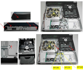
* Power on TV by AC, at the same time press “power on” key which on the boardfor 10s until the TCL logo show.
* 'Factory Hotkey' will be ON automatic.

If “Factory hotkey” is enabled, just press RCU “Return” keyto pop-up again the Factory menu.
The status of “Factory hotkey” can be changed in “Factory menu->Factory hotkey
Press RCU Ok”key to enter the submenu.
Press RCU “Menu” key to go back to the root menu.
Press RCU “◄/” key to change the values.
Press RCU “OK” key run the function.
Press RCU “Exit” key exit the Factory menu.

Factory Captions Description
While “Factory hotkey” is enabled, there’re some toggled display information (~2s) relative to SW, ProjectID, CI+, Network ID to facilitate 100% quick screening without accessing to whatever else menu:

MV (Main SW Version)
ID (Project ID)
Panel ID
MEMC (FRC SW Version)
MID(Internet info for factory)
P (Production - Factory mode flag) S (Factory UART Parser mode flag) W (Warm-Up mode flag)

How to enter Main Menu
* Press RCU “MENU” key to display main menu
* Select “Settings>
Picture>Advanced setting> Contrast”, Scroll down to “Contrast” item
* Press the subsequence RCU keys “
1”, “9”, “5” and “0
* Then the Main Menu will be displayed on the screen.

Warm-up Test
Following TCL standard and practices, it’s required minimum 15min of Warm-Up that can be considered as Burn-In.
Additional Aging for White Balance alignment is no more necessary due to consistent Picture Performance with Cloning usage.
First you need to enable Factory Key. After that selecting“ Factory menu >
WARM UP”, pressing RCU “OK ►” key and then leaving Factory menu by pressing “Exit” key. To release/disable Burn-in mode, it’s just required to press “Menu” button from local keyboard. Other faster methods via UART/IR commands are available on enclosed SIACP
requirements (rev. v8.31)

White Balance & Automatic Gamma correction
For the white balance & automatic gamma correction, we only need do one of them based on the value of
Align-mode in PDM system or the method gave by AOE or R&D.
The detail instruction of Align-mode is as below table:

Align mode                       WB alignment of Auto gamma correction              0 > WG alignment

                                                                                                                                  1 > Gamma correction

White Balance alignment (Golden sample)
As some color coordinates discrepancies can be noticed from panel batches to others, it may necessary to perform slight touch-up.
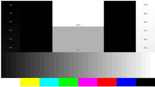
For Color temperature adjustment, switch TV on leading HDMI input where should be connected suitable generator providing following format 1280x720p@60Hz test pattern. A 32 steps grey scale is recommended to assess relevant colorimetry tracking and low or high light saturation points.

Ensure that TV’s picture enhance is off.
Ensure that TV is in Factory mode to access to” White Balance” adjustment submenu.
WB Normal is the first mode which is adjusted in HDMI source
the next are HDMI warm and cool mode.
Warm and Cool Tone are relatives to Normal mode. WB adjust need to fix default G Gain .Offset registers needn’t to be adjusted.
“Gain” registers set need to be adjusted at 70IRE.
Note: The operation must enable factory “P” mode
Auutomatic Gamma correction
Gamma correction, or often simply gamma, is the name of a nonlinear operation used to encode and decode luminance or tristimulus values in video or still image systems.
You need adjust 4+3 gamma for different samples based on the color coordinates and target gamma offered by PQ engineer. So each sample can get almost the same effect as PQ golden sample. The 4+3 gamma include 4 gamma based on 4 different color temperature (cool, normal, warm1, warm2) and 3 gamma related to SDR to HDR (cool, normal, warm).
For the automatic gamma correction, we can do as below, but please refer to “Gamma correction specification (v1.00)”for detail.
* Initialize the picture, turn off dynamic backlight, dynamic contrast, and set picture mode as computer desktop mode;
* Get the color coordinates (x, y, Y) and target gamma in the PDM of the target model;
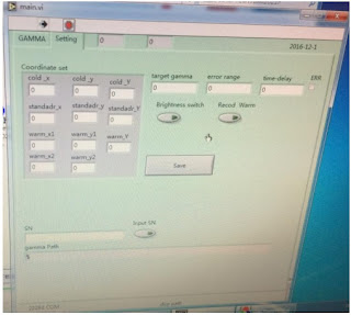
* Open the factory menu of TV, Open the tools SIACP and main.vi on the PC, connect the equipment correctly (CA310, serial port, PC, TV);
* Fill the color coordinates (x, y, Y) target gamma, error range and time-delay in the main.vi tool that made by AOE, and save it;

Put the probe on the middle of the panel, and then run main.vi. The 4+3 gamma will be created and calibrated automatically and saved in the TV.
As 4+3 gamma is a new and good way for PQ especially for HDR, we need adjust it in the factory now. And if we do the 4+3 gamma, there is no need to adjust the white balance. But we need do the initial setup of white balance.
How to do initial setup of white balance”
Note: The operation must enable factory “P” mode
Targets and Tolerances for all inputs
(According to company uniform LED color temperature standard of panel)
The measured and adjustable parameters should be mainly “x”, “y” coordinates.
The White Balance alignment and Automatic Gamma correction should be performed using a well calibrated and contact less analyzer (ex: Minolta CA210 or CA310). The analyzer may not touch the screen surface, and measurement must be performed in a dark environment keeping the probe(s) at 90+/-2° from the panel centre.
The results should fulfil specification for each TV set offered by R&D and below tolerances:

For the 4+3 gamma the target value is 2.2 and error range is ± 0.05.
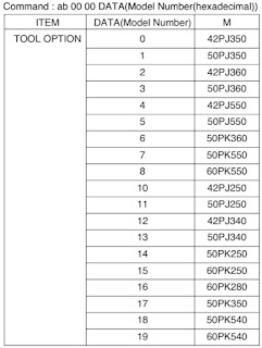
Note
:We will add more project ID later.
Note:
If we can do both of White Balance & Automatic Gamma correction. For some special models, please notice the information provided by Huizhou factory or PJM to choose which way to make it.

Cloning
Once a TV is well aligned and prepared (channels maps, volume, picture presets, …) , user can prepare golden clone image that can be copied on demand to all further TV production lot of same TV. To access cloning function, you can select “Factory menu USB Clone >All -Chanel List - EEPROM - Users Setting” , Scroll down to “TV to USB” or “USB to TV” and press RCU “OK ►” key to process. 4 BIN images can created, overwritten or read on USB stick (pen drive) depending on chosen template like following: “database-applications-database-***.db” . These files need to be used strictly with MT58SoC platform as depending on SW structure.
Other faster access methods via UART/IR command share available on enclosed SIACP requirements (rev. v8.31).
Note: This function is only useful on factory sita P mode. And in hotel mode, we can use it too, but only copy the information related to the hotel.
High Pot. and Insulating Resistance Tests
At the end of the process, a “High Voltage” and an “Insulating Resistance” tests are required to fulfil Safety
Electrical requirements (CEI 65065).
High Voltage Withstanding requirements --
Insulating Resistance requirements
“Voltage” > 3500VAC - “Voltage” > 500VDC
“Max Leakage Current” > 10 mA - “Threshold Min” >4M Ω
“Test Time” >3 sec - “Test Time” >2 sec

At final process stage, it’s necessary to perform “Reset shop” before any packing to leave Factory mode and restore User default presets.
First you need to enable Factory Key. After that selecting “Factory menu
àReset Shop”, then pressing RCU “OK ►” key. Other faster methods via UART-IR commands are available on enclosed SIACP requirements (rev. v8.31).
Note
:A password might be required in case of Parental Control function is locked, use default “1234” password or “0423” super password to clean-up existing ones if forgotten.

“How to upgrade main SW using tool”
Upgrade RT2841 main SW by using RTK tool
Download boot bin “dvrboot.rescue.exe.bin.bin” &main software “Update.img” from the software route.
Connect UART interface to suitable manufacturing TV input connector, upgrade boot bin first to blank IC.
1) Turn off your TV, and then connect the Serial Interface to USB debug port.
2) Open the rtice software, select the Burn page, click the icon, and enter the boot burn page as shown below

3) Click the settings icon, open the settings page, and configure it as shown below

Connect Type select RS232;
Comm port selects the corresponding serial port;
Set-Status type option ROM Code;
IC Type Selection Macarthur5;
Then click ok.
4) Configure Burn parameters and select bootcode load path, as shown below.

5) Click the Start button to enter the boot state and the state will change to the connect state as shown above.

6) Then power on the TV. After the connection is successful, the TV enters the upgrade state and waits for the upgrade to complete. After the upgrade is complete, the following figure shows the bootcode successfully burned.

Then Upgrade Main SW , Copy Main SW “Update.img” into USB stick (pen drive) root path
> Insert USB to TV USB port, long press the “MENU-STB” button of local keyboard , and then Power on TV by AC, The light of IR will flicker, it means TV is updating SW.
> After finish update SW, TV will reboot automatically and please remove the USB.

 “How to upgrade SW using USB”
Upgrade RT2841 main SW
* Copy the “Update.img” into USB stick (pen drive) root path.
* Please delete other xxx.img files from USB stick.
* Plug USB stick to the TV.
* Power on TV by AC, at the same time press “power on” key for 10s, TV will update SW automatically.
* When reflashing is successful, TV should restart automatically (about 4min).
Note
:If “upgrade” was performed, a “Welcome Setup” menu should be displayed, otherwise new SW version should be displayed into relevant Factory mode caption info or on bottom of “Factory menu“
If the P mode is reflashing after upgrade and can not be closed, go to “Factory menu” and select ‘Sita P mode’ to ON, restart TV. Then go to “Factory menu” again and select ‘Factory hotkey’ to OFF.

“How to upgrade SW using USB and RCU”
 “How to upgrade FLASH SW by OAD”
not support now
 “How to change Project ID with RCU”

Enable Factory Key (See “section 2.0-Product Assembly”)
* Process following subsequence IR codes to change project ID:
(xxx: Project ID, ex: 001)

If it works, the TV will restart automatically.

 “How to upgrade CI Key using USB”
* Enable Factory Key
* Create the folder named “CIKEY”, change the CI key to “CIKEY-xxx.bin” (xxx is the number), put CI key into the folder.
* Plus the USB into the TV.
* Go to “Main menu
àService menuàUSB Update >CI Key Upgrade “, click the right button.
* If the toast show CI Update OK, it means burn the key success.
After burning, the CI key will movie to the folder CIKEY>BACKUP.
Note: The operation must enable factory “P” mode
Note
: If unfortunately the process failed, you may need to download new CI key and repeat operation again.

“How to upgrade Widevine Key using USB”
* Enable Factory Key
* Create the folder named “WIDEVINEKEY”, change the Widevine key to “WIDEVINE-xxx.bin”(xxx is the number), put Widevine key into the folder.
* Plus the USB into the TV.
* Go to “Main menu
à > Service menu USB Update > Widevine Key Upgrade “, click the right button.
* If the toast show Widevine Update OK, it means burn the key success.
* After burning, the Widevine key will movie to the folder WIDEVINEKEY-BACKUP.
Note: The operation must enable factory “P” mode

“How to upgrade HDCP key using USB”
HDCP
* Create the folder named “HDCP”, change the HDCP key to “HDCP-xxx.bin”(xxx is the number), put HDCP key into the folder.
* Enable Factory Key
* Plus the USB into the TV.
* Go to “Main menu
 > Service menu >  USB Update >[HDCP] Upgrade“, click the right button.
* If the toast shows HDCP Update OK, it means burn the key success.

After burning, the HDCP key will movie to the folder HDCP-BACKUP

“How to upgrade MAC Address using USB”
* Create the folder named “MAC”, change the MAC key to “MAC-xxx.bin”(xxx is the number), put MAC key into the folder.
* Enable Factory Key
* Plus the USB into the TV.
* Go to “Main menu>
Service menu> USB Update >  MAC Upgrade“, click the right button.
* If the toast show MAC Update OK, it means burn the key success.
* After burning, the MAC key will movie to the folder MAC-BACKUP.
Note
: There is no this function which is only displaying.

 “Network Connection Setup”
Note
:You can set up your TV so that it can access the Internet through your local area network (LAN) using a wired or wireless connection.
Wired Network Connection
You can connect your TV to your LAN using cable in three ways:
1) Plug your TV to your LAN by connecting the LAN port on your TV to an external modem using a Cat5 cable.
2) Plug your TV to your LAN by connecting the LAN port on your TV to an IP Sharer which is connected to an external modem. Use Cat5 cable for the connection
3) Depending on how your network is configured, you may be able to plug your TV to your LAN by connecting the LAN port on your TV directly to a network wall outlet using a Cat5 cable (Note that the wall outlet is attached to a modem or router elsewhere in your house)
4) Select “Menu >Network Settings>
Ethernet” to check if the network has connected. If not then select “IP settings” to connect to network.

Wireless Network Connection
To connect your TV to your wireless network, you need a wireless router or modem and a Wireless LAN Adapter.
* Select “Menu > Network Settings> Wi-Fi-On”, then it will appear the valid wireless networks near your area.
* Select available access point and press “OK ►” to connect the TV to it.
Note
: If you select a protected access point, you will have to enter the corresponding password. Press “OKon the remote control to display virtual keyboard to enable you to enter the password.

Network Setup
* Connect your TV and the available network with the network cable first.

Press on the remote control and select “Network Settings > Ethernet” to check if the network has connected.

If connected, the Internet connection will display Connected. If not, If not it will display “Not Connected” and you can try to enter your IP address manually to connect the network follow below steps
* Select “Advanced options
>IP Settings>Static” by pressing “OK ►” key
* Enter the “IP address”, “Gateway”, “Network prefix length”, “DNS1”and “DNS2”values. Use remote control digital keys to enter number sand “◄/►” key to move from one to other field location
* After setting all required inputs and save successful, to check the Internet connectivity again
* Select
 then press “OK ►” key to display current connection details, such as Internet connection status, IP address, MAC address etc

“How to do initial setup of white balance”
Firstly, you need to enable Factory Key:
* Press RCU “MENU” key to display main menu
* Select “Settings
Picture Advanced setting Contrast”, Scroll down to “Contrast” item
* Press the subsequence RCU keys “
9”, “7”, “3” and “5
* Select “9-Sita P mode”, Press RCU “◄/►” key change the values to ON
* Reboot TV
* 'Factory Hotkey' will be ON automatic.
Secondly, press RCU Option, Select Picture
Advanced setting Contrast Press RCU “1950” enterdesign main menu Reset all


ILO 26HD L5991, ILO 26HD L 6561D – NCP 1203D6 SMPS and LYP 03008A0 KPL OA1 SMPS (power supply board schematic)

$
0
0


LYP 03008A0 KPL OA1 SMPS (power supply board schematic)

ILO 26HD L5991, ILO 26HD L 6561D – NCP 1203D6 SMPS (Power Supply board schematic): Used ICs – LYP0300L6561D, NCP1203D6, L5991, AP4310AM-B 


Viewing all 2033 articles
Browse latest View live


<script src="https://jsc.adskeeper.com/r/s/rssing.com.1596347.js" async> </script>