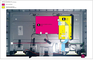
C48P1FS-MT56CT-AP – TCL 48 inch Curved LED TV – service mode – service adjustments – software upgrade – audio output and SMPS circuit diagram
MT56-AP chassis are designed for Asia & Pacific (AP) market Ready for Smart TV. It features by its high integration, easy debugging (ADC adjustment free) as well as convenience in terms of maintenance. Fast software upgrade through USB disk facilitates both manufacture and after-sale service.
Note: Factory Main Menu (FMM) is divided into Factory menu and Design menu. Factory Menu covers all indispensable functions during manufacture such as White Balance Adjustment, SHOP etc., while Design Menu includes Service Menu, Hotel Menu, Param
Setting, Other Setting etc. Some settings like Param Setting and Other Setting is exclusively used by R&D engineer, anyone else shouldn’t change the settings in the menu. When you wish to learn the product information like project ID, project name, Hardware, software version, release date, you can access to Service Menu. In addition, in Hotel Menu, we also provide a great deal of useful functions for specific applications in hotel.
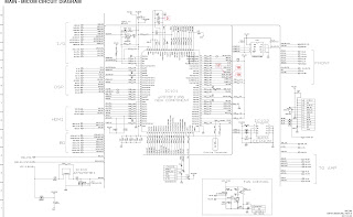
The main chip is from REALTEK and supports below features matrix:
Factory Test & Alignment Specification For MT56-AP Series (V1.0)
The software boot for U702 can be programed by Flash Tool.exe.
Every set has its unique HDCP key which is purchased from suppliers or HDCP certification authority. Please check HDCP function in the process of production.
Once in a while, the software of main board may be upgraded. Please pay attention to use the latest software before production.
Factory Menu
Factory Menu is mainly used for factory production and satisfies various demands of customers. It covers all indispensable functions during manufacture such as Warm up, White Balance, Shop, NVM Reset, Power on mode, USB Clone etc.
Accessing Way
a. When the Factory hotkey item of Factory Menu is disabled (OFF), press Menu button of remote control, then select Settings/Picture, make sure the cursor stop on Contrast item submenu. Finally, press 9, 7, 3, 5consecutively.
b. When the Factory hotkey item of Factory Menu is enabled (ON, you can see the flashing Factory
Captions Info on the lower left corner), press Back button of remote control.
Press RCU “OK” key to enter the submenu.
Press RCU “Right” or “Left” key to change the values.
Press RCU “Right” or “Left” key run the function.
Press RCU “Back” or “Menu” key exit the Factory menu.
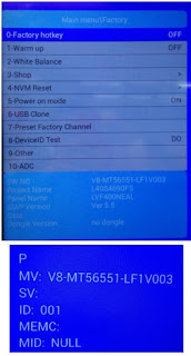
Factory Captions Info:
While “FactoryKey” is enabled, there is some toggled display information relative to MV, SV, ID, MID, to facilitate 100% quick screening without accessing to whatever else menu:
P (Production/Factory mode flag)
MV (Mboot SW Version)
SV (Main SW Version)
ID (Project ID)
MEMC
Factory menu
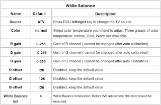
White Balance Menu
Press the button on remote control to select certain item and OK to adjust White Balance.
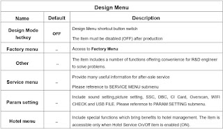
Design Menu includes Factory Menu, other, Service Menu, Param Setting, Hotel Menu.
Some settings like Param Setting and Other Menu is exclusively used by R&D engineer, anyone else shouldn’t change the settings in the menu. When you wish to learn the product information like project ID, project name, chassis name, software version, release date, you can access to Service Menu. In addition, in Hotel Menu, we also provide a great deal of useful functions for specific applications in hotel.
![]()
Accessing Way
a. When the Design mode hotkey item is disabled(OFF), press Menu button of remote control, then select Settings/ Picture, make sure the cursor stop on Contrast item submenu, press 1, 9, 5, 0consecutively.
b. When the Design mode hotkey item of Design Menu is enabled (ON, you can see the flashing Factory Captions Info on the lower left corner), press Back button of remote control.
Press RCU OK key to enter the submenu.
Press RCU Right/Left key to change the values.
Press RCU Right/Left key run the function.
Press RCU Back/Menu key exit the Factory menu.
Design Captions Information is the same to Factory Captions Info.
Other Menu
The Other Menu contains some TV basic information, with which we can check the TV setting before production.
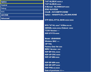
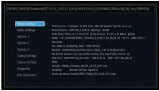
Service Menu
Service Menu contains some basic information of the device, such as Project ID, Hardware, Software version, USB Update etc. This menu is especially useful for after-sale service.
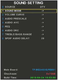
Param (Parameter) Setting Menu
Param Setting menu contains Sound Setting, Picture Curve, Picture Setting, SSC, DBC, CI Card, Over scan, WIFI CHECK and USB FILE. But it is exclusively used by R&D engineer, anyone else shouldn’t change the settings in the menu.
All tests and measurements mentioned hereafter have to be carried out at a normal mains voltage (100 ~ 240 VAC)
All tests and measurements mentioned hereafter have to be carried out at a normal mains voltage (100 ~ 240 VAC)
All voltages have to be measured with respect to ground, unless otherwise stated All final tests have to be done on a complete set including LCD panel in a room with temperature of 25+/-7°C
The Picture Performance assessment such as White Balance (luminance and colour temperature) has to be performed into subdued lighted room after at least 60min of warm-up in order to avoid any temperature drift influence (colorimetry vs time).
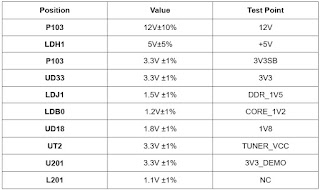
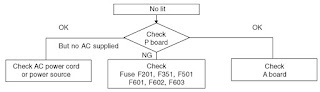
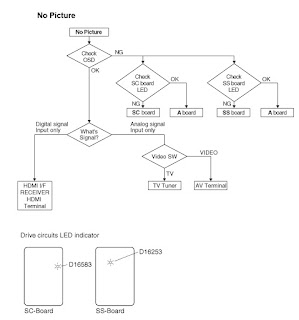
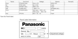
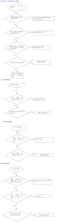
Pre-Conditions and Power Supply Check
Before power-on, please check the board according to the relevant block diagram and circuit diagram, make sure that no serious issue or mistake can destroy the board. For example, the output of DC/DC and LDO should not be shorted to ground.
Supply a suited voltage and power-on, then check the voltage according to the relevant block diagram, circuit diagram and voltage spec, the error should be less than 5%, for example, the voltage for main chip (+3V3, +2.5V, VDDC1V15, 1V5_DDR, etc.), the voltage for TUNER (TU_3V3), the voltage for amplifier (AMP_VCC), etc.
Project ID Modification
There are different ID stored in the EMMC depending on different Panels settings and Model features, but there’s only one key branching Project ID able to ensure normal display. And when you power on the TV set, you should make sure the Project ID is accord with the BOM description. If not, you need to modify the ID. There are two methods to modify the ID:
Change Project ID in Design Menu
In case of “Design mode hotkey” is enabled, press “Back” button to enter Design Menu. To modify Project ID, you need to go through “Service menuàProject ID”, then press Left or Right key to select suitable ID (Project name is dynamically refreshed). Finally restart the TV set.
In case of “Design mode hotkey” is unabled, you can enter the Design Menu easily with reference to 3.1 Design Menu.
Change Project ID with RCU
Press “062598”+”Menu”+”XXX”(XXX represents project ID you’d like to switch to) in the remote control and wait about half minutes, When the set restart automatically, you have successfully changed project ID.
Here below is none exhaustive ProjectID table for reference:
Function Test
Once the Project ID is correct and the TV display normally, plug all external generator devices to relevant inputs/outputs below according to their respective test patterns format and check picture content and sound quality accordingly:
LAN/WLAN Test: MAC Address Upgrade
Upgrading MAC address needs to use the tool in factory and through serial command. The specific method is according to the operation of the factory guidance.
DeviceID (DID) and UserID (UID)
Purpose is to allow Other Network Download (OND) and further specific services over dedicated portal based on AP. For such, specific DID (32 bytes) and UID (8 bytes) needs to be paired and overwritten into memory for internal client encryption, as below:
Those DID/UID codes can only be set using UART commands following enclosed SIACP requirements (rev. v3.9).
LAN Test
A rough LAN test can be done by connecting Ethernet to TV’s RJ45 and check that IP, subnet mask, DNS addresses, which are visible on “HomeàSettingsàNetworkàEthernet settingsàIP settings” (ensure that “Internet Connection” is Enabled at first). More in-depth test can be performed faster using suitable UART/IR commands following SIACP requirements. SW will internally manage Network ID (NID) flag controlling all MAC/DID/UID integrity to facilitate PA screening further.
SHOP INIT (Intilization)
At final process stage, it’s necessary to perform Shop init before any packing to leave Factory mode and restore User default presets according to the requirement of order.
This function is accessible by selecting “Factory Menu à Shop”, then pressing RCU “Right ”or” Left” key. Other faster methods are available on above enclosed SIACP requirements (rev. v3.9).
Warm-up Test
Following TCL standard and practices, it’s required minimum 15min of Warm-Up that can be considered as Burn-In. Additional aging for White Balance alignment is no more necessary due to consistent picture performance with cloning usage. This function is accessible by selecting “Factory menu à Warm up”, pressing RCU “Right” or ”Left” key to set it ON, and then it enter in Warm up mode. Press “Menu” key on keyboard to exit the burning mode. Other faster methods are available on above enclosed SIACP requirements (rev. v3.9)
Software Upgrade: How to upgrade Mboot
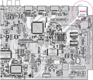
Connect the computer and mainboard VGA port by a serial port tool. Serial connector definition: VGA/P303: Pin4: RXD VGA Pin11:TXD
Open MTK “Mboot” software programming tool “Flash Tool”, and set serial port.
Import the mboot file, as below
power on the TV, then Click Upgrade key and you will see the below message.
How to upgrade FLASH Software
1. USB Upgrade Download the update file (generally named V8-MT56551-LF1VXXX.pkg) to the root directory of your USB device, and make sure there’s no other bin file named analogously. Then insert the USB device to USB interface of TV set.
Power on the TV set, Press and hold on the menu key of key board at the same time. If the TV is updating, you’ll see the screen:
Upgrade process takes about 3~5 minutes.
After updating, the TV set will reset automatically.
Online Upgrade
Download the bin zip file “V8-MT56551-LF1VXXX.Zip” to the root directory of your USB device, and do not change the file name. Then insert the USB device to USB interface of TV set.
Press RCU Menu/Settings/Picture/Contrast/1,9,5,0/Service menu/USB Update /Main
Upgrade/Local Update . If the upgrade file is found, TV will give a message that it verifying. TV displays a warning message, it means selecting “confirm” to continue or “cancel” to exit. During updating, do not power off the TV set.
After updating, the TV set will reset automatically.
Network Connection
You can set up your TV so that it can access the Internet through your local area network (LAN) using a wired or wireless connection.
Connect to a wired network
Attach the TV set to your LAN using cable in three ways:
Connecting the LAN port on the TV to an external modem using a Cat 5 cable.
Connecting the LAN port on the TV to an IP Sharer which is connected to an external modem. Use Cat 5 cable for the connection.
Depending on how your network is configured, you may be able to attach the TV to your LAN by connecting the LAN port on your TV directly to a network wall outlet using a network cable. Note that the wall outlet is attached to a modem or router anywhere in your house.
Select Home → Settings → Network → Ethernet Settings →IP Settings, then the TV will obtain IP address Automatic configuration. In addition, you can set the IP address and password manually.
Connecting to a wireless network
To connect the TV set to your network wirelessly, you need a wireless router or modem and a Wireless LAN Adapter.
If the TV set is equiped with an internal WiFi module, select Home → Settings → Network → Wireless Settings, then turn on Wireless Switch, select a wireless network and press OK to connect.
If you want to connect the TV set to a wireless network by a Wireless High Gain USB Adapter (USB dongle), select Home → Settings → Network → Wireless Settings, then turn on Wireless Switch and External WiFi, and select a wireless network and press OK to connect.
White Balance (WB) Adjustment
The White Balance generally is customized by PQ engineer, and uploaded to the PDM system, anyone else shouldn’t change the value in the menu. If it is necessary to adjust, the following content can offer some reference, but the process of adjusting White Balance is out of the range of this file.
Calibration of Color Temperature
According to TCL standards, the color temperature and white reference coordinates of LCD like the following table: (This standard is based on CA-310 color temperature meter)
White balance adjustment takes the Normal color temperature of HDMI channel as the reference.
Warm and Cold tone is relative to Normal mode. The adjustable gain range is 0~255.
The Normal color temperature of other channel is relative to the Normal mode of HDMI channel. The adjustable gain range is also 0~255.
The manual adjustment is according to the regulation above. Additionally, when manually adjust, it needs to do White Balance init first.
Take signal generator 22293 as an example, the timing value and pattern value of each source show in the following table:
Note:
1) The input signal is 80% white when the pattern value of 22293 is 103.
2) The adjustment of White Balance should fulfill TCL matching specification.
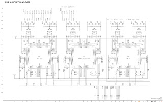
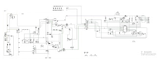
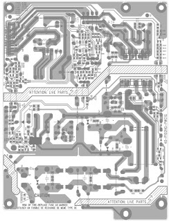
Audio output schematic
SMPS (Power) schematic