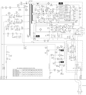
CLICK ON SCHEMATICS TO ZOOM IN

- Self-check is used to automatically check the bus lines and hexadecimal code of the TV set.
- To enter Self-Check mode. Press the down (-/v) button on the customer controls at the front of the TV set, at the same time pressing the STATUS button on the remote control.
- To exit Self Check, switch off the TV set at the power button.
Self-Check should only be used when refurbishing the TV set and not during normal repair work.