Click on the pictures to Zoom.
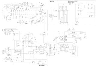
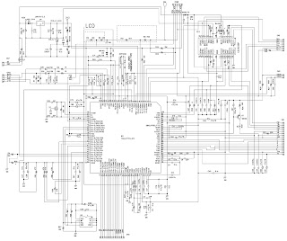
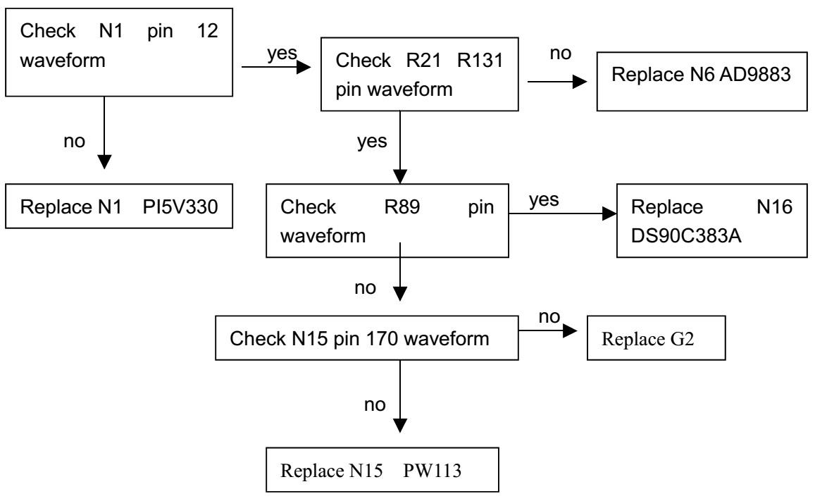
115V ELECTRICAL SCHEMATIC

Picture is out of focus or jumping | * Bad status in signal receiving * Maybe broadcast signal itself is not good * Check if the outdoor antenna is disconnected. * Check if the antenna is correctly oriented. |
Fringe in picture | * Check if the antenna is correctly oriented. * Maybe there is electric wave reflected from hilltop or building. |
Picture is interfered by stripe shaped bright spots | * Possibly due to interference from automobile, train, high voltage transmission line, neon lamp etc. * Maybe there is interference between antenna and power supply line. Please try to separate them in a longer distance. |
Appear streaks or light color on the screen | * Check if interfered by other equipment and if interfered possibly by the equipment like transmitting antenna, non Professional radio station and cellular phone. |
Unable to switch the power on | * Check to see if the power plug has been inserted properly into the socket |
No picture and sound | * Check to see if the power supply of liquid crystal TV has been switched on. (as can be indicated by the red LED at the front of the TV set) * See if it’s receiving the signal that is transmitted from other source than the station * Check if it’s connected to the wrong terminal or if the input mode is correct. * Check if the signal cable connection between video frequency source and the liquid crystal TV set is correct. |
Deterioration of color phase or color tone | Check if all the picture setups have been corrected. |
Screen position or size is not proper | Check is the screen position and size is correctly set up |
Picture color changed or colorless | Check the “Component” or”RGB”settings of the liquid crystal TV set and make proper adjustment according to the signal types. |
Picture too bright and there is distortion in the brightest area | * Check if the contrast setting is too high. * Possibly the output quality of DVD broadcaster is set too high. * It maybe also due to improper terminal connection of the video frequency signal in a certain position of the system. |
Picture is whitish or too bright in the darkest area of the picture | * Check if the setting for the brightness is too high * Possibly the brightness grade of DVD player (broadcaster) is set too high. |
No picture or signal produced from the displayer if “XXX in search” appears. | * Check if the cable is disconnected. * Check if it’s connected to the proper terminal or if the input mode is correct. |
Appears an indication “outside the receivable scope” | Check if the TV set can receive input signal. The signal is not correctly identified and VGA format is beyond the specified scope. |
Remote control cannot work properly | * Check if the batteries are installed in the reverse order. * Check if the battery is effective. * Check the distance or angle from the monitor. * Check if there is any obstruct between the remote control and the TV set. * Check if the remote control signal- receiving window is exposed to strong fluorescence. |
No picture and sound, but only hash. | Check if the antenna cable is correctly connected, or if it has received the video signal correctly. |
Blur picture | * Check if the antenna cable is correctly connected. * Of if it has received the right video signal. |
No sound | * Check if the “mute” audio frequency setting is selected. * Check if the sound volume is set to minimum. * Make sure the earphone is not connected. * Check if the cable connection is loose. |
When playing VHS picture search tape, there are lines at the top or bottom of the picture. | When being played or in pause VHS picture search tape sometimes can’t provide stable picture, which may lead to incorrect display of the liquid crystal TVIn this case please press “auto” key on the remote control so as to enable the liquid crystal TV set to recheck the signal and then to display correct picture signal |