To install the sieve beds, follow the sieve bed removal procedure in reverse order. It is very important to tighten all tubes to eliminate leaks. However, do not over tighten.
To check for leaks, take the following steps:
- Plug in the unit.
- Set the unit’s I/0 (ON/OFF) switch to I (ON) for three minutes with the flow meter closed to pressurize the system.
- Apply soapy water around the hose connections at the valve and the air tank; check for leaks.
Caution: There is an electrical shock hazard with the Power ON. Be careful that no water contacts any of the electrical connections.NOTE: Even small leaks can affect concentrator performance and can cause contamination of the sieve. Careful leak testing is important.
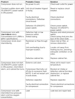
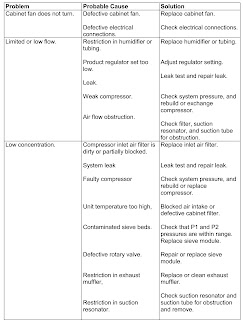
TROUBLESHOOTING
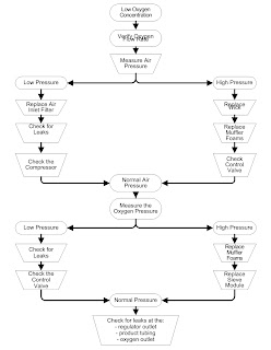
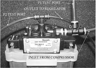
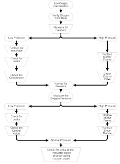
Air Pressure Test (P1)
Testing the operating pressure is a useful diagnostic tool when a concentrator has low purity and requires servicing. Units functioning normally do not require operating tests. Use the following procedure to test the operating pressure of the unit.
- Set the I/0 (ON/OFF) switch to the 0 (OFF) position, and unplug the power cord.
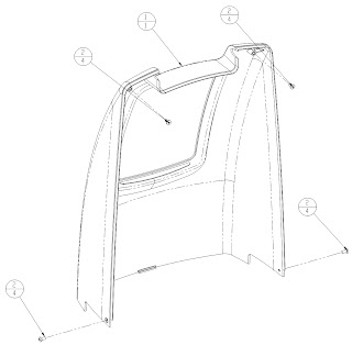
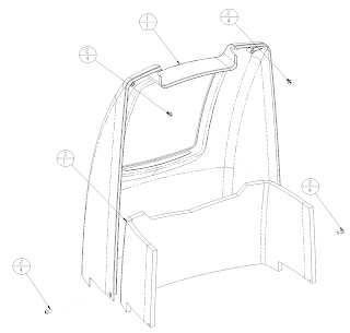
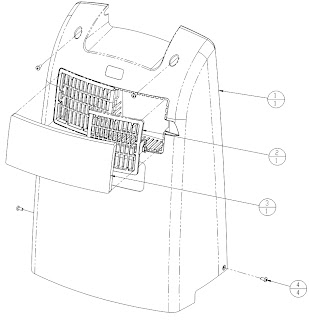
- Remove the cabinet rear.
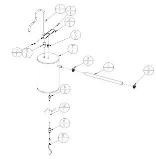
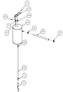
- Remove the test port plug at the top of the air tank.
- Connect the pressure test gauge to the test port.
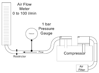
- Plug in the power cord, and set the I/0 (ON/OFF) power switch to the ON position. Set the flow meter to 5 l/min, and allow the unit to run at least five minutes.
- Observe the maximum and minimum readings on the pressure test gauge.
- The maximum reading should not exceed 34 psig (235 kPa). The minimum reading should not be less than 16 psig (110 kPa).
When you turn the unit on, it will take several minutes to reach normal operating pressures.Higher than normal operating pressure may indicate any of the following:
► A restrictive exhaust muffler, which does not allow the waste (purge) gas to exit the system freely. Operate the unit with the exhaust muffler disconnected to see if the operating pressure returns to normal.
► An improperly operating control valve, confirm that the control valve is turning at 4 rpm. Time the exhaust pulse at 7.5 seconds.
► Contaminated sieve beds. Change the sieve beds.
Lower than normal operating pressure may indicate any of the following:
► A restriction in the suction resonator or inlet air filter, which limits the amount of room air available to the compressor. Disconnect the suction tube at the compressor, and allow the unit to operate without the suction resonator to see if normal operating pressure returns.
► An improperly operating control valve. Confirm that the control valve does not have a leak.
► A leak in the unit, which allows system pressure to escape. Leak test the unit.
► A compressor with reduced output. Ensure that the concentration level at the desired liter flow is within specifications
Product Pressure Test (P2)
Testing the product pressure is a useful diagnostic tool when a concentrator has low purity and requires servicing. Units functioning normally do not require operating tests. Use the following procedure to test the product pressure of the unit.
- Set the I/0 (ON/OFF) switch to the 0 (OFF) position, and unplug the power cord.
- Remove the cabinet rear.
- Remove the test port plug from the tee at the top of the sieve bed.
Note: The standard unit without OCSI does not have a test port; use the pressure sensor tube as the test connection.- Connect the pressure test gauge to the P2 test port.
- Plug in the power cord, and set the I/0 (ON/OFF) power switch to the ON position. Set the flow meter to 5 l/min, and allow the unit to run at least five minutes.
- Observe the maximum and minimum readings on the pressure test gauge. The maximum reading should not exceed 16 psig (110 kPa). The minimum reading should not be less than 9 psig (62 kPa).
Low Product PressureLower than normal operating pressure may indicate any of the following:
► An inlet air filter that limits the amount of room air available to the compressor. Disconnect the suction tube at the compressor, and allow the unit to operate without the suction resonator to see if normal operating pressure returns.
► An improperly operating control valve. Confirm that the control valve does not have a leak.
► A leak in the unit, which allows system pressure to escape. Leak test the unit.
► A compressor with reduced output. Ensure that the concentration level at the desired liter flow is within specifications.
High Product Pressure
Higher than normal operating pressure may indicate any of the following:
► A restrictive exhaust muffler, which does not allow the waste (purge) gas to exit the system freely.
► Operate the unit with the exhaust muffler disconnected to see if the operating pressure returns to normal.
► Check exhaust muffler and hoses for any restrictions.
► An improperly operating control valve, confirm that the control valve is turning at 4 rpm. Time the exhaust pulse at 7.5 seconds.
► Contaminated sieve beds. Change the sieve beds.