Quantcast
Channel: Electro help
Viewing all 2033 articles
Browse latest View live

SONY BDP BX18 – S185 – S186 - BLU-RAY DISC PLAYER - SERVICE MODE - Optical device replacement - How to Remove Disc at No Power -

$
0
0
DISC REMOVAL PROCEDURE (FORCED EJECTION)
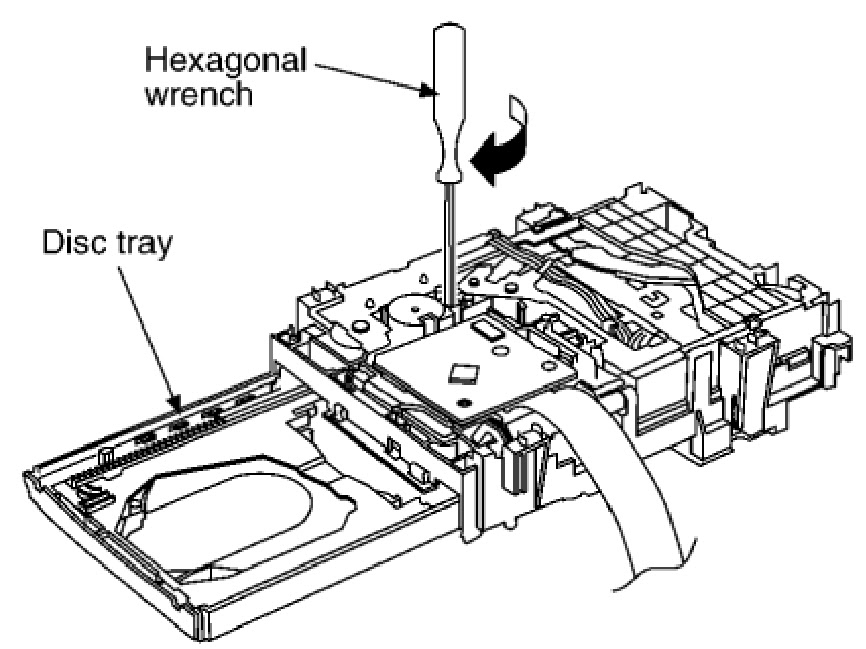
  • Remove the upper case.
  • Insert a clip in the hole of a drive and open a tray.
OPTICAL DEVICE REPLACEMENT
  • Install it in PC after downloading two set of software.
  • Microsoft .NET Framework Version 2.0 Redistributable Package (x86)
  • Microsoft .NET Framework 2.0 Service Pack 1 (x86)
  • Take a photograph of the bar code on the optical device. The valid bar code photo as shown.
  • Drag-and-drop the bar code photograph to the icon of decode software (BDPRdec).
The decode software is a complete set of “BDPRdec”,  “T asman.Bars.dll”, and “SavePath”.
Because decode software cannot be attached, it separately distributes it.
  • Input the password when you start decodes software.
Inquire of each service headquarters because the password cannot be disclosed.
  • Write the decode data to the set.
BEFORE BU REPLACEMNT
{CLICK ON PICTURES TO ZOOM}
BDP 6.9G (B D P-S1 8 5 ) series component structures as sambas conventional DVD Players.  However player requires precise read out functions and also secures contents Protection system.
Since above requirement, it is necessary to set/adjust BU data to EEPROM.
Replace BU(MB is original)
Replace MB (BU is original)
Replace both BU and MB
Requirement
  • Digital camera (recommend with macro mode)
  • Barcode decoder (BDPRdec_ver2.0) installed in JIG PC’s
  • USB memory
  • ESD work bench.
The servo adjustment procedure will be carried out during OP data Writing.  There is no manual adjustment procedure. LD ON TIME history doesn't carry over.
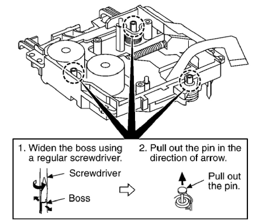
Do not touch any optical block parts, Turn Table and during replacing. BD Laser diode is very sensitive.
BU ADJUSTMENT FLOW
BU Data Decode Jig
JIG Name: BDPRdec. Exe
Release: 2010.11.26
Version : 2.0.0.0
Software Contents:
BDPRdec.exe ; Software
SavePath.ini ; decoded file destination setting file (initial destination is C:¥BuData.txt)
Tasman.Bars.dll ;decode dll
Uninst.exe ; unistall BDPRd ec.exe from PC
Installations
Unzip files to any PC Folder
Check the attached 2D code photo(OK_sample.JPG) drag-and-drop onto BDPRdec.exe, the Password will be required at first time only, no need P/W from second time.
If there is the error message (.NETframe work requirements) please apply Microsoft .NET Framework 2.0 (or 2.0 SP1) from Microsoft download site.


CB20 _ CB21H1T5X_SAMSUNG CRT TV - POWER_CRT_VERTICAL_HORIZONTAL SECTION - SCHEMATIC (Circuit Diagram) [KA7630 – TDA8356 – TDA61070 – KSC5386 – KA3S0680AF(Power Control)]

$
0
0

SCHEMATIC DIAGRAM

Click on Schematic to Zoom

DELL 19" LCD MONITOR_1907FPc - POWER AND INVERTER SCHEMATIC _ STP10NK70ZFP (Power Switching) – LD7552 IC (Power Control) – PC123FY2 4P (Opto-isolator)

$
0
0
POWER [SMPS] SCHEMATIC
INVERTER
CLICK ON PICTURES TO ZOOM

HOW TO DISASSEMBLE DELL 1907FPc_LCD MONITOR

$
0
0
DISASSEMBLE PROCEDURE
  • Rotate the stand to allow access to the stand release button.
  • Press the Stand release button and lift up the Stand and away from the monitor.
  • Remove the 4 screws.
  • Pry the monitor up then find out the hooks’ position, use the tool (like the picture or other card) to insert into the gap of bezel and rear cover.

  • Take off the bezel.
  • Turn over the monitor as the Fig, hold the rear cover, and then slightly remove it.
  • Remove the 4 screws.

  • Remove the USB2 board cover.
  • Remove the 5 screws.
  • Disconnect the wire harness between USB1 and USB2.

  • Push the main shield as the arrowhead direction.
  • Disconnect the connector pin: Disconnect the connector pin between key and main boards.

HOW TO ENTER FACTORY MODE - DELL1907FPc - 19" LCD MONITOR_EDID CONTENT

$
0
0

FACTORY MODE [SERVICE MODE]
Press MENU   and UP button   at the same time, during press power button on will activate the factory mode, then press MENU again, main MENU will be in the middle of the screen.
Gain adjustment:
Move to “Factory Reset” and press MENU key to enter this sub-menu.
Move to “ Factory” and press MENU key.
Move to “ Auto Color” and press MENU key to adjust Gain and Offset automatically;
Adjust sRGB (6500K) color-temperature
  1. Switch the chroma-7120 to RGB-mode (with press “MODE” button)
  2. Switch the MEM.channel to Channel 3 (with up or down arrow on chroma 7120)
  3. The LCD-indicator on chroma 7120 will show x =313±28, y=329±28, Y = 230 ±20 cd/m2
  4. Adjust the RED on OSD window until chroma 7120 indicator reached the value R=100
  5. Adjust the GREEN on OSD, until chroma 7120 indicator reached G=100
  6. Adjust the BLUE on OSD, until chroma 7120 indicator reached B=100
  7. Repeat above procedure (item 5,6,7) until chroma 7120 RGB value meet the tolerance =100±2
Switch the chroma-7120 to RGB-mode (with press “MODE” button)
  • Switch the MEM.channel to Channel 4 (with up or down arrow on chroma 7120)
  • The LCD-indicator on chroma 7120 will show x=283±28, y=297±28, Y = 200 ±20 cd/m2
  • Adjust the RED on OSD window until chroma 7120 indicator reached the value R=100 
  • Adjust the GREEN on OSD, until chroma 7120 indicator reached G=100
  • Adjust the BLUE on OSD, until chroma 7120 indicator reached B=100
  • Repeat above procedure (item 5,6,7)until chroma 7120 RGB value meet the tolerance =100±2.
Adjust Color2 (5700K) color-temperature
  • Switch the chroma-7120 to RGB-mode (with press “MODE” button)
  • Switch the MEM.channel to Channel 9 (with up or down arrow on chroma 7120)
  • The LCD-indicator on chroma 7120 will show x = 328 ±28, y = 344 ±28, Y = 230 ±20 cd/m2
  • Adjust the RED on OSD window until chroma 7120 indicator reached the value R=100
  • Adjust the GREEN on OSD, until chroma 7120 indicator reached G=100
  • Adjust the BLUE on OSD, until chroma 7120 indicator reached B=100
  • Repeat above procedure (item 5,6,7) until chroma 7120 RGB value meet the tolerance =100±2
  • Move cursor to “ Exit/Save” sub-menu and press MENU key to save adjust value and exit.
Turn the POWER-button off to on to quit from factory mode.
EDID CONENT [ANALOG EDID]
CLICK ON TABLES TO ZOOM
DIGITAL EDID

TROUBLESHOOTING FLOW CHART - DELL1907FPc_LCD MONITOR_White Balance Adjustment

$
0
0
TROUBLESHOOT
  1. If replace “Main-Board”, re-do “DDC-content” programmed & “White-Balance”.
  2. If replace “Power Board” only, re-do “ White-Balance”.
White balance, Luminance adjustment
Approximately 30 minutes should be allowed for warm up before proceeding White-Balance adjustment.
Before started adjust white balance, please setting the Chroma-7120 MEM. Channel 3 to 6500K colors, MEM. Channel 4 to 9300K colors, MEM. Channel 9 to 5700K (our 9300 parameter is x=283±28, y=297±28, Y = 200 ±20 cd/m2, 6500 parameter is x =313±28, y=329±28, Y = 230 ±20 cd/m2, and 5700 parameter is x = 328 ±28, y = 344 ±28, Y = 230 ±20 cd/m2)
How to setting MEM.channel
You can reference to chroma 7120 user guide or simple use “ SC” key and “ NEXT” key to modify x, y, Y value and use “ID” key to modify the TEXT description Following is the procedure to do white-balance adjust.
NO POWER
NO PICTURE [LED IS ORANGE]
CLICK ON THE CHARTS TO ZOOM[Click ß at the top left of the browser to come back]
WHITE SCREEN
INVERTER / POWER BOARD [NO POWER]

NO BACK-LIGHT
KEYBOARD

SAMSUNG PLASMA_PL42A450P_PL50A450P (Pyrope) - TROUBLESHOOTING

$
0
0

TROUBLESHOOT
   Check if the Operating LED on the Logic Main blinks at a half second interval.  If the frequency of the blinking is too fast or slow, it means that the MICOM has failed to process the data properly. Therefore, you have to reload the data onto the MICOM. Load the data using GA-WRITER when the power is connected to the module.

  • If no problem is found during the Visual Inspection, check if the drive waveform and the address data outputs are normal using an oscilloscope. (Checkpoint: The DAMPING R-NET part output of each data output terminal.)
  • If no drive waveform or address output is measured, this means that there is a drive problem due to MICOM data corruption, which was the reason in the Visual Inspection. Therefore, in this case, reload the data as you did in the Visual Inspection.
  • When data output is measured but it is abnormal, and the drive waveform is abnormal, it is probably due to a short-circuit of the hardware. If the address data is abnormal, the screen may be abnormal due to abnormal data output by an abnormal operation of the DDR memory due to an abnormal Vref voltage, or the screen may be abnormal due to a short-circuit in the ass'y inside the board. You have to conduct a short-circuit test for each case.
  • If the Vref voltage (the voltage of the Voltage Divider) is lower than 1.25V, check the resistance of the resistance output part and check if the circuit is normal. If the Vref voltage is normal, the screen operates normally.
  • If the screen is abnormal, even though the Vref voltage is normal, check if there is a short circuit by conducting a short-circuit test. If a short-circuit is found, repair it. If the short-circuit is an internal one, replace the board.
NO DISPLAY
{CLICK ON PICTURES TO ZOOM. Click on  ß at the top left of the browser window, to come back}
ABNORMAL DISPLAY
FAULTY SCREEN DISPLAY & POSSIBLE REASONS
A blank vertical cell (block) appears on the screen.
  • Address buffer defect:  Replace the corresponding upper/lower buffers (E, F).
  • COF defect (burnt):  Replace the module.
A green screen appears when the TV is turned on.
  • The Scale is not resetting.  Replace the Main board.
The OSD box appears but there is no text.

  • Incorrect program version:  Check the version of each program.  Replace the Main board.

A blank upper (or lower) block appears on the screen.
Upper/Lower Y Buffer defect.  Replace the corresponding upper/lower buffers (E, F).
Either the main or sub picture does not appear.
Replace the Main board.
A vertical green line appears on the screen.
The SMPS voltage is incorrect.  Adjust the SMPS voltage according to the voltage printed on the module label.
Dim screen (blurred in red).
X-Main board defect:  Replace the X-Main board.
A blank screen appears.
Replace the Y-Main board.
TROUBLESHOOTING PROCEDURES BY ASSEMBLY
  1. SMPS-PDP TV àNo power, Blank screen, the Relay repeats On and Off.
  2. ASSY PDP MODULE P-X-MAIN à Blank screen.
  3. ASSY PDP MODULE P-Y-MAIN à Blank screen.
  4. ASSY PDP MODULE P-LOGIC MAIN à Blank screen, Screen noise.
  5. ASSY PDP MODULE P-X-MAIN BUFFER à Row Bar screen is blank.
  6. ASSY PDP MODULE P-ADDRESS E BUFFER à Corresponding Buffer Board block screen is blank.
  7. ASSY PDP MODULE P-ADDRESS F BUFFERà Corresponding Buffer Board block screen is blank.
  8. ASSY PCB MISC-MAIN àNo Power, Abnormal screen for each input source, PIP screen trouble, Sound trouble.
  9. ASSY BOARD P-FUNCTION à The side function key does not work properly.
  10. ASSY BLUE P àThe side function key does not work properly.  The remote control does not work properly, the LED does not work properly.

                                   42"
                                50"

PL42A450P_PL50A450P _ SAMSUNG PLASMA TV _ ERROR MODES - CHECKPOINTS

$
0
0

CHECK POINTS BY ERROR MODE
Check the power input to the Main Board.
Check the voltage in and out between the SMPS ß> Main Board, between the SMPS ß> X, Y Main Board, and between the Logic Boards.
NO POWER
Symptom: 
  • The LEDs on the front panel do not work when connecting the power cord.
  • The SMPS relay does not work when connecting the power cord.
  • The unit appears to be dead.
Major check-list
The SMPS relay or the LEDs on the front panel does not work when connecting the power cord if the cables are improperly connected or the Main Board or SMPS is not functioning. In this case, check the following:
  • Check the internal cable connection.
  • Check the fuses.
  • Check the output voltage of the SMPS.
  • Replace the Main Board.
CLICK ON TABLES TO ZOOM. [Click ßat the top left of the browser window to come back]

THE UNIT REPEATEDELY SWITCHES ON & OFF
The SMPS relay is repeatedly turning on and off.  In general, the SMPS relay repeatedly turns on and off by the protection function due to a defect on a board connected to the SMPS.
  • Disconnect all cables from the SMPS, operate the SMPS alone and check if the SMPS works properly and if each voltage output is correct.
  • If the symptom continues even when SMPS is operated alone, replace the SMPS.
  • If the symptom is not observed when operating the SMPS alone, find any defective assemblies by connecting the cables one by one.
When separating and connecting the cables such as CN810, CN809, CN808, CN807 of the Main SMPS, CN4701 of the X Main Board, and CN5707 of the Y Main Board, a spark may be generated by the electric charge of the high capacity capacitor. Therefore, wait some time after disconnecting the power cord from the unit.
NO PICTURE.  AUDIO IS NORMAL
  • This may happen when the Main Board is functioning, but the X, Y Main Board, Logic Board, or Y Buffer Boards are not.
  • The output voltage of the Main SMPS.
  • This may happen when the LVDS cable connecting the Main Board and the Logic Board is disconnected.
   When separating and connecting the cables such as CN810, CN809, CN808, CN807 of the Main SMPS, CN4701 of the X Main Board, and CN5707 of the Y Main Board, a spark may be generated by the electric charge of the high capacity capacitor. Therefore, wait some time after disconnecting the power cord from the unit.

NO SOUND - PICTURE IS NORMAL
  • When the speaker connectors are disconnected or damaged.
  • When the sound processing part of the Main Board is not functioning.
  • Speaker defect.
NO VIDEO
  • Check the antenna connection settings (Air: NTSC / ATSC, Cable: NTSC)
  • Check the CVBS cable connection.
  • Check the power input of the Main board.
The above stated faults are almost common to all Plasma TVs, irrespective of Brand and Screen Size.


HOW TO ENTER SERVICE MODE - PANASONIC TX W32D4DP – 32” TV – HOW TO OPEN – ADJUST – DISASSEMBLE

$
0
0

DISASSEMBLE PROCEDURE
Remove 10 screws shown, to remove back cover.
Control locations
Click on pictures to Zoom.   Click ß at the top left of the browser window, to come back.

CHASSIS SERVICE POSITION
  • Hold and lift the rear of the E-PCB chassis and gently pull the chassis toward you, as shown.
  • Release the respective wiring clips and rotate the chassis vertically through 90°, anti-clockwise.
  • Locate the base of the chassis frame into the hole (B)
  • Clip the chassis frame onto the bead clamper
  • After servicing replace the bead clamper and ensure all wiring is returned to its original position.
ADJUSTMENTS
Item / Preparation
Adjustments

+B SET-UP
1. Receive a Grayscale signal.
2.  Set the controls:-Brightness Minimum
Contrast Minimum
Volume Minimum
1. Confirm the following voltages.
D-Board E-Board
D3 PIN5 147V ± 3V U8A E19-PIN8 8V ± 0,5V
D12 PIN5 5V ± 0,3V U9 IC3801-PIN39V ± 0,5V
D13 PIN1 40V ± 4V U12 E22-PIN8 12V ± 0,5V
D3 PIN4 230V ± 10V STD5VE26-PIN4 5V ± 0,5V
D3 PIN4 205V ± 10V U15 E23-PIN8 15V ± 1V
D3 PIN4 190V ± 10V U15 E23-PIN9 -15V ± 1V
D3 PIN4 190V ± 10V U33 E22-PIN10 33V ± 4V
D14 PIN5 5V ± 0,5V U40 E24-PIN1 40V ± 3V
D12 PIN7 15V ± 2V U5B E19-PIN5 5V ± 0,5V
D12 PIN9 15V ± 2V
D11 PIN8 12V ± 2V
D11 PIN1033V ± 3V
Cut Off
1. Receive grayscale signal.
2. Degauss the tube externally.
3. Set the TV into Service Mode 1.
4. Select Cut off mode.
Adjust the screen VR until the display shows "O.K."
FACTORY SETTINGS
To return customer settings to factory settings and clear owner ID of all information input by the customer, enter Self-Check mode. Press the down (-/v) button on the customer controls at the front of the TV set, at the same time pressing the STATUS button on the remote control.
To exit Self Check, switch off the TV set at the power button.
SELF CHECK MODE DISPLAY
Self-Check should only be used when refurbishing the TV set and not during normal repair work.
Self Check is also used to automatically check the bus lines and hexa decimal code of the TV set. If the CCU ports have been checked and found to be incorrect or not located then " - - "will appear in place of" O.K.". For more in-depth TV diagnostics use the LUCI interface listed below.
To aid in the service of current chassis there are a number of Service Aids which have been made available.
LUCI interface kit (Linked Utility Computer Interface)
Part number:TZS6EZ002
This contains interface and cables for connecting TV service connector and a PC as well as diagnostic software. As new models are introduced upgrade software will be come available.
VICI (Visual Interactive Computer Information)
These C.D.'s contain multimedia documentation providing quick access to service information.
Part No. TZS7EZ006 & TZS7EZ005
Service Manuals
Instruction Books
Technical Information
TASMIN (Technically Advanced System for Multimedia Interactive Notes)
As well as providing a first step towards more interactive training this product also achieves quick access to Technical Information.

JBL SUB150 - JBL SUB230 - ACTIVE SUB-WOOFER - SCHEMATIC [Circuit Diagram] - Troubleshooting

$
0
0
POWER SUPPLY - SMPS - THX203H [Power Switching & Control IC]

CLICK ON SCHEMATICS TO ZOOM {Click  ß  at the top left of the browser to come back.}

POWER AMPLIFIER
TROUBLESHOOTING FLOW CHART
PHASE ADJUSTMENT
   The Phase switch determines whether the sub-woofer driver’s piston-like action moves in and out in phase with the satellite speakers. If the sub-woofer were to play out of phase with the satellite speakers, the sound waves from the satellites could partially cancel out the waves from the sub-woofer  reducing bass performance and sonic impact. This phenomenon depends in part on the placement of all the speakers relative to each other in the room. Although in most cases you should leave the Phase switch in the “Normal” position, there is no absolutely correct setting for the Phase switch. When the sub-woofer is properly in phase with the satellite speakers, the sound will be clearer and have maximum impact, and percussive sounds like drums, piano and plucked strings will sound more lifelike. The best way to set the Phase switch is to listen to music that you know well and to set the switch in the position that gives drums and other percussive sounds maximum impact.

JBL - CENEMA BD100 – BD300 - 5.1-channel 3-D Blu-ray home cinema system - POWER SUPPLY SCHEMATIC [Circuit Diagram]

$
0
0

POWER SUPPLY SCHEMATIC
CLICK ON THE PICTURES TO ZOOM. {Click on  ß at the top left of the browser to come back}

SHARP ER A410 - ER A420 - HOW TO UPGRADE READ ONLY MEMORY [ROM]

$
0
0
ROM A410A 420U
MODEL NAME  :  ER-A410, ER-A420
ROM SIZE    :  512KBytes(4Mbits)
FILE NAME   :  A420U_2B.ROM
ROM VERSION :  28F40RCC2B
CHECK SUM   :  A610
ERA 420 ROM LOADING
Sharp has released a new POSUTILITYTOOLS.exe program.
POSUTILITYTOOLS3.exe is to be used to download the ROM image to the ERA410/20 machine follow the procedure below.
The exe file as well as ROM images can be found on the Sharp Technical Web Site.
Procedure to load image via POSutilitytool3 program:
Put ER-A410/20 into IPL Mode, using the following procedure:
  • Turn off the power switch of ER-A420 and turn modeswitch to SRV position.
  • Holding down Receipt paper feed key, Journal paper feed key and Void key, turn on power switch of ER-420.  "IPL" is shown on operator display.  Then you can load the ROM object to ER-A420 by POS utility tool3 via RS232.
TO UPGRADE THE ERA420 ROM IMAGE
Before working on the installation, unplug the AC code from the AC outlet.
  • Open the top cabinet.
  • Set the IPL switch (S1) to ROM COPY position.
  • Install the IPL ROM to the IC socket of the MAIN PWB.
  • Turn the mode key switch to SRV’ position, and insert AC plug in AC outlet.
  • Turn the mode key switch to SRV position. The IPL procedure is started.
When the procedure is completed, the message of “Completed.” Is shown.
CLICK ON PICTURES TO ZOOM.{Click ß at the top left of the browser to come back.}
  • Unplug the AC code from the AC outlet.
  • Remove the IPL ROM to the IC socket of the MAIN PWB.
  • Set the IPL switch (S1) to GND position.
  • Replace the top cabinet.
  • Perform the master reset.
Turn the mode key switch to the SRV’ position, insert AC plug in AC outlet.  While holding down Journal feed key, turn to SRV position from SRV’ position.

SHARP MX FN12 - HOW TO DISASSEMBLE PAPER PASS UNIT - - DIGITAL FULL COLOR MULTIFUNCTIONAL SYSTEM OPTION FINISHER

$
0
0

FINISHER
  • Remove the hand screw from the finisher connection connector on the rear side of the machine, and remove the machine connection harness from the finisher.
  • Open the front cover of the finisher.
  • Turn the separation lever to the left to separate the finisher from the machine. Slide the finisher to the left until it stops.

  • While pushing the lock lever to the bottom, slide the finisher a little to release the lock.
NOTE: To prevent against falling, do not slide the finisher excessively with the lock released.
  • Remove the finisher from the machine connection unit.
NOTE: When holding the finisher, hold the front frame side and the rear frame side together.
PAPER PASS UNIT
Remove the screw, and remove the paper pass unit.
UPPER PAPER GUIDE
Remove the screw, and slide the finisher upper paper guide to the front side to remove.
FRONT CABINET - RIGHT
Remove the screw, and remove the separation lever.
Remove the screw, and remove the front cabinet right.
REAR CABINET & IF MAIN PWB COVER
Remove the screw, and disengage the pawl and remove the rear cabinet.
Remove the screw, and slide the IF main PWB cover to the front side to remove.

HOW TO DISASSEMBLE TOP CABINET – CD LID & REAR PANEL- PANASONIC SA-AK630

$
0
0

TOP CABINET REMOVAL
  • Remove 2 screws at each side and 5 screws at rear panel.
  • Lift up both sides of the top cabinet, push the top cabinet towards the rear and remove the top cabinet.
CD LID DISASSEMBLY
Opening the disc tray automatically (Using Power Supply)
  • Connect the AC power cord.
  • Press the POWER button to power up the main unit.
  • Press the OPEN/CLOSE button, the disc tray will open automatically.
  • Release the 2 claws, and then remove the CD Lid.
  • Press the OPEN/CLOSE button, the disc tray will close.
  • Press the POWER button to turn the power off.
[Opening the disc tray manually (Using service tools)]
  • Insert the gear tool into the hole on the underside of CD chassis and then rotate in the direction of arrow. The disc tray will be opened.
  • Release the 2 claws, and then remove the CD lid cover.
  • Repeat Step 2 but rotate the gear tools in anti-clockwise direction.
  • The disc tray will be closed.

PANASONIC SA AK630 - HOW TO REPLACE BELTS - CAPSTAN BELT - WINDING BELT

$
0
0

MOTOR ASS'Y, CAPSTAN BELT & WINDING BELT REPLACEMENT
  • Release the 2 claws, and then remove the head connector.
  • De-solder plunger point.
  • Remove the Deck Mechanism P.C.B.
CLICK ON PICTURES TO ZOOMClickßat the top of the browser to return.
  • Remove 3 screws.
  • Remove the flywheel R.
  • Release the claw of tape side, and then remove the winding lever and spring.
  • Remove the flywheel F
INSTALLATION OF BELT
  • The boss and marking should be positioned horizontally.
  • Put the winding belt on the pulley temporarily.
  • Install the flywheel F.
  • Put the winding belt on the flywheel F.
  • Install the winding lever and spring while pressing the winding arm in the direction of arrow.
  • Install the flywheel R.
  • Put the capstan belt A temporarily as shown below.
  • Put the capstan belt B on the motor assy’s pulley.
  • Install the sub chassis to the mechanism, and then tighten screws.
  • Remove 3 screws.
  • Put the capstan belt B as shown below.
  • Put the capstan belt A on the motor ass’y pulley.


ERROR CODES - PANASONIC SA AK630 - SELF DIAGNOSIS - CD TEST MODE

$
0
0
CR-20 MECHANISM ERROR CODES
If mechanism problem occurs during normal or aging mode, the error code is “remembered” and shown on the FL display.
Reset Condition of Error Code
a. During cold start of micro-processor IC.
b. Restart of ageing mode for the mechanism unit.
 Mechanism Error Code.
CLICK ON PICTURES TO ZOOM.  Click ßat the top left of the browser to come back.

When the mechanism unit stops due to error during aging model, error code misremembered and counts of the errors are displayed on the FL display.
SELF DIAGNOSIS FUNCTION
To enter self diagnosis mode
Cassette Mechanism Test (For error code H01, H02, H03, F01)
  1. Press “TAPE, DECK 1/2” to select Deck 2.
  2. Load a cassette tape with the erasure prevention tab, remove from left side only and close the cassette holder.
  3. Press “FASTFORWARDMEMORY” (Tape will be stop after 2 seconds)
  4. Load a cassette tape with the erasure prevention tab, remove from right sideonly and close the cassette holder.
  5. Press “REVERSE FM MODE/BP” (Tape will be stop after 2 seconds)
  6. Load a pre-recorded tape with both side record tabs intact and close the cassette holder.
  7. Press “PLAY/TUNE/TIME ADJ UP” (After TPS function, tape will stop automatically)
  8. Press “REC/STOP” (Tape will not move)
  9. Press “STOP/TUNE MODE” to indicate Error code.  If several problem exist, error code will change each time when “n/STOP” is pressed. (e.g. H01 -->H03 -->F01 .....etc.)
  10. Press “TAPE, DECK 1/2” to select Deck 1.
  11. Repeat step 2 to 9 to test Deck 1. (Tape Deck 1 will not check H02 because of no recording function).
CD Mechanism Test (F15, F26, F16, F17, F27, F28, F29, F30, H15 & H16)
  • Press [►/pause, CD]  (set to CD Mode) on main unit.
  • Press “CD DIRECT PLAY (1)” and [Eject, open/close] button on main unit.
  • Press [eject, open/close] to close the tray.
  • Press “CD DIRECT PLAY (5)” and [eject, open/close] wait until the tray is open.
  • Press [eject, open/close] and remove the CD.
  • Press [eject, open/close] to close the tray.
  • Press “n/STOP” to indicate Error Code.   If several problem exist, error code will change each time when “n/STOP” is pressed. (e.g. F15 --> F26 --> F16 ....etc).
TO CLEAR ALL ERROR CODES
  • Press and hold [stop] button for 5 seconds.
  • FL indicator shows “CLEAR” for 1 second and change to “T”
To exitfrom Self-Diagnostic function
Press [Power] button on main unit or remote control.
Power Amplifier Failure (F61)
When power amplifier fail, F61 will indicate automatically.
Abnormality detection for Deck Mechanism
Abnormality detection for CD/Changer
Power supply related error
Error Display: F61
  • During normal operation, if DCDET becomes ‘L’, normal POWER OFF process shall not be executed, PCNT shall be switched to ‘L’ immediately. GOODBYE shall not be displayed and the error display F61 will be displayed instead.  2 seconds after the F61 display, ECONO shall be set to ‘L’ and FL display shall be turned off.
  • The error content shall be memorized when the abnormality occurs and can be displayed in the C-mecha self-diagnostic mode described later.
CD TEST MODE
CD test mode is provided to check CD unit without connecting to changer loading mechanism. This mode shall operate CD PLAY with CD unit being connected only and CD Automatic Alignment result is shown on FL display.
Under CD test mode, pressing the numeric key ‘0’ on the remote controller will display the auto adjustment result. FLOCK, TLOCK and CLVS status shall be shown as below:
During the above display, executing CD PLAY will display auto adjustment result for CD PLAY mode.
CD MECHA AGING TEST MODE
Functional summary of CD aging test mode.  It is for the purpose to determine the reliability of the CD changer.
First, enter into self-diagnostic mode.
In the self-diagnostic mode, switch the SELECTOR to [►/PAUSE, CD] and press [|<</REW/v]. It will enter into CD aging test mode.
When in CD aging test mode, the following operation will begin and repeated:
  1. [DISC STOCKER] àDISC LOAD àTRAY OPEN (2 secs) àTRAY CLOSE] as one count.
  2. DISC 1 àDISC 2 àDISC 3 àDISC 4 àDISC 5 àDISC 1........repeating this endlessly.   While performing the above operation, the FLdisplay will show the number of its operations starting from 00001.
It shall move up one counter when the above operations end. The counter will reset to 00000 when 99999 is reached.  
To exit CD aging test mode, press [POWER] button, the tray will return to its PLAY position and power will be off.
MICON ROM CHECKSUM AND VERSION DISPLAY MODE
To enter into Micon ROM checksum and Version Display Mode.
  • Enter into Self-Diagnostic Mode.
  • In the Self-Diagnostic Mode, Press [►/PAUSE, CD] twice.
The version number and the calculated ROM Checksum of the current software will be displayed on the FL as shown in this example:
The Software Version No. & Micon Software Checksum differs from set to set.
The ROM Checksum is calculated on demand, not hard coded.
The ROM Checksum is calculated by talking the arithmetic SUM of the ROM contents from the program’s START address until the END address.
START address = [1080]H
END address = [FFFD]H

PANASONIC AK 630EE - HOW TO Disassemble CD mechanism – Main PCB – Sub-Power PCB and Power Amplifier IC

$
0
0
CD MECHANISM UNIT
  • Remove one screw at rear panel.
  • Detach the FFC wires (CN2801 & CN2805).
  • Release the claws of both ends, and then lift up the CD Mechanism Unit.
  • Remove 4 screws.
  • Remove the CD chassis.
  • Lay the CD mechanism unit as shown.
LASER ASS'Y
MAIN PCB
  • Disconnect FFC wires CN2803 & CN2806from Main P.C.B.
  • Lift up Main P.C.B. by disconnecting connectors CN5800 & CN5801 as arrow shown.
  • Remove the 2 screws fixed at Sub Power P.C.B.
  • Remove 2 screws at Power Amplifier IC.
  • Disconnect connector CN5803
  • Lift up the Sub Power P.C.B. to remove it.
POWER AMPLIFIER IC REPLACEMENT
  • Desolder the terminals of Power Amplifier IC and replace the component.
  • Remove the 2 screws fixed at heat sink.
  • Remove 1 screw fixed at Power P.C.B.
Insulate the Power P.C.B. with insulation material to avoid short circuit.


HOW TO REMOVE CD MECHANISM - PANASONIC SA AK630EE - TRANSVERSE DECK

$
0
0
CD MECHANISM
Replacement of the Traverse Deck.
  • Remove the CD changer unit.
  • Insert the gear with hexagonal wrench into the hole.
  • Rotate the hexagonal wrench in the direction of arrow (clockwise), and then open the disc tray fully.
CLICK ON PICTURES TO ZOOM
  • With pressing the claw (A), rotate the hexagonal wrench clockwise. (The slide plate R moves for a little amount.)
  • Pressing the claw (B) in the direction of arrow (1), the connection lever moves in the direction of arrow (2).
  • Lift up the traverse deck ass’y.
  • Remove the traverse deck ass’y from the timing lever.
Caution: When removing or inserting the traverse deck avoid touching the OPU lens and pressing onto the turntable.
  • Remove 3 screws.
  • Unsolder the motor terminals (4 points).
  • Remove the FFC board from the connector, and then remove the CD Servo P.C.B.
  • Remove the pin.
  • Release the claw, and then remove the traverse deck ass’y.
Be careful not to lose the 3 floating spring because those will also be removed on removal of the traverse deck ass’y.

HOW TO REPLACE POWER AMPLIFIER IC - PANASONIC SA AK630 - Power Amplifier Schematic

$
0
0
POWER AMP IC REPLACEMENT
Remove 2 screws fixed to the Power Amplifier IC and 1 screw to Voltage Regulator.
Break the joint with a metal cutter as shown.
RSN315Hxx

Unsolder the terminals of Power Amp IC, transistor and replace the components.
Fix back the cut portion with a screw as shown.
Power Amp Schematic
Click on pictures to ZoomClickßat the top of the browser to come back.

SONY Home Theater System - DAV DZ120K - POWER SUPPLY -SCHEMATIC [Circuit Diagram] - TLP 421 – STR V153

$
0
0
Power Supply Schematic

Click on the Schematic to Zoom. Clickßat the top of the browser to come back.

Viewing all 2033 articles
Browse latest View live


<script src="https://jsc.adskeeper.com/r/s/rssing.com.1596347.js" async> </script>