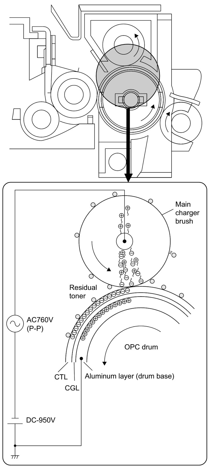
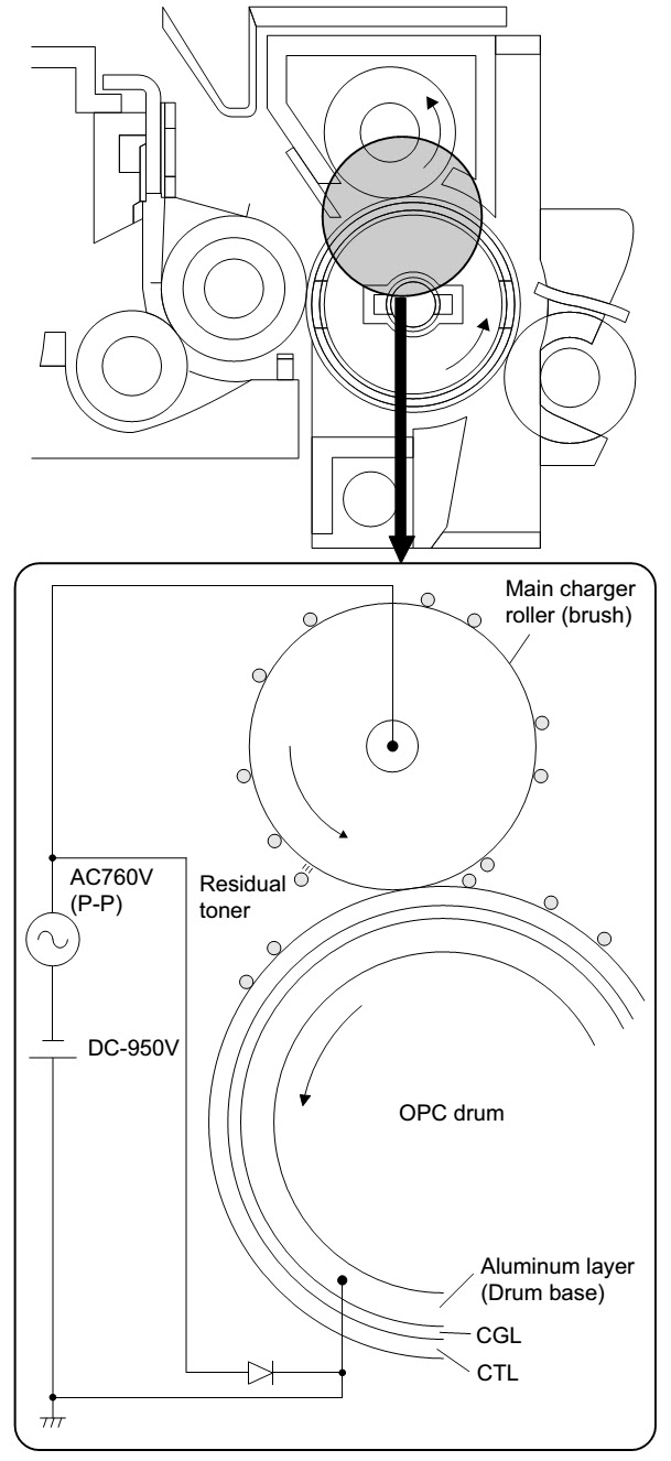
IMAGE FORMINGThe main charger is a rotating brush roller. The main charger removes residual toner from the OPC drum by its rotating sweeping action and causes it to stick to the brush. At the same time, a high voltage of -950V is applied to the main charger roller to generate a discharge of electricity between the roller and the OPC drum, generating positive and negative charges. The negative charges are attracted to the OPC drum, and evenly distributed on the OPC drum. (The OPC drum surface is evenly charged.)
![]()
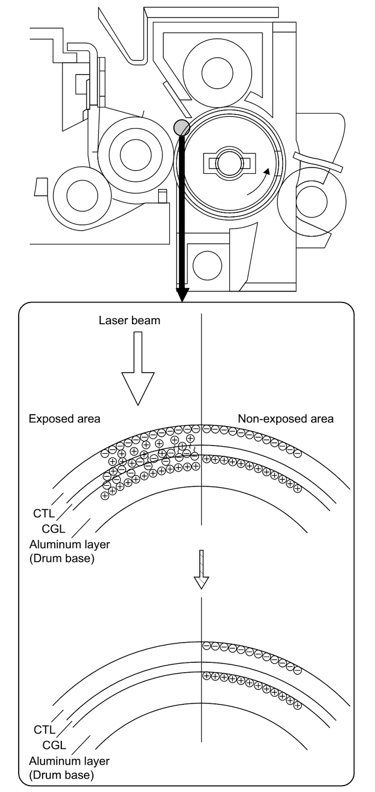
Laser beam scanning light corresponding to the print data is radiated on the OPC drum. Positive and negative charges are generated in the OPC drum CGL exposed with the laser beam. Positive charges generated in the CGL are attracted toward the OPC drum surface (negative charges), and negative charges toward the aluminium layer (positive charges). Therefore, the positive and negative charges neutralize each other in the laser-exposed area of the OPC drum surface and the aluminium layer, decreasing the potential of the OPC drum surface. The area, which is not exposed to laser beam, has no change, and the OPC drum surface remains negatively charged to keep a high potential. As a result, latent electrostatic images are formed on the OPC drum.
CLICK ON PICTURES TO ZOOM
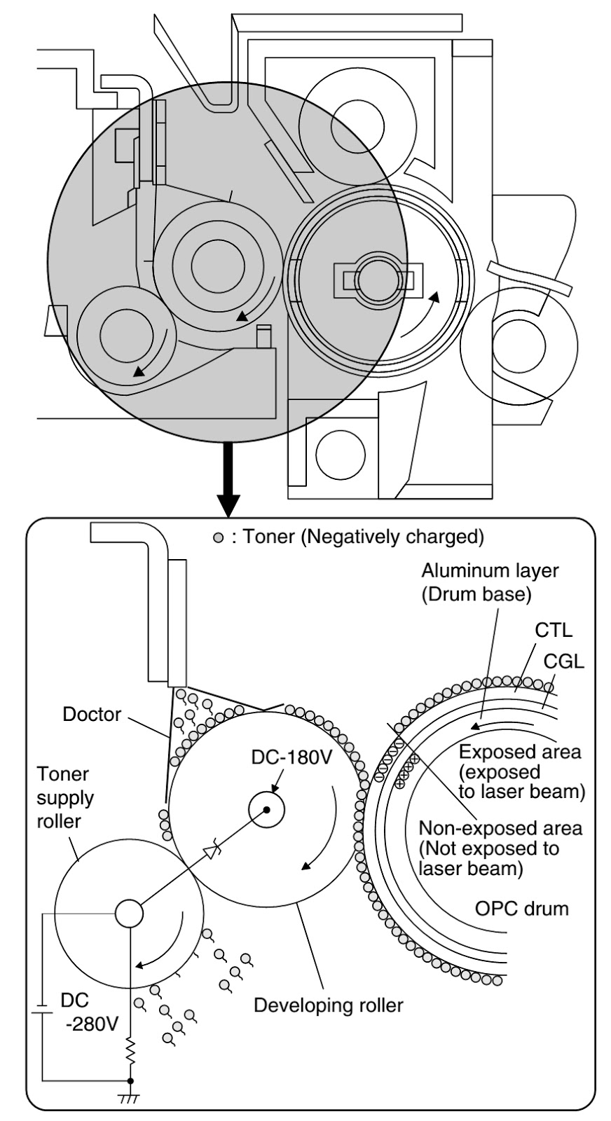
Development
Toner is attached to the latent electrostatic images on the OPC drum to form visible images. Toner is transported to the scraper area by the toner supply roller and the developing roller. The scraper controls the quantity of toner to be transported to the doctor section. Toner transported to the doctor section is then passed between the developing roller and the doctor to form a thin toner layer on the developing roller by the pressure applied by the doctor. When toner passes between the developing roller and the doctor, it is charged negatively by friction. When an area of OPC drum, which was exposed, to laser beam and lost its charge comes in contact with the developing roller, toner moves from the developing roller to the OPC drum surface. The principle of toner movement from the developing roller to the OPC drum surface is as follows.
The bias voltage of DC-280V is applied to the developing roller. Toner is charged negatively by the difference (electrical energy) between the bias voltage and the OPC drum surface potential and is attracted to the OPC drum surface which is positively charged. At that time, the potential of the area of the OPC drum, which was exposed to the laser beam and lost its charge, is higher than that of the developing roller.
On the other hand, when an area of OPC drum, which was not exposed to the laser beam and did not lose its charge comes in contact with the developing roller, any residual toner attached to the OPC drum is transferred to the developing roller which is more positively charged. As a result, the developing unit collects unnecessary toner on the OPC drum. The operating principle for that case is contrary to that for transfer of toner from the developing roller to the OPC drum surface. (The electric field energy direction is contrary.
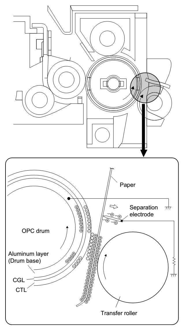
Visible images of toner on the OPC drum are transferred to the paper.
The high voltage of DC+3600V plus AC760V (P-P) is applied to the transfer roller to generate electric discharge between the roller and the OPC drum, generating positive and negative charges. Positive charges are attracted to the OPC drum and attached to the paper transported between the transfer roller and the OPC drum. Therefore the paper has a strong positive charge. Negatively charged toner on the OPC drum is attracted by the paper which is positively charged, and the visible images of toner are transferred onto the paper.
![]()
The paper is separated from the OPC drum. There is an electrostatic force between the paper, which is positively charged in transfer operation, and the OPC drum which is negatively charged. The positive charge on the paper is released to the separation electrode, which is the same potential as the aluminum layer of the OPC drum, to reduce the potential difference between the OPC drum and the paper, reducing the electrostatic force. This operation facilitates separation of the paper from the OPC drum.
The drum surface is discharged to facilitate cleaning of the drum surface. (The main charger roller easily collects the remaining toner.) The main charger is a rotating brush roller. The main charger removes residual toner from the OPC drum by its rotating sweeping action and causes it to stick to the brush. The main charger brush is in close contact with the mesh-type brush cleaning plate which removes toner and paper dust from the main charger brush mechanically.
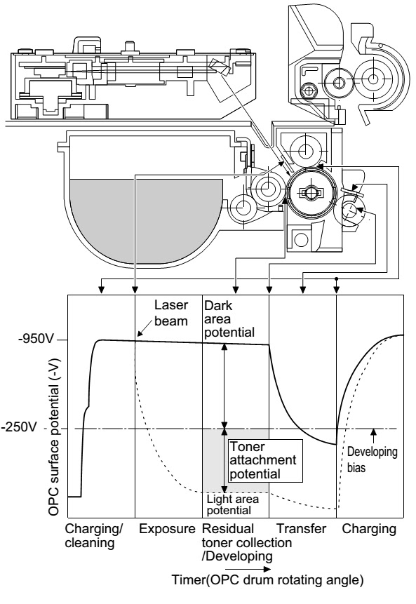
OPC drum surface potential
Transition of OPC drums surface potential by print operation.
OPC drum surface potential and developing bias voltage in development.