Quantcast
Channel: Electro help
Viewing all 2033 articles
Browse latest View live

HOW TO REMOVE / REPLACE BATTERY - SONY VAIO NOTEBOOK

$
0
0

BATTERY REPLACEMENT
You can use a battery pack as a source of power. The battery pack that comes with your notebook is not fully charged at the time of purchase. Follow the steps below to insert and charge the battery pack.
To Insert the Battery Pack
You can insert or remove the battery pack without turning off the notebook when your notebook is connected to the AC adapter. Before inserting or removing a battery pack, close the cover.

  • Move the lock lever on the bottom of the notebook to the UNLOCK position.
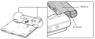
  • Align the grooves and tabs on the battery with the tabs and notches on the back of the notebook, and then slide the battery toward the notebook until it clicks into place.
INSERTING BATTERY PACK
Slide the lock lever into the LOCK position to secure the battery on the notebook.

The notebook automatically charges the battery (the battery indicator light flashes in a double-blink pattern as the battery charges). When the battery is 85% full, the battery indicator light turns off. This process takes 5.5 hours if the system is on. To charge the battery completely, continue charging for approximately 3 additional hours.
To Remove the Battery Pack
You can insert or remove the battery pack without turning off the notebook when your notebook is connected to the AC adapter. Before inserting or removing a battery pack, close the cover.
  • Turn off the notebook and close the cover.
  • Slide the lock lever to the UNLOCK position.
  • Slide the release lever to the UNLOCK position and slide the battery away from the notebook.

You may lose data if you remove the battery pack while the notebook is on and not connected to the AC adapter or if you remove the battery while the notebook is in a power saving mode.
  • If you find that an application exhibits unexpected behavior (such as reduced video quality) after returning from a power saving mode, you should close that application before your notebook enters a power saving mode.
  • For maximum audio and video performance, use Power Panel to select either the AC Power Profile or the Power Management Off profile.
  • If your battery level falls to less than 10 percent, you should either attach the AC adapter to recharge the battery or shut down your notebook and insert a fully charged battery.

When the internal backup battery is low on power, it may not be able to boot your system properly. You can correct this condition as follows:
  • Plug in the AC adapter and allow the notebook to charge for one hour while the power is on. Do not use the notebook during this time.
  • After one hour, turn the power off and then on again. To charge the internal backup battery fully, keep the AC adapter connected for more than 24 hours after turning the power on. You can use your notebook while charging the battery.

The operating system may become unstable if a lower power state such as Hibernate is initiated and then changed before the operating system completely enters the lower power state. To restore the notebook to its normal operating stability, close all open applications, and slide the power switch forward and hold it there for four seconds or more to completely shut down the notebook.


SHARP FACSIMILE UX385 – FO785 - NX575IT FAX MACHINE - SERVICE / DIAGNOSTIC MODE and SERVICE SOFT SWITCH

$
0
0

ENTERING THE DIAGNOSTIC MODE

                                            Press

FQH0  (UX-385DE)
FQI0 (FO-785DE)
FRB0  (UX-385GG)
FRC0  (UX-385IT)
FRD0  (FO-785IT/NX-575IT)
FQZ0 (UX-385ES)
FRA0 (FO-785ES)
FQY0 (UX-385H)
CLICK ON PICTURES TO ZOOM
If the diag mode cannot be set, repeat the diag mode operation, performing the following operation.
After the power is turned on and "WAIT A MOMENT" is indicated, press the STOP key.
In relation with the process response (request from Production Engineering) "WAIT A MOMENT" clock indication may appear depending on STOP key timing. If the STOP key is held down, "MEMORY CLEAR?" appears.
DIAGNOSTIC ITEMS
ITEM NO
DIRECT KEY [FO-785 / NX-575]

DIRECT KEY
UX-385
Contents
Function
1
1
1
SOFT SWITCH MODE
Soft switches are displayed and changed. List can be output

2
2
2
ROM & RAM CHECK
ROM is sum-checked, and RAM is matched. Result list is output.

3
3
3
AGING MODE
10 sheets of check patterns are output every 5 minutes per sheet.

4
4
4
PANEL KEY TEST
Panel keys are tested. Result list is output.

5
5
5
CHECK PATTERN
Check pattern is output.

6
6
 ==
SIGNAL SEND MODE
Various signals of FAX communication are output

7
7
 ==
MEMORY CLEAR
Back-up memory is cleared, and is set at delivery

8
8
 ==
SHADING MODE
Shading compensation is performed in this mode.

9
 ==
 ==
ALL BLACK PRINT
To check the print head, whole dots are printed over the interval of 2 m

10
 ==
 ==
AUTO FEEDER MODE
Insertion and discharge of document are tested.

11
 ==
 ==
MESSAGE PRINT
The display message of each language is printed out together with the English equivalent.
(DE/GG/IT/ES only)
ITEMS DESCRIPTION
Soft switch mode
Used to change the soft switch settings.
The soft switch which is stored internally is set by using the keys.
The available soft switches are SW-A1 to SW-N3.
The content of soft switches is shown in page 2-5 to 2-18.
The contents are set to factory default settings.
 ROM & RAM check
ROM executes the sum check, and RAM executes the matching test.
The result will be notified with the number of short sounds of the buzzer as well as by printing the ROM & RAM check list.  Number of short sounds of buzzer
0 àNo error
1àROM error
2 àRAM error (32Kbyte)
Aging mode
If any document is first present, copying will be executed sheet by sheet.
If no document is present, the check pattern will be printed sheet by sheet. This operation will be executed at a rate of one sheet per 5 minutes, and will be ended at a total of 10 sheets.
Panel key test
This mode is used to check whether each key operates properly or not.
Press the key on the operation panel, and the key will be displayed on the display. Therefore, press all keys. At this time, finally press the STOP key.  When the STOP key is pressed, the keys, which are not judged as “pressed”, will be printed on the result list.   LED part of the contact image sensor (CIS) is kept on during the term from when "START" of the panel test mode to end with the STOP key.
  • Check pattern
This mode is used to check the state of the printing head. It is ended with the following pattern printed on one printing sheet.
  1. Longitudinal stripe 2 Approx. 30 mm.  2 Black dots and 2 white dots are repeatedly progressed on one line.
  2. Full black Approx. 30 mm.
Signal send mode
This mode is used to send various signals to the circuit during FAX communication. Every push of START key sends a signal in the following sequence. Moreover, the signal sound is also output to the speaker when the line monitor of the soft switch is on.
  1. No signals
  2. 14400BPS (V.33)
  3. 12000BPS (V.33)
  4. 14400BPS (V.17)
  5. 12000BPS (V.17)
  6. 9600BPS (V.17)
  7. 7200BPS (V.17)
  8. 9600BPS (V.29)
  9. 7200BPS (V.29)
  10. 4800BPS (V27ter)
  11. 2400BPS (V27ter)
  12. 300BPS (FLAG)
  13. 2100Hz (CED)
  14. 1100Hz (CNG)
  15. PSEUDO RINGER
Memory clear
This mode is used to clear the backup memory and reset to the default settings.
Shading mode
The mode is used for the shooting compensation. For reading, set up the special original paper.  The shooting compensation memorizes the reference data of white and black for reading.  Moreover, the memorized data is not erased even if memory clear mode is executed.
All black print
This mode is used to check the state of the printing head and intentionally overheat it. Whole dots are printed over the interval of 2 m. If it is overheated or the printing sheet is jammed, press STOP key for the end.
Auto feeder mode
In this mode, a document is inserted and discharged to check the auto feed function.  After this mode is started, set a document, and the document feed will be automatically tested.
Message print (DE/GG/IT/ES only)
In this mode, all the message data, which are used for displaying indication and list print, are printed as a contrast table of the selected language and English.

SHARP FACSMILE UX-370H/310H/FO-730H - MECHANISM BLOCKS - DESCRIPTION

$
0
0


MECHANISM
Document feed block
Document feed operation
  • The original, which is set in the document hopper, feeds automatically when the front sensor is activated. This in turn activates the pulse motor which drives the document supply roller. The document stops when the lead edge is detected by the document sensor.
  • The lead edge of the original is fed a specified number of pulses after the lead edge of the document is detected for the reading process to begin.
  • The trailing edge of the original is fed a specific number of pulses after the trailing edge of the document deactivates the document sensor. The read process then stops and the original is discharged.
  • When the front sensor is in the OFF state (any document is not set up in the hopper guide), the drive will be stopped when the document is discharged.
Hopper mechanism

The hopper section contains document guides that are used to adjust the hopper to the width of the original document. This ensures that the
original feeds straight into the fax machine for scanning.
Document width: 148 mm to 216 mm (A5 longitudinal size to Letter longitudinal size)
NOTE: Adjust the document guide after setting up the document.
Automatic document feed
  • Use of the paper feed roller and separation rubber plate ensures error-free transport and separation of documents. The plate spring presses the document to the paper feed roller to assure smooth feeding of the document.
  • Document separation method: Separation rubber plate.

NOTE: Double-side coated documents and documents on facsimile recording paper should be inserted manually. The document feed quantity may be changed according to the document thickness.
Documents corresponding to a paper weight heavier than 64.3kg (74.3g/m2) and lighter than 135kg (157g/m2 ) are acceptable for manual feed.
Documents heavier than 135kg in terms of the paper weight must be duplicated on a copier to make it operative in the facsimile.
Loading the documents
  • Make sure that the documents are of suitable size and thickness, and free from creases, folds, curls, wet glue, wet ink, clips, staples and pins.
  • Place documents face down in the hopper.
  • Adjust the document guides to the document size.
  • Align the top edge of documents and gently place them into the hopper. The first page under the stack will be taken up by the feed roller to get ready for transmission.

NOTES:
Curled edge of documents, if any, must be straighten out.
Do not load the documents of different sizes and/or thickness together.
  • Documents requiring use of document carrier
  • Documents smaller than B6 (128mm x 182mm).
  • Documents thinner than the thickness of 0.06mm.
  • Documents containing creases, folds, or curls, especially those whose surface is curled (maximum allowable curl is 5mm).
  • Documents containing tears.
  • Carbon-backed documents. (Insert a white sheet of paper between the carbon back and the document carrier to avoid transfer of carbon to the carrier.)
  • Documents containing an easily separable writing material (e.g., those written with a lead pencil).
  • Transparent documents.
  • Folded or glued documents.  Document in document carrier should be inserted manually into the feeder.
Recording block

Driving
In the drive mechanism, the rotating force of the pulse motor for both transmission and reception is transmitted to the paper supply roller, the recording paper feed roller and imaging film drive gear through the pulse motor axle gear, reduction gear and planetary gear.
Recording
This equipment employs the thermal transcription system, which used the thermal head imaging film.
Thermal head:  The thermal head is composed of 2,016 heating elements in traverse line, and the resolution power is 8 dots/mm. The maximum speed is 10ms/line.
Structure of recording mechanism
Recording is achieved by applying a suitable pressure to the thermal head through the imaging film of the recording paper feed roller and the recording paper.  The main scanning is electronically done, and the sub-scanning is mechanically done (by sending the recording paper with the recording paper feed roller).
Recording paper transfer sequence
The recording paper stored in the RP hopper is fed with the PU roller, and the recording paper is stopped when the P-IN sensor is turned on by sensing its lead edge.
Hereafter, the imaging film and recording paper are transferred with the recording paper feed roller, and thermal transcription is done on the recording paper.
After thermal transcription, the imaging film is taken up by the roller on the take-up side, and the recording paper is discharged by the PO roller.  As basic, the density unevenness mainly results from the longitudinal misalignment of the thermal head to the heater line. Otherwise, the head is in uneven contact with the recording paper feed roller, or the imaging film is wrinkled.
The following items are described as the simplified checking method.
  • Is the power and signal cables of the thermal head suitably treated?
  • Does the same symptom appear even if the thermal head pres-sure spring is replaced?
  • Is the feed roller of the recording paper concentric? (Density is uneven at intervals.)
  • Does the same symptom appear even if the thermal head is replaced?
  • Is the imaging film stained or wrinkled?


HOW TO DISASSEMBLE SHARP UX-370H / 310H / FO-730H - FAX MACHINE

$
0
0


DISASSEMBLE PROCEDURE [PWB’s, drive unit, AC cord ass’y and speaker]
Paper roller etc. and sensor lever
CLICK ON PICTURES TO ZOOM
Drive frame
Sub frame unit, original paper guide, operation panel unit and CIS unit.
Upper cabinet and document guide upper unit
Document guide upper
Sub frame, top cover unit RP hopper unit
Top cover and RP hopper
Thermal head
Wire treatment

SHARP Fax-Machnine - UX-385DE/H/GG/IT/ES _ FO-785DE/IT/ES/NX-575IT - MAIN POWER SMPS SCHEMATIC [Circuit Diagram]

$
0
0

POWER SUPPLY SCHEMATIC {Voltage Outputs}
PCB
CLICK ON PICTURES TO ZOOM

GE27GT630 - HOW TO ENTER SERVICE MODE - ADJUSTMENTS - ERROR CODES

$
0
0

TO ENTER SERVICE MODE
The following adjustment procedures are accessed by a service menu.
  • To access the service menu, turn the receiver on, press the menu button and hold it down while pressing the power button.
  • While holding down the menu button, release the power button and press the volume + button.
  • The screen will display a one line menu, on the left the parameter P0, and on the right the value of that parameter V0. Release buttons. Selecting the proper parameter and changing the value of that parameter make adjustments.
  • To change the parameter number use channel up and down buttons.
  • To adjust the current value of that parameter use volume +and - buttons.
  • To access and change any of the adjustments, the proper parameter pass number must be entered.  
  • When these parameters are modified, the T-Chip and the corresponding EEPROM are updated. All service adjustments are bus controlled, except focus and screen.
NOTE: In order to adjust the RF AGC, audio or video levels, tuner, PIP, or stereo circuits, the Chipper Check hardware and software must be used. This can be purchased from Thomson Electronics. Before making any changes to any of the values, record the On Set values.
ADJUSTMENT PARAMETERS
ERROR CODES
  • If certain failures occur, the matching error codes will be stored in the EEPROM. These error codes will be displayed in parameters 1, 2, and 3. 
  • The first failure error code will be stored at parameter 1 and the second failure error code will be stored at parameter 2. 
  • Parameter 3 will be updated to display the most recent failure occurred in the chassis. If a failure of a bus IC occurred, the normal acknowledgment checking of that bus will be disabled in the service mode and the address of that IC which failed will be stored in one of the error code parameters. 
  • After every repair is done to the chassis it is recommended to check the error code parameters, and reset them back to value 0.
CLICK ON TABLES TO ZOOM

POWER SUPPLY CIRCUIT DIAGRAM [Schematic] - GE 27GT 630TX 51 - 27" TV

$
0
0


MAIN POWER REGULATOR SCHEMATIC

CLICK ON SCHEMATIC TO ZOOM

PHILIPS MAGNAVOX - HOW TO ADJUST WHITE BALANCE - How to Upgrade Software - 26MD251 – 32MD251 – 37MD321 – 37MF331 – 42MF231 – 42MF521 – 42MF531

$
0
0


WHITE BALANCE ADJUSTMENT
In case the white-balance data memory IC or main EEPROM which storage all factory settings were replaced due to a defect, the data have to be re-adjust It is advised to re-soldered DDC IC and main EEPROM from the old board onto the new board if circuit board have been replaced, in this case the white-balance data does not need to be re-adjust.
Adjustment process
  • Press the “062596” and INFO key(Red key) with IR Remoter in TV mode, there is a warning OSD displayed.
  • In the Factory menu, select “Alignments à White point”
  • There are “Color temperature”, “White point red”, “White point green”, “White point blue”, “Red BL  offset” and “Green BL offset” items which can be adjusted.
  • After adjust the items, go back to the factory main menu, press DOWN to next page, and select “Store”, press “OK” key, then the OSD will show “store completed”
  • Reboot the TV set.  The white balance setting is changed.
Typical white balance value
Software Upgrade Procedure
File fort the main application software upgrade
  • The UPG file which you want to be upgraded should be copied to the folder “upgrades” in the root of USB, the file which is named as “  ”hja5usecotpv_dev_RXX.upg” [the XX of the filename is the version of the software] and the file size is about 9875K.
Upgrade the main application software in normal mode
  • Push the USB in the USB interface of the PDP TV set.
  • The PDP TV set is in power on mode [normal mode]
  • Enter the user menu, select “Installation àsoftware upgrade àlocal upgrades/application” with IR remote control, the application will check the software from USB automatically.
  • Select the file you want to update to the TV set and use INFO key with IR Remoter to do “Upgrade now.
  • If the software version you selected is equal or older than current one, the OSD for confirmation will be displayed, choose YES (FORMAT key) to upgrade and No (key) to cancel the upgrade; else the software will be upgraded automatically.
  • When the upgrade is finished automatically, reboot the set.


HOW TO DISASSEMBLE PHILIPS MAGNAVOX Plasma TV - 26MD251 – 32MD251 – 37MD321 – 37MF331 – 42MF231 – 42MF521 – 42MF531 - Universal Remote control Set-up codes

$
0
0


STAND DISASSEMBLE
PDP INTERNAL VIEW
BACK COVER REMOVAL
  • Remove the six big black colored screws in the panel holder as the red-circle showed (1).
  • Remove the seven black colored screws around the terminals as the green-pane showed (2).
  • Remove the Sixteen black colored screws around the back cover as the blue-pane showed (3)

  • Carefully prize up the back cover from the left of the PDP (5)
Beyond this is not recommended, if you are not qualified and inexperienced in Plasma TV servicing.
Universal Remote Control Set-up Code list
0020 0037 0054 0024 0556 0028 0030 0036 0179 0186 0187 0386 0706 0780 1454
017,021,022,075,081,082, 087,088,089,090,101,102,143,144,145,146,147,196,197

HOW TO REMOVE REAR LOW COVER - PDC BOARD - PANEL[PIXEL] DEFECTS - PHILIPS MAGNAVOX PLASMA - Disassembly - 26MD251 – 32MD251 – 37MD321 – 37MF331 – 42MF231 – 42MF521 – 42MF531

$
0
0


REAR LOW COVER REMOVAL
Remove the three black screws in rear low cover.
Remove the six black screws.
PDC [Power Down Control] board removal.
[1]  Remove the four silver screws (1) remove the panel stand from the panel holder as in the arrowed direction.
[2]  Remove the four silver flat screws (2).
[3]  Remove the two black screws (3).
[4]  Remove the two silver screws (4).
[5]  Remove the panel holder from PDP.
[6]  Disconnect CN901 & CN903 from PDC board.
[7]  Remove the four silver screws (5) and remove the PDC board.
PANEL MODULE REMOVAL
[1]  Remove the 8 silver flat screws around the two panel holder (1).
[2]  Remove all aluminum foil around panel (2), after assemble the new panel, must re-fix the aluminum foil , if it is broken, change a new one, otherwise the EMI can be affected.

[3]  Remove the four silver screw around the panel corner (3).
940  Tow people must hold the panel holder 1 and 2 respectively, and then uplift the panel module and move it out from the front cover [Bezel].
PANEL [INTERNAL VIEW]
PANEL DEFECTS
A panel may have defective cells that cannot be controlled. These defective cells can be categorized into three types;
  • Non-lighting cell defect: defect in which the cell is always off
  • Non-extinguishing cell defect: defect in which the cell is always on.
  • Flickering cell defect: defect in which the cell is flickering.

Test Pattern: Full White, Full Red, Full Green and Full Blue with 1023 (10 Bit) gray level.
The display effect specifications define the allowed limits for display cell defects  are used as the criteria in determining whether a panel should be allowed.
Item
Number of cell defects
Distance between cell defects

Non-lighting cell defect
Zone A: 3 and less
Zone B: 8 and less


Non-extinguishing cell defect
Zone A: 0 
Zone B: 1 and less
Regardless of A and B zone, Distance between the cells is over 15mm

Total Defect
Total number of cell
defects in Zone A and B is 8 and less


Flickering cell defect
Zone A: 0 
Zone B: 1 and less


DEFINITION OF PIXEL DEFECTS
Defects of Glass Filter
But, the distance between defects must be over 30mm.
Both parties shall settle any defect without prescribed contents on the specifications on deliberation.

POWER - OFPC - POWER FILTER - SCHEMATIC [Circuit diagram] - PHILIPS MAGNAVOX PLASMA TV _ IRF 3710Z_UV 3843A

$
0
0


POWER FILTER SCHEMATIC
POWER FILTER PCB
MAIN POWER DOWN CONTROL; SCHEMATIC
MAIN POWER DOWN CONTROL PCB
OFPC; SCHEMATIC
OFPC PCB
CLICK ON PICTURES TO ZOOM

PANASONIC CF-18 NOTEBOOK COMPUTER [TOUGHBOOK] - TROUBLESHOOTING - ERROR CODES

$
0
0

DIAGNOSIS PROCEDURE
Flowchart
The set has a boot check function called POST (Power-On Self Test) in it. The condition of the main body is diagnosed by checking beep sound or error code.
  • Start  à Test begins automatically when power switch is set to ON.
  • Normal finish .....After memory checking, a beep sound is issued once and the set is placed into automatic stop.
Note: If no error occurs, nothing is displayed. (No display of OK, etc.)
Error Diagnosis by Checking Beep Signal Sound The beep sound is as follows:
Power-On Self Test (Boot Check)
Diagnosis
Beep signal sound
Error message


1(long sound)-2
BIOS ROM error


1-2-2-3
BIOS ROM error


1-3-1-1
RAM error

Main Board
1-3-1-3
Keyboard controller error


1-3-4-1
RAM error


1-3-4-3
RAM error


1-4-1-1
RAM error


2-1-2-3
BIOS ROM error


2-2-3-1
Occurrence of unexpected offering
A beep sound is also issued in case of other I/O trouble.


ERROR CODE LIST
   The following is a list of the messages that BIOS can display. Most of them occur during POST. Some of them display information about a hardware device, e.g., the amount of memory installed. Others may indicate a problem with a device, such as the way it has been configured.
   Following the list are explanations of the messages and remedies for reported problems.  If your system displays one of except the messages marked below with an asterisk (*), write down the message and contact Panasonic Technical Support. If your system fails after you make changes in the Set-up menus, reset the computer, enter Set-up and install Set-up defaults or correct the error.
0200 Failure Fixed Disk.  Fixed disk in not working or not configured properly. Check to see if fixed disk is attached properly. Run Setup. Find out if the fixed-disk type is correctly identified.
0210 Stuck key.  Stuck key on keyboard.
0211 Keyboard error.  Keyboard not working.
0212 Keyboard Controller Failed.  Keyboard controller failed test. May require replacing keyboard controller.
0213 Keyboard locked - Unlock key switch.  Unlock the system to proceed.
0230 System RAM Failed at offset : nnnn
System RAM failed at offset nnnnof in the 64k block at which the error was detected.
0231 Shadow RAM Failed at offset : nnnn
Shadow RAM failed at offset nnnnof the 64k block at which the error was detected.
0232 Extended RAM Failed at offset : nnnn.  Extended memory not working or not configured properly at offset nnnn.
0250 System battery is dead - Replace and run SETUP.  The CMOS clock battery indicator shows the battery is dead. Replace the battery and run Setup to reconfigure the system.
*0251 System CMOS checksum bad - Default configuration used.  System CMOS has been corrupted or modified incorrectly, perhaps by an application program that changes data stored in CMOS. The BIOS installed Default SETUP Values. If you do not want these values, enter Setup and enter your own values. If the error persists, check the system battery or contact Panasonic Technical Support.
0260 System timer error.  The timer test failed. Requires repair of system board.
0270 Real time clock error.  Real-time clock fails BIOS test. May require board repair.
*0280 Previous boot incomplete - Default configuration used.  Previous POST did not complete successfully. A POST load default values and offers to run Setup. If the failure was caused by incorrect values and they are not corrected, the next boot will likely fail. On systems with control of wait states, improper Setup settings can also terminate POST and cause this error on the next boot. Run Setup and verify that the wait-state.  Configuration is correct. This error is cleared the next time the system is booted.
0281 Memory Size found by POST differed from EISA CMOS.  Memory size found by POST differed from EISA CMOS.
02D0 System cache error - Cache disabled.  Contact Panasonic Technical Support.
02F0: CPU ID: CPU socket number for Multi-Processor error.
02F4: EISA CMOS not writable.  ServerBIOS2 test error: Cannot write to EISA CMOS.
02F5: DMA Test Failed.  ServerBIOS2 test error: Cannot write to extended DMA (Direct Memory Access) registers.
02F6: Software NMI Failed.  ServerBIOS2 test error: Cannot generate software NMI (Non-Maskable Interrupt).
02F7: Fail - Safe Timer NMI Failed.  ServerBIOS2 test error: Fail-Safe Timer takes too long.
deviceaddress Conflict.  Address conflict for specified device.
Allocation Error for: device.  Run ISA or EISA Configuration Utility to resolve resource conflict for the specified device.
Failing Bits : nnnn.  The hex number nnnn is a map of the bits at the RAM address which failed the memory test.  Each 1 (one) in the map indicates a failed bit. See error 230,231 or 232 for offset address of the failure in System, Extended or Shadow memory.  Invalid System Configuration Data. 
  • Problem with NVRAM (CMOS) data.
  • I/O device IRQ conflict
  • I/O device IRQ conflict error.
  • Operating System not found
  • Operating system cannot be located on either drive A: or drive C:. Enter Setup and see if fixed disk and drive A: are properly identified.
Parity Check 1 nnnn.  Parity error found in the system bus. BIOS attempts to locate the address and display it on the screen. If it cannot locate the address, it displays ????. Parity is a method for checking errors in binary data. A parity error indicates that some data has been corrupted.
Parity Check 2 nnnn.  Parity error found in the I/O bus. BIOS attempts to locate the address and display it on the screen. If it cannot locate the address, it displays ????.
Press <F1> to resume, <F2> to Setup.  Displayed after any recoverable error message. Press <F1> to start the boot process or <F2> to enter a Setup and change the settings. Write down and follow the information shown on the screen.
                              Click on Table to Zoom

HOW TO DISASSEMBLE - PANASONIC CF-18 NOTEBOOK COMPUTER

$
0
0
DISASSEMBLE PROCEDURE
Power off the computer. Do not shut down to the Suspend or Hibernation mode.
Do not add peripherals while the computer  in the Suspend or Hibernation mode; abnormal operation may result.
REMOVING THE BATTERY PACK & HARD DISC PACK
  • Open the Battery Cover.
  • Remove the Battery Pack.
  • Open the HDD Cover.
  • Remove the HDD Pack.
  • Remove the two Screws. [A]
  • Remove the HDD Case Aand the HDD Case B.
  • Remove the HDD.  Screw [A] : DFHE5025XA
REMOVING THE TOUCH PAD & KEYBOARD
  • Remove the Palm Rest Ass’y.
  • Remove the four Screws. [B]
  • Remove the KBD Plate.
  • Remove the Keyboard.
  • Remove the three Screws. [C]
  • Remove the KBD Connector Cover.
  • Disconnect the Cable from Connector (CN18).
  • Remove the TP Tape.
  • Disconnect the Cable from Connector (CN800).
  • Remove the Touch Pad and Click Button Plate. Screw [B]:DXSB2+5FZL [C]:DFHE5025XA
REMOVING SPEAKER
  • Remove the four Screws. [D]
  • Disconnect the Cable from Connector (CN37).
  • Remove the two Screws. [E]
  • Remove the Speaker Angle.  Screw [D]: DXQT2+D25FZL [E]: DXQT2+D3FZLT.
Click on pictures to Zoom
REMOVING THE REAR CABINET
  • Remove the thirteen Screws. [F]
  • Remove the Rear Cabinet.  Screw [F]: DXYN2+J8FZL

REMOVING DU LID UNIT
  • Remove the five Screws. [G]
  • Remove the DU Lid Angle and DU Lid.  Screw [G]: DXQT2+D3FZLT
REMOVING THE AUDIO PCB
Remove the two Screws. [H]
Disconnect the two Cables from two Connectors (CN701,CN702).
Remove the Audio PCB.  Screw [H]: DXSB2+5FZL
REMOVING THE WIRELESS MODULE, PORT PCB & MODEM PCB
  • Disconnect the two Antenna Cables from two Connectors (J5, J6).
  • Remove the Wireless Module.
  • Remove the three Screws. [I]
  • Remove the Port PCB.
  • Remove the Screw. [J]
  • Remove the Modem PCB.
  • Remove the two Screws. [K]
  • Remove the BAT CON angle.  Screw [I]: DXSB2+5FZL.  [J]: XSB2+4FNL. [K]: DXSB2+5FZL
REMOVING THE MAIN PCB
  • Disconnect the eight Cables from eight Connectors (CN3,CN9, CN12, CN14, CN23, CN30, CN35, CN36).
  • Remove the Screw. [L]
  • Remove the two Screws. [M]
  • Remove the four Screws. [N]
  • Remove the Main PCB.
  • Disconnect the two Cables from two Connectors (CN8,CN17).
  • Remove the PCMCIA Unit.  Screw [L]: DXSB2+5FZL. [M]: DXYN2+J12FNL. [N]: DXYN2+J18FNL
REMOVING PAD PCB & I/O PCB
  • Disconnect the Cable from Connector (CN801).
  • Remove the three Screws. [O]
  • Remove the PAD PCB.
  • Remove the four Screws. [P]
  • Remove the two Screws. [Q]
  • Remove the I/O PCB.  Screw [O]: DFHE5025XA.  [P]: DFHE5058ZA.  [Q]: DXSB2+5FZ

TX-W32D4DP - PANASONIC TV - POWER - HORIZONTAL OUT - VIDEO OUTPUT - SCHEMATIC DIAGRAM _ AN 8029[POWER CONTROL] – 2SK1365LB106[FET] – TDA6611Q [VIDEO OUTPUT] – ZTFM05001A [LOT]

$
0
0

POWER SUPPLY & HORIZONTAL OUTPUT
VIDEO OUTPUT SCHEMATIC
CLICK ON SCHEMATICS TO ZOOM

HOW TO UPDATE FIRMWARE TO TOSHIBA - 19AV500U - 26AV500U - 32AV500U - 37AV500U - 42AV500U

$
0
0
SOFTWARE UPDATE PROCEDURE
Required Tools:
  • Computer with available RS232 or USB port
  • 2008FWKT01 2008 Firmware Update Kit.
  • Update Firmware for Model (Note: Contact Toshiba Technical Support for Part Number   of the Update Firmware. The Firmware Update is NOT included with the 2008FWKT01 Kit)
  • Install the USB to Serial Adapter drivers. Instructions are on the CD driver disc included with the adapter. Attach the USB to Serial Adapter to the USB port of your computer.
  • Copy the contents of the supplied 2008FWKT01 Service Firmware Update Tool CD to a directory on your PC. Note the name and location of the directory for future reference.
  • Copy the firmware update file (file extension .ecc) for the model being serviced to the same directory location as in above step . Note the name and location of the directory for future reference.
  • To open the 2008FWKT01 “iDev” firmware update tool; use Windows Explorer locate the directory where you installed the CD files in step 2. Select the iDev directory and then click on the iDev.exe software Application.
  • Select “Setup” from the iDev application.
  • Select the Serial Port of which your USB to Serial Adapter is connected. (Note: when using the USB to Serial Adapter the Com ports are assigned by the operating system. Identify the correct COM port using your device manager in windows as reference. The USB to Serial
  • Adapter must be connected to identify the assigned port)
  • Set the Baud Rate to 115200.
  • Select the BROWSE (…) button to open the image file browser.
  • Select the “Firmware update” file (with file extension .ecc) for the TV receiver being updated. The Firmware update file will be in the directory where you placed the contents from step 3 in the Installation and Set-up procedure.
  • Select 'Open'.
  • Select 'OK'.
  • Select “down” to start the download process.
The Download image application will start and a message will indicate “Waiting for ping” Proceed to Section B “Upgrading the Firmware” procedure.
UPGRADING PROCEDURE
  • Remove AC power from the TV receiver
  • Connect the Serial Cable to the “Service Port” at the rear of the LCD TV receiver. Connect the Serial Cable to the USB to Serial Adapter between the Serial Cable and the PC USB port as shown below.
  • Apply AC power to the TV receiver. Confirm the TV receiver isin the “Off” state.
  • Confirm that steps of the “Installation and Setup of the iDev Software Tool and USB Drivers” were completed and the iDev software is “waiting for ping” as described above.
  • Turn on the TV receiver to begin the download as shown below. Do not remove AC power or interrupt the set during the download progress.
  • Upon completion of the firmware update a “Finished, Please reset the HDTV” banner will be displayed.
  • To reset, remove AC power to the TV receiver.
  • Reconnect AC power after the reset and confirm the firmware update by checking the version. (Enter Set-up Menu and select “System Status” to verify version.)
  • Firmware update is complete.  Perform any necessary service adjustment and safety procedures.
CLICK ON PICTURES TO ZOOM


TOSHIBA L4-CHASSIS LCD TVs - TROUBLESHOOTING TABLE -19AV500 .......42AV500

$
0
0

SET DEAD [NO SOUND - NO PICTURE]
NO OR DISTORTED VIDEO
BACK-LIGHT TROUBLESHOOTING
NO OR DISTORTED AUDIO
CLICK ON TABLES TO ZOOM

CHASSIS LAYOUT - TOSHIBA 26" AND 32" LCD TV - 26AV500_32AV500 - SERVICE MODE - PANEL CHANGE - URC Set-up Codes

$
0
0

26" CHASSIS LAYOUT
32" DISASSEMBLY
RUNNING PANEL CHANGE
CLICK ON PICTURES TO ZOOM
Service Mode
  • When in PC/Color stream HD 1,2 or Video-1, 2/Ant inputs, press the [Left àExit à Enter] of the remote control to enter factory mode.
  • During Factory Menu, if ‘Menu’ or ‘Exit’ key is pressed, system will Exit Factory mode.
  • Press ‘Up / Dn’ can move highlight item from Color Temperature à Timer clear à Preset Channel àNV clear à Full Power àSource calibration àReset to Default.
  • The Timer clear, NV clear & Reset Default items will have a check dialogue ‘Yes / No’ to do or not.
  • Push ‘Enter’ key can select high light item function.  Press ‘Left / right’ can adjust value.
  • Display panel Burn in Time on the bottom.
  • Display firmware version and released date on top.

Universal Remote Control Set-up codes.
0035 0060 0009 0154 0508 0036 0156 0070 0093 0243 0145 0102 0227 1508 0217 0264 0109 0381 0412 0718 0195 0191 0618 0644 1916 0650 1908 0821 0698 0037 1156 1256 1945 1656.

SERVICE MODE - TOSHIBA 29CJZ8UR TV - SELF DIAGNOSTIC FUNCTION

$
0
0
SERVICE MODE
  • Press [MUTE] button once on Remote Control.
  • Press [MUTE] button again to keep pressing.
  • While pressing the [MUTE] button, press MENU button on TV set.
  • Press MENU button on TV.
SERVICE MODE KEYS
  • Screen adjustment mode ON/OFF: -/-- button (on Remote)
  • Test signal selection : [POWER]button (on Remote)
  • Selection of the adjustment items : Channel ▲/▼ (on TV or Remote)
  • Change of the data value : Volume +/– (on TV or Remote)
  • Adjustment menu mode ON/OFF : MENU button (on TV)
  • Initialization of the memory (QA02) : CALL + Channel button on TV (▲)
  • Reset the count of operating protect circuit to “00”: CALL + Channel button on TV (▼)
“RCUT” selection : 1 button
“GCUT” selection : 2 button
“BCUT” selection : 3 button
“SCNT” selection : 4 button
“COLP” selection : 5 button --- Color thickness correction.  [Note: Displayed differently as shown below, depending on the setting of the receiving color system]
“TNTC” selection : 6 button
Convergence adj : YELLOW button
Self diagnostic display ON/OFF : 9 button.
TO SELECT AN ITEM TO ADJUST
Every pressing of CHANNEL ▲button in the service mode changes the adjustment items. ▼ (Button for reverse order).
TO ADJUST DATA VALUE
Pressing of VOLUME +/– button will change the value of data in the range from 00H to FFH. The variable range depends on the adjusting item.
TO EXIT SERVICE MODE
Pressing POWER button to turn off the TV once.
INITIALIZATION OF MEMORY DATA OF QA02
After replacing QA02, the following initialization is required.
  • Enter the service mode, then select any register item.
  • Press and hold the CALL button on the Remote, then press the CHANNEL▲ button on the TV. The initialization of QA02 has been complated.
  • Check the picture carefully. If necessary, adjust any adjustment item above.
  • Perform “Auto tune” on the owner’s manual.
CAUTION: Never attempt to initialize the data unless QA02 has been replaced.
SELF DIAGNOSTIC FUNCTION
  • Press “9” button on Remote Control during display of adjustment menu in the service mode.  The diagnosis will begin to check if interface among IC’s are executed properly.
During diagnosis, the following displays are shown.
  1. Firmware: Version information of microprocessor. In case of file name : JH9 and Version : 1.00 indicates[JH9_100].
  2. Time: Total hour of turn the TV on. (Unit : H)
  3. Power : Operation number of protecting circuit ----"00" is normal.  When indication is other than "00", over current apt to flow, and circuit parts may possibly be damaged.
  4. BusCont à"OK" is normal. When type name of semiconductor indicates.
  5. BLOCK. UV : TV reception mode.
     6.  Model name (7 digit)

Design mode - HOW TO ENTER DESIGN MODE - TOSHIBA 29CJZ8UR - Adjusting Items and Data Values - Service Mode Default Data Values

$
0
0
Design Mode
  • Select the Service mode {Visit previous post here for details}
  • While pressing CALL button on Remote and press MENU button on TV.
  • The following displays  are shown on the screen.


When QA02 is initialized, item “OPT3" of DESIGN MODE is set to the data of the representative model of this chassis family.  Therefore, because ON-SCREEN specification remains in the state of the representative of model. This model is required to reset the data of item “OPT3".
SELECTING THE ADJUSTING ITEMS
Every pressing of CHANNEL button in the design mode changes the adjustment items. (button for reverse order).
ADJUSTING THE DATA
Pressing of VOLUME / button will change the value of data.

ADJUSTING ITEMS AND DATA  IN THE DESIGN MODE:
SERVICE MODE DEFAULT DATA VALUES
CLICK ON CHARTS TO ZOOM

How to adjust Electrical Adjustments - Full Adjustments - TOSHIBA 29CJZ8UR - Vertical Height - Linearity - Horizontal Width Etc:-

$
0
0
Focus VR adjustment
  • Enter the service mode, then select any register item. {refer previous post here}
  • Press the TV/VIDEO button on the Remote until the black cross-bar pattern appears on the screen.
  • Adjust the FOCUS control (on T461) for well-defined scanning lines on the picture screen.
  • Select BRTC (brightness correction), and adjust the Vol – /+ button to reduce the value so that white portion of inside pattern slightly light.
  • Adjust Vol – /+ button to increase the data value of BRTC, and set it just before the difference between the belt of vertical retrace and the border of black portion of inside pattern is visible.  After that, return vertical height and contrast.
SUB-BRIGHTNESS (BRTC)
Note: Constrict the picture height until the vertical retrace line appears adjusting the item HIT (HEIGHT)
Set CONTRAST to minimum, and BRIGHTNESS to center by adjusting user controls.
Set the TV in service mode to get Black cross-bar of inside pattern.
HORIZONTAL POSITION ADJUSTMENT (HPOS)
Set the TV in service mode, and get black cross-bar signal with VIDEO button on remote hand unit.
VERTICAL POSITION ADJUSTMENT (VPOS)
Select either HPOS (Horizontal picture phase) or VPOS (Vertical picture phase) with CHANNEL / buttons, and adjust horizontal or vertical picture position in the center of screen with VOLUME – /+ buttons.
VERTICAL AMPLITUDE ADJUSTMENT (HIT) / {Height Adjustment}
  • Set the TV in service mode, and get black cross-hatch signal with VIDEO button on remote hand unit.
  • Select HIT (Vertical amplitude) with CHANNEL/ buttons, and adjust vertical amplitude with VOLUME – /+ buttons so that vertical amplitude lacks a little.
  • Adjust vertical amplitude with VOLUME – /+ buttons so that the first bar on cross-hatch signal touches edge of screen.
WIDTH (WID)
  • Call up the adjustment mode display, then select the item WID.
  • Press the Vol – /+ button to get the picture so the left and right edges of raster begins to lack.
  • Press the Vol – /+ button to advance the data by 7 steps. [Note : Check the horizontal picture position is correct.]
  • Call up the adjustment mode display, then select the item PARA.
  • Press the  STBY button on Remote until the cross-hatch pattern appears on the screen.
  • Press the Vol – /+ button to make vertical lines straight as shown below.
E-W PARABOLA (PARA).
WHITE BALANCE ADJUSTMENT
CUTOFF ADJUSTMENT
(RCUT)
(GCUT)
(BCUT)
DRIVE ADJUSTMENT
(GDRV)
(BDRV)
  • Set Contrast to 40, and brightness to +20 by picture control.
  • Receive the Black and White pattern.
  • Select RCUT, GCUT and BCUT with CHANNEL / buttons, to set individual values to Initial reference data, and to set GDRV and BDRV to Initial reference data with VOLUME– /+ buttons.
  • Press [-/- -] button on the remote control and rotate Screen VR to get one slight horizontal line on screen. {Note: Every pressing of [-/- -]button provides Horizontal line picture and Normal picture alternately.}
  • Press [-/- -] button to release horizontal line picture, and select the two other colors which did not light in the above step with CHANNEL /buttons. Then tap VOLUME– /+ buttons so that three colors slightly light in the same level
*  To correct white balance in light area, select GDRV and BDRV with CHANNEL ▲/▼ buttons to adjust.
*  To correct white balance in dark area, perform fine adjustment ofRCUT, GCUTandBCUT.

Cutoff adjustment and white balance adjustment.
RCUT
GCUT
BCUT
GDRV
BDRV
[Screen VR]
Setting to horizontal alignment, turn the screen VR to stop where the brightness lines are slightly luminous.  (Adjustment shall be made so that they look almost white.)
Cancel horizontal alignment.
Varying R, G and B CUTOFF, make white balance adjustment in the dark area.
Adjusting G and B DRIVE, make white balance adjustment in the bright area.
Repeat procedures 3 and 4 if necessary.
Total white signal Varying the level of input signal, adjust the brightness.
  • Turn the static VR knob to the “MIN.” position and the dynamic VR knob to the “MAX.” position.
  • Adjust the static VR knob to the “MAX.” direction to optimize the peripheral focus.
  • Adjust the dynamic VR knob to “MIN.” direction to optimize the center focus.
  • Adjust the static VR knob and the dynamic VR knob alternately to optimize the full screen focus.
Adjustable value:
Bright area: 11500K+0.0075uV(103cd/m2)
Dark area: 10500K+0.0105uV(17cd/m2)
{ No outside lighting shall be allowed.  Measurement shall be performed at the center of CRT.  Receiver shall be in the standard state.}
Sub contrast adjustment (SCNT)
Select SCNT in the sub data adjustment mode.
With TP-Y, set the amplitude from pedestal level to white peak to 0.70±0.03 V (0-p) [J-2ch sub brightness signal DYNAMIC].
Sub brightness adjustment (BRTC)
Select BRTC in the sub data adjustment mode.  Adjust the number of black solid lines to 4±1.5. [J-2ch sub brightness signal DYNAMIC].
DW sub screen contrast adjustment (PCNT)
Select PCNT in the sub data adjustment mode.
With TP-Y, make adjustment so that the amplitude of sub screen (right image) coincides with that of main screen (left image).
{J-2ch for both main and sub screens Sub brightness signal DYNAMIC}
Focus Adjustment (1)
Static (main): T461
Dynamic : T461
Conditions :
PAL RETMA ch
Screen Size : Wide
Presentation Mode : Dynamic.
Only for 34-inch model
Adjustment Procedure:
Only for 29-inch model
Adjust the Main Focus VR knob of T461 model to optimize centre focus.
Horizontal
For PAL/100 Hz/WIDE
Horizontal amplitude (WID)
Side pin distortion (PARA)
Trapezoidal distortion (TRAP)
Corner distortion (CNR)
Upper corner distortion (TCNR)
Lower corner distortion (BCNR)
CENT distortion (CPAR)
Parallelogram distortion (CSAW)
Horizontal phase (HPOS
Note POW/DEF board:
P451/M450 Horizontal screen positional switch.
Screen position shall be switched by inserting a plug into the above said pin (CENT should take the first stage)
{NTSC adjustment shall be made after PAL adjustment.}
  • With domestic 13ch, WIDE mode and DYNAMIC, adjust the right and left bars to the fifth center for horizontal phase (NHPO) and horizontal amplitude (NWID).
  • With domestic 11ch, NPAR, NTRA, NCNR and NCPAR (or NTCNR, NBCNR or NCSAW if necessary), adjust the screen distortion.
  • If necessary, make horizontal amplitude adjustment again.
Vertical
For PAL WIDE Vertical amplitude (HIT)
Vertical screen position (TCNR)
Vertical linearity (VLIN)
With vertical linearity (VLIN), control the upper and lower balances to be optimal.
With E-12ch, WIDE mode, DYNAMIC and 100 Hz, adjust the vertical screen position (VPOS) and amplitude (HIT) as shown in the following figure:
For NTSC WIDE
Vertical amplitude (NHIT)
For NTSC WIDE
Vertical amplitude (NHIT)
Vertical screen position (NVPO)
With domestic 13ch, WIDE mode and DYNAMIC, adjust the vertical screen position (NVPO) and amplitude (NHIT) as shown in the following figure:
NTSC adjustment shall be made after the PAL adjustment.

Viewing all 2033 articles
Browse latest View live


<script src="https://jsc.adskeeper.com/r/s/rssing.com.1596347.js" async> </script>