↧
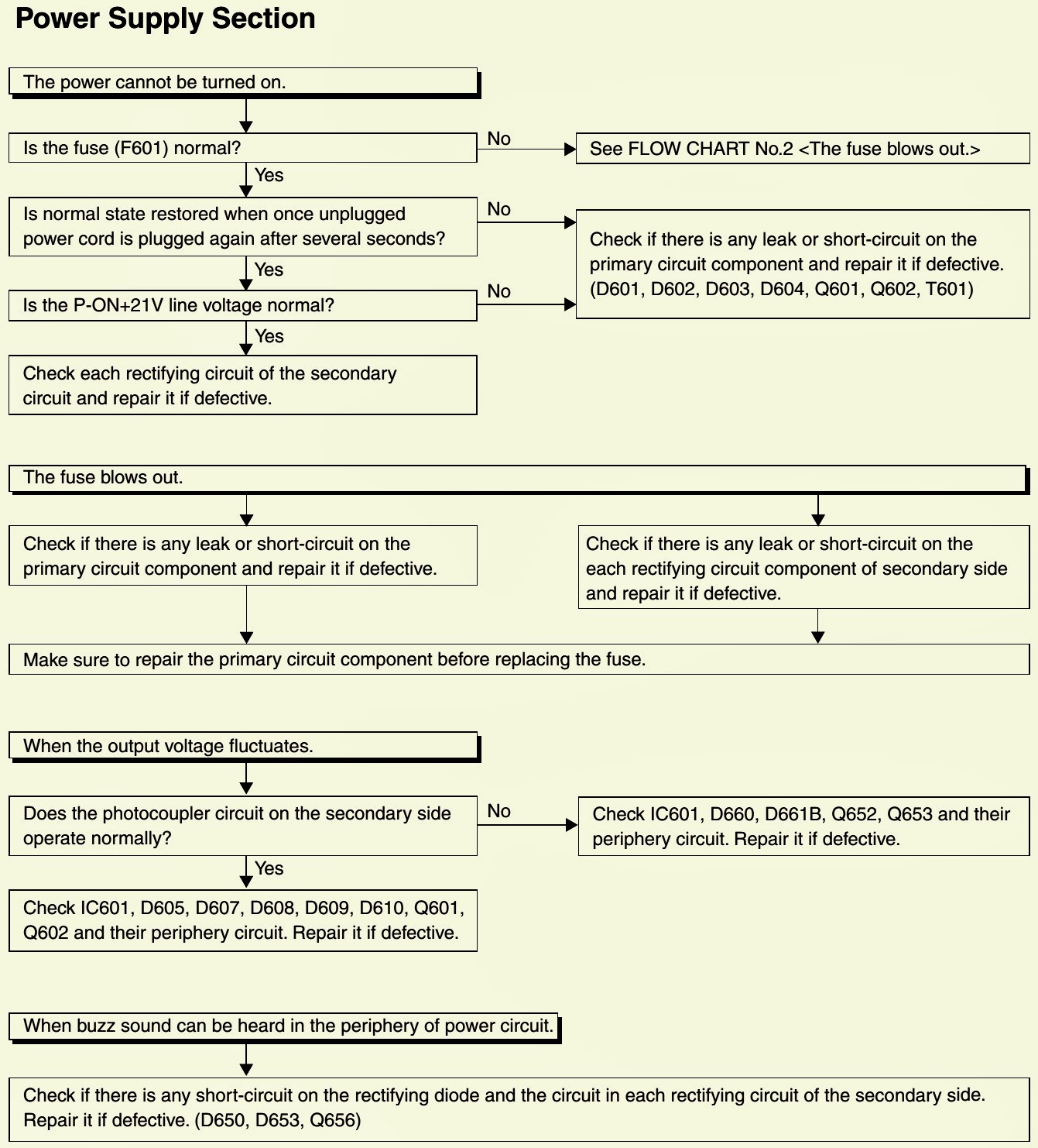
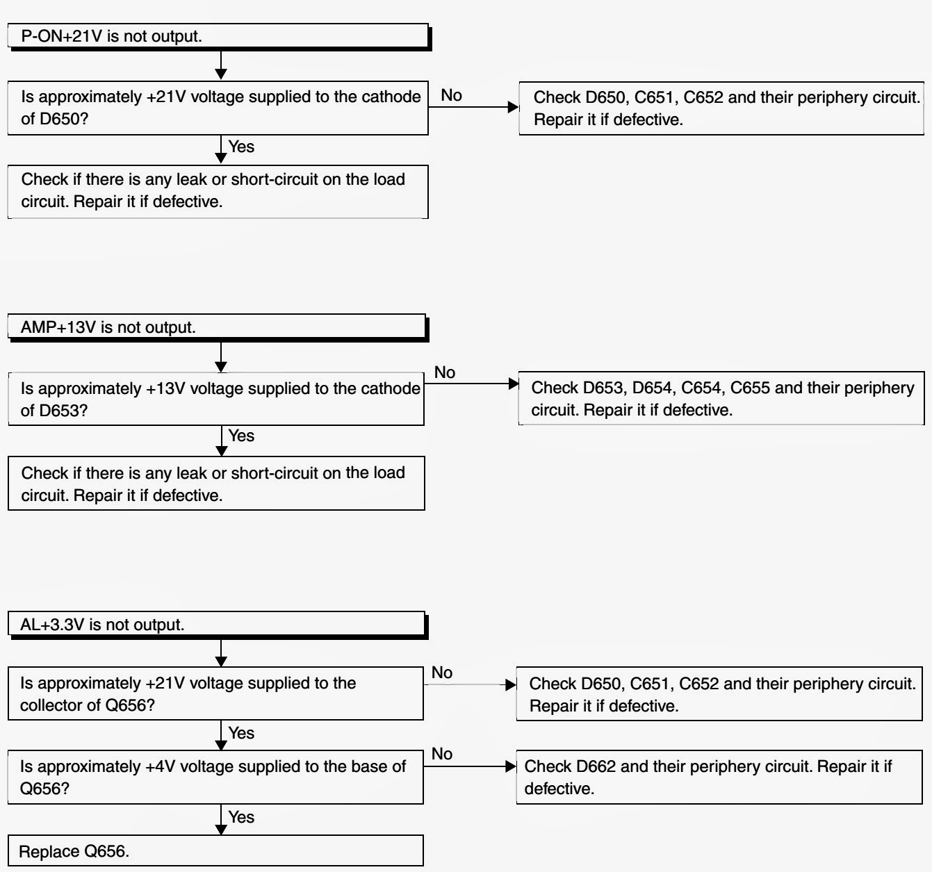
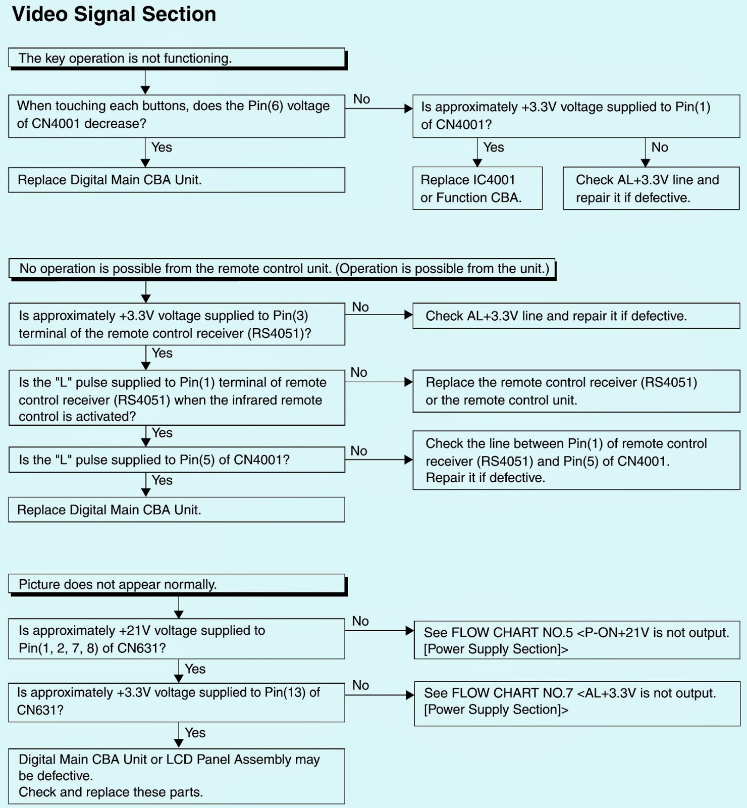
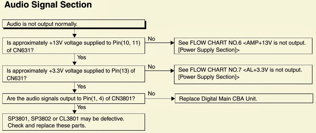
HOW TO TROUBLESHOOT - PHILIPS 22PFL 4507 - 22" LCD TV
↧
SOFTWARE UPGRADE PROCEDURE - PHILIPS 22PFL4507 - LCD TV - FACTORY UPGRADE
FACTORY UPGRADE (Firmware Upgrade/Flash Upgrade)
Firmware Upgrade (Filename example: FACT_TVNB012_00_UF_XX91_AA.ecc)
Upgrade the firmware and initialize the setting values.
The User Upgrade and the Firmware Upgrade (Factory Upgrade) will be done by the same file. If you want to upgrade the firmware and initialize the setting values also, add “FACT_” at the beginning of the filename.
If you want to upgrade the firmware only and leave the setting values as they are, eliminate the “FACT_” from the file-name.
Flash Upgrade (Filename example: ALL_TVNB012_00_UF_XX91_AA.ecc)
Upgrade the firmware and initialize the setting values along with the factory default such as White Balance, etc.
Before the upgrade, you will need to make a note of all the factory default so you will be able to set it back on the TV after the initialization.
The Flash Upgrade will be done by it's unique file.
The User Upgrade/Firmware Upgrade (Factory Upgrade) file cannot be used for this upgrade.
Update procedure
1. Turn the power off.
2. Insert the USB storage device to the USB port as shown below.
3. Turn the power on.
4. The update will start and the following will appear in the screen.
Note: If the above screen isn't displayed, repeat from step 1.
The appearance shown in *1 is described as follows.
5. When the firmware update is completed, the following will appear in the screen.
Remove the USB storage device from the USB port.
Turn the power off and turn the power on again.
Service mode initial screen with a word “INITIALIZED” will appear in the screen. The color of the word “INITIALIZED” will change from red to green when initialization is completed.
↧
↧
JBL SUB 135S – CINEMA PROPACK-600 – AMP-SUBWOOFER - SCHEMATIC (Circuit Diagram)
↧
FALCON 54 / 51 / 37TC6153 - TV - POWER SUPPLY SCHEMATIC - TDA16846 – SPA04N60C2[FET] – KA7632
↧
PANASONIC CR-14 - AUDIO MECHANISM - OPERATION PROCEDURES - [CD CHANGER]
DESCRIPTION OF TRAYS OPEN/CLOSE & DISC EXCHANGE OPERATIONS
CLICK ON THE PICTURES TO ZOOM IN
- The loading motor turns in the clockwise direction and the rotation is transmitted via the belt, the pulley gear also turns clockwise.
- The relay gear turns counter clockwise.
- The change gear turns clockwise.
- The cam gear turns counter clockwise.
- The OC drive gear turns clockwise driven OC gear assy.
- Trigger slide assy releases tray lock lever.
- Movement of OC gear assy releases all trays. (The operation of trays closed is the opposite of that for opening trays. Discs exchange is done during closing operation)
TRAY SELECTION OPERATION
- The loading motor turns in the clockwise direction and the rotation is transmitted via the belt, the pulley gear also turns clockwise.
- The relay gear turns counter clockwise.
- The change gear turns clockwise.
- The cam gear turns counter clockwise.
- The UD drive gear turns counter clockwise engages UD cam L guide drives UD connection turns counter clockwise, UD cam R guide is driven to move UD base unit down. (The operation of the UD base unit up is the opposite of that for the UD base unit down.)
PLAY OPERATION
The loading motor turns in the clockwise direction and the rotation is transmitted via the belt, the pulley gear also turns clockwise.
The relay gear turns counter clockwise.
The change gear turns clockwise.
The cam gear turns counter clockwise.
Turn the TRV motor clockwise, the tray will load into play position until OPU at the center position.
↧
↧
HOW TO DISASSEMBLE - PANASONIC CR-14 - CD CHANGER MECHANISM
DISASSEMBLING TRAVERSE UNIT ASS'Y IN PLAY POSITION
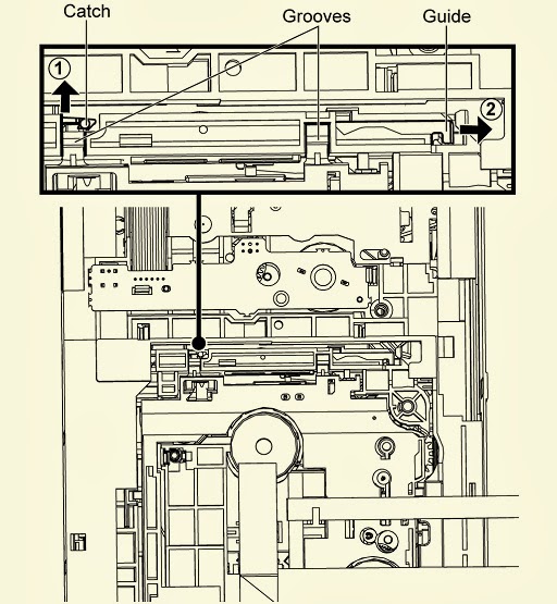
Release the catch and push the guide as arrows shown to open both grooves.
Detach the FFC wires from the adhesive areas. (Do not pull the FFC wire to remove the traverse unit assy, as it may cause damage to the slot)CLICK ON THE PICTURES TO ZOOM IN
Press down the traverse unit assy.
Remove the traverse unit assy as arrow shown.
↧
KONKA - K2166 – DT-21K2 – K3731H1 - POWER SUPPLY SCHEMATIC (Circuit Diagram) _ SERVICE MODE
APPLICABLE TO KONKA:
K2966EZ/SZ_K2178C_K2166SZ_K2199S_K2166CZ/EZ/SZ_K1618V_K1438C/D_K1439E/CZ/S_K1418C/D_K1478C_K3731H1_K1402_DT-14K2/K3/K4_DT-20K4_DT-21K2
SERVICE MODE
K2966EZ/SZ_K2178C_K2166SZ_K2199S_K2166CZ/EZ/SZ_K1618V_K1438C/D_K1439E/CZ/S_K1418C/D_K1478C_K3731H1_K1402_DT-14K2/K3/K4_DT-20K4_DT-21K2
SERVICE MODE
- Press FAC button on the factory remote control once, the screen will display FACTORY MODE menu, press MUTE button again to enter into sub-menu.
- Press [O] button to display a horizontal light line on the screen, and presses this button again to restore the screen.
- Press P+/P-buttons to select desired adjust item.
- Press V+/V-buttons to adjust selected item value.
- Automatic adjust, green color shows adjustment is OK when automatic adjust ended.
- Press FAC button again to exit FACTORY MODE.
POWER SUPPLY & HORIZONTAL SCAN OUT_SCHEMATICS
CLICK ON THE SCHEMATICS TO MAGNIFY
↧
AOC - LE32D5520 - LE42D5520 - LCD TV - POWER SUPPLY SCHEMATIC (LD7591GS_STP20NM60FP_A6069H_SSC9512S-TL_2SK4100LS-T 7A/650V)
↧
HOW TO ENTER SERVICE MODE [FACTORY MODE]_AOCLE32D5520_LE42D5520 - FIRMWARE UPGRADE
FACTORY MODE [SERVICE MODE]
1. Factory Mode
Turn on the TV. Press menu key and then press number key 1+9 +9+9+back. It will achieve the factory mode.
2. ADC Adjustment (It’s no need to adjust ADC.)
3. White Balance Adjustment
(1) Enter into the factory mode :(same as the above-mentioned).
(2)Take an example of adjust Ypbpr source.
a. Select item “Source”: Ypbpr and item “Color Temp”: Normal, Adjust gain of RGB to meet spec in the below setting of Tim\pat. (COMPONENT mode: TIM = 314; PAT = 141(80IRE))
b. Select item “Source”: Ypbpr and item “Color Temp”:Warm, Adjust gain of RGB to meet spec in the below setting of Tim\pat. (COMPONENT mode: TIM = 314; PAT = 141(80IRE))
c. Select item “Source”: Ypbpr and item “Color Temp”: Cool, Adjust gain of RGB to meet spec in the below setting of Tim\pat. (COMPONENT mode: TIM = 314; PAT = 141(80IRE))
(3) Take an example of adjust VGA Normal:
a. Select item “Source”: VGA and item “Color Temp”: Normal, Adjust gain of RGB to meet spec in the below setting of Tim\pat. (VGA mode: TIM = 137; PAT = 141(80IRE)
b. Select item “Source”: VGA and item “Color Temp”: Warm, Adjust gain of RGB to meet spec in the below setting of Tim\pat. (VGA mode: TIM = 137; PAT = 141(80IRE)
c. Select item “Source”: VGA and item “Color Temp”: Cool, Adjust gain of RGB to meet spec in the below setting of Tim\pat. (VGA mode: TIM = 137; PAT = 141(80IRE)
(4)Take an example of adjust AV Normal:
a. Select item “Source”: AV and item “Color Temp”: Normal, Adjust gain of RGB to meet spec in the below setting of Tim\pat. (AV mode: TIM = 303; PAT = 141(80IRE)
b. Select item “Source”: AV and item “Color Temp”: Warm, Adjust gain of RGB to meet spec in the below setting of Tim\pat. (AV mode: TIM = 303; PAT = 141(80IRE)
c. Select item “Source”: AV and item “Color Temp”: Cool, Adjust gain of RGB to meet spec in the below setting of Tim/pat. (AV mode: TIM = 303; PAT = 141(80IRE)
(5) Take an example of adjust HDMI Normal:
a. Select item “Source”: HDMI and item “Color Temp”: Normal, Adjust gain of RGB to meet spec in the below setting of Tim\pat. (HDMI mode: TIM = 347; PAT = 141(80IRE) b. Select item “Source”: HDMI and item “Color Temp”: Warm, Adjust gain of RGB to meet spec in the below setting of Tim\pat. (HDMI mode: TIM = 347; PAT = 141(80IRE)
c. Select item “Source”: HDMI and item “Color Temp”: Cool, Adjust gain of RGB to meet spec in the below setting of Tim/pat. (HDMI mode: TIM = 347; PAT = 141(80IRE)CLICK ON THE TABLES TO MAGNIFY
Note: all models of color temperature within specification, but also ensure the brightness conform to engineering specification.
FIRMWARE UPGRADE
- Press “menu+1999” into factory menu set USB update options to “ON”
- AC on (Power plug)
- Plug the USB disk on the USB port on the side I/O port of TV.
- TV AC power off à AC power on
- TV will upgrade by itself after detect the USB disk condition and the content of the pkg file.
- When firmware update OK, the TV will display “firmware update finished”.
- Remove USB disk from TV.
- Check if the software version is correct.
- Do factory reset in user menu.
- Reset finish, AC OFF.
↧
↧
TROUBLESHOOTING - AOC-LE32D****_LE42D**** - LED-LCD TV
↧
AOC LE26W-154 - 26" LCD TV - MAIN POWER SUPPLY SCHEMATIC [Circuit Diagram]
↧
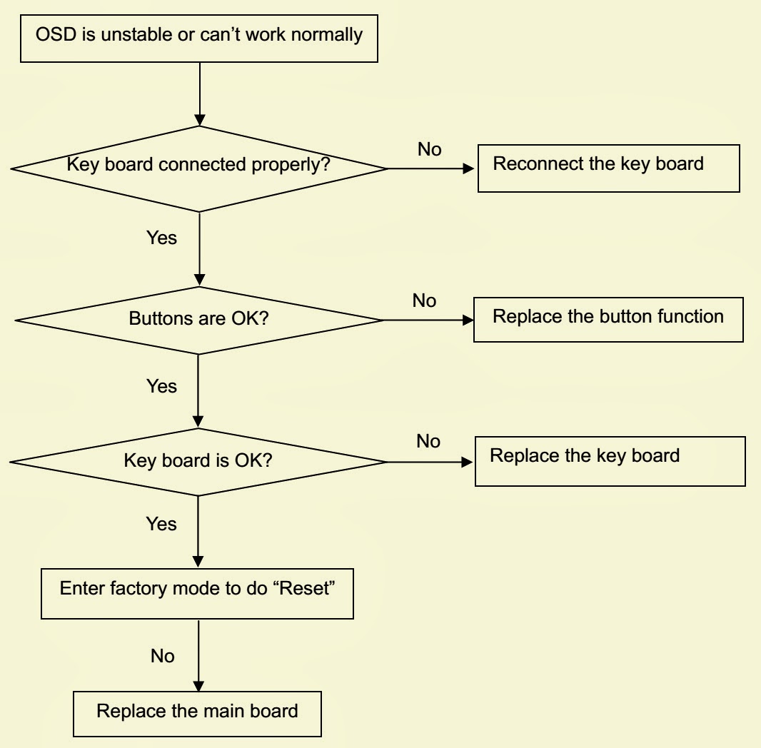
SHARP PN-E601_PN-E521- LED BLINKS – TROUBLESHOOTING_ LCD MONITOR/EXPANSION-BOARD
↧
POWER SUPPLY TROUBLESHOOTING - SHARP PN-E601_PN-E521
↧
↧
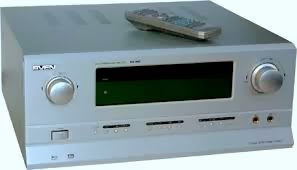
SVEN HR-945 - POWER AMPLIFIER - SCHEMATIC - (Circuit Diagram)
↧
PROLOGY PAS-2150 _ ELITE 2300 - CAR AUDIO - SCHEMATIC [CIRCUIT DIAGRAM]
↧
TOSHIBA 27WL46 - POWER SUPPLY [SMPS] SCHEMATIC (CIRCUIT DIAGRAM)
↧
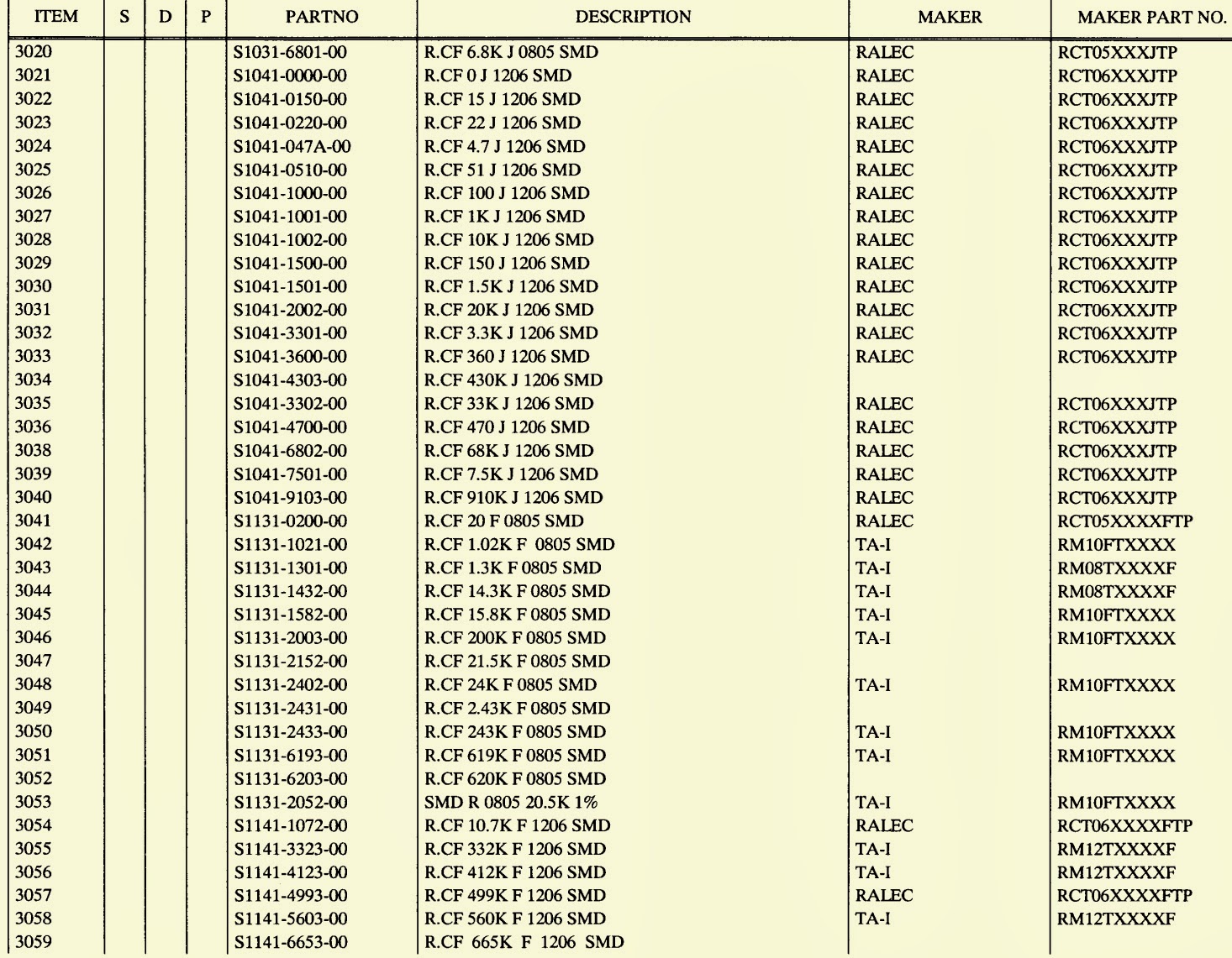
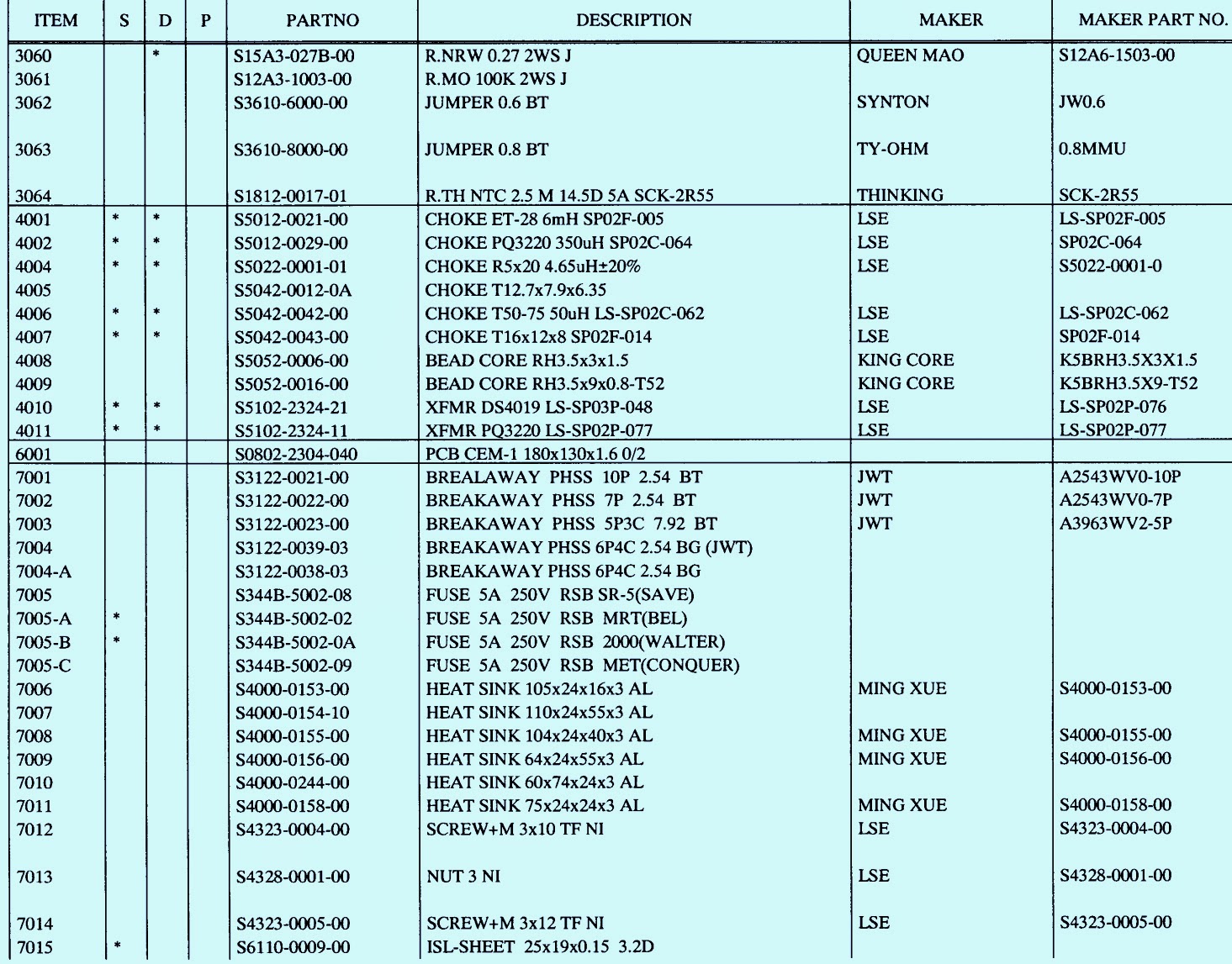
POWER SUPPLY PART LIST-TOSHIBA 27WL46 [See Schematic by previous post]
↧
↧
HOW TO REPLACE LAMP PANASONIC PT-D3500U - PT-D3500E – DLP PROJECTOR
Replacement lamp unit model No.: ET-LAD35 (single bulb) Rating: 300 W
Long-life lamp unit model No.: ET-LAD35L (single bulb) Rating: 160 W
Other lamps than specified above cannot be used. Be sure to use the specified lamp.
REPLACEMENT
Wait until the lamp is cooled sufficiently before replacing the lamp unit.
The lamp used for the light source has its due life. The life of light source lamp used in the main unit is 1500 hours
*1 (when lamp output is HIGH). However, it may happen that the lamp becomes dead (will not light) by the time of 1500 hours *1 depending on the characteristics of individual lamps and working conditions (lamps may reduce their life affected by the times of lighting and the intervals between previous lighting and next lighting). Therefore, it is strongly recommended for the user to keep a spare bulb. If your lamp unit is not replaced after 1300 hours *2 (with the lamp output set at “HIGH”), power supply will be turned off automatically at the time of 1 500 hours *1 entering a standby state. After 1500 hours *1 of initial lighting, power supply is turned off automatically about 10 minutes later, entering a standby state even if it is turned on again.
LAMP MONITOR INDICATION
CLICK ON THE PICTURES TO ZOOM IN
## Be sure to follow steps 8 to 13 in ten minutes after turning on the projector because the projector is turned off in ten minutes if the RUNTIME indication is 1500h or more.
↧
HOW TO ADJUST FLICKER - PANASONIC PT-AE1000U - PT-AE1000E – LCD PROJECTOR
FLICKER ADJUSTMENT
If replacing the optical parts (LCD Panel / LCD block) or A-P.C.Board of this projector, enter the flicker adjustment mode and minimize the flicker.
Select "FLICKER ADJUST" on "EXT OPTION" menu and press "ENTER" button on the main unit or remote control unit.
Note: "DESK setting (red)" is displayed when entering the adjustment mode.
ADJUSTMENT DISPLAY AND CONTENTS
- Setting value is increased and decreased with the right-arrow "►" and left-arrow "◄" buttons. ["◄": Decrease, "►": Increase]
- Adjust the setting value to minimize the flicker on the screen.
Execute the adjustment by 6 patterns below.
- The pattern (adjustment display) is switched with the up-arrow "▲" and down-arrow "▼" buttons. ["▲": Forward direction, "▼": Reverse direction]
- There are 6 patterns of "DESK setting (red)", "DESK setting (blue)", "DESK setting (green)", "CEILING setting (red)","CEILING setting (blue)" and "CEILING setting (green)".
- The setting value is saved into this projector when the pattern is switched.
TO EXIT FLICKER ADJUSTMENT MODE
Press "MENU" button on the main unit or remote control unit.
Note: When "MENU" button is pressed, the setting value at that time is saved into this projector and the adjustment mode is canceled.
↧
SANYO DS-27820 - 27" TV (US) - POWER SUPPLY [SMPS] - SCHEMATIC (CIRCUIT DIAGRAM)
↧

