Quantcast
Channel: Electro help
Viewing all 2033 articles
Browse latest View live

SAMSUNG 753DFX - 76DF - COLOR MONITOR - DISASSEMBLE _ SMPS SCHEMATIC [Circuit Diagram] - TROUBLESHOOTING

$
0
0

DISASSEMBLE
  • Disconnect power cord from the monitor.
  • With a pad beneath it, stand the monitor on its front with the screen facing downward and the base close to you.
  • Remove the Stand from the monitor.
  • Remove 2 screws on the Rear cover.
  • Tilt the monitor by lifting at the rear.
  • Push the Opening jig in to each groove along the top of the monitor until makes a “tak” sound. (2 grooves: Left and Right, Make sure each snap is disengaged.)
  • Pull the Rear Cover up and away from the monitor.
CLICK ON THE PICTURES TO ZOOM IN
SMPS SCHEMATIC

SMPS TROUBLESHOOTING


HOW TO DISASSEMBLE - SAMSUNG - DE17PS - DE19PSQAQ-EDC - TFT LCD MONITOR

$
0
0
DISASSEMBLE
Place monitor face down on cushioned table.
Remove 1 screw from grip on the stand and remove back cover from the stand.
Disconnect cable and remove 4 screws from the stand.
Lift up the stand and insert the opening drive into the grooves at each side and press until it clicks.
CLICK ON THE PICTURES TO MAGNIFY
Disconnect function cable and remove 12 screws from the shield.
Remove the cover front and remove 4 screws from the panel
Remove main board from the panel.

ACER _ BENQ _ 17" CRT MONITOR - MTS1786 - HORIZONTAL OUT & SMPS SCHEMATIC

$
0
0
SMPS SCHEMATIC
HORIZONTAL OUTPUT SECTION
CLICK ON THE SCHEMATICS TO ZOOM IN

SONY KDL-V26A11E – KDL-V32A11E - POWER SUPPLY (G2 BOARD) - SCHEMATIC _ ERROR CODES

$
0
0
G2 BOARD - FOIL SIDE
CLICK ON THE PICTURES TO ZOOM IN
SCHEMATIC
ERROR CODES
The identification of errors within the AT2X chassis is triggered in one of two ways: - 1: Busy or 2: Device failure to respond to IIC. In the event of one of these situations arising the software will first try to release the bus if busy (Failure to do so will report with a continuous flashing LED) and then communicate with each device in turn to establish if a device is faulty. If a device is found to be faulty the relevant device number will be displayed through the LED (Series of flashes which must be counted).

HOW TO DISASSEMBLE - SONY KDL-26BX320 / 321 - LCD TV_Screw Types & Detaila

$
0
0

DISASSEMBLE PROCEDURE
REAR COVER ASSY AND STAND BLOCK _ NECK COVER, NECK AND BASE ASSY
CLICK ON THE PICTURES TO MAGNIFY
G13 BOARD, A BOARD, SWITCH UNIT, VESA BRACKET AND SIDE BRACKET_ SPEAKER BRACKET AND SPEAKER
PANEL SUPPORT, H BOARD, LCD PANEL AND BEZEL ASSY
When replacing LCD Panel or Circuit Boards ensure that all Radiation Sheets and Insulation Sheets are in their correct positions in the TV set.

KDL-32BX320/321, BX420_SONY - LCD TV - DISASSEMBLE PROCEDURE & Screws Details

$
0
0

DISASSEMBLE       [CLICK ON THE PICTURES TO ZOOM IN]
REAR COVER ASSY AND STAND BLOCK_ VESA BRACKET, NECK COVER, NECK AND BASE ASSY
G13 BOARD, A BOARD, SWITCH UNIT AND SIDE BRACKET_ VESA BRACKET, BOTTOM FRAME AND H BOARD
 PANEL SUPPORT, H BOARD, LCD PANEL AND BEZEL ASSY

HOW TO DISASSEMBLE_SONY-KDL-40BX420 - LCD TV _ SERVICE MODE

$
0
0

DISASSEMBLY
REAR COVER ASSY AND STAND BLOCK_ VESA BRACKET, NECK COVER, NECK AND BASE ASSY
CLICK ON THE PICTURES TO ZOOM IN
G13 BOARD, A BOARD, SWITCH UNIT AND SIDE BRACKET _  BOTTOM FRAME AND SPEAKER
PANEL SUPPORT, H BOARD, LCD PANEL AND BEZEL ASSY
SERVICE MODE
Turn on the main power switch to place this set in standby mode.
Press the buttons on the remote commander as follows, and entering service mode.
[Info] àChannel (5)àVolume (+)àPower

SONY - KDL-V26A11E _ KDL-V32A11E - FLAT PANEL CTV – SERVICE POSITION

$
0
0
SERVICE
Lay TV set flat and remove the rear cover. Ensure screen is shielded from damage by lying on protective material.
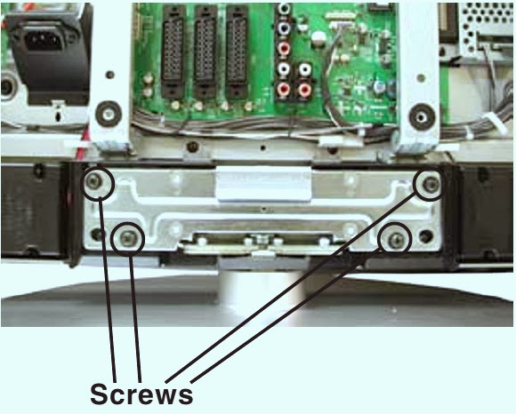
Disassemble the foot from the TV set by removing the four screws circled.
Remove the main brackets.
Disconnect the harnesses connected to boards beneath the main shield case (NP1, BL and N boards). Remove the main shield case.
Remove the NP1, BL and N boards.
Remove the A1board (KDL-V26A11E) or the A2 board (KDL-V32A11E).
Re-fit the foot to the TV set and place the set back in a vertical position. Place a support of approx 35cm high as close as possible to the TV set as shown below.
Arrange the removed circuit boards as shown in the picture. Reconnect the interconnecting harnesses to the circuit boards.
Note: Two new cables are needed to connect the boards in the service position
Cable 1: Part Number: 9-948-020-73 G2 board CN6200, CN6203 to NP1 board CN5801, CN5802
Cable 2: Part Number: 9-948-020-72 N board CN3402 to A1/A2 board CN5105
Using the IF board the A1 board can be mounted vertically as shown in the picture below.
CLICK ON THE PICTURES TO MAGNIFY


PHILIPS - FWM 9000 _ Mini Hi-Fi System - SCHEMATIC - AMP [Amplifier section_Circuit Diagram] - (TDA8954TH)

$
0
0

POWER AMP - SCHEMATICS
CLICK ON THE SCHEMATICS TO ZOOM IN
PCB-TOP
PCB-BOTTOM

HOW TO ENTER SERVICE MODE - SHARP 32K-X2000 - 36K-X2000 - CK32S60 - CK36S60

$
0
0

SERVICE MODE
Before putting unit into the service mode, check that customer adjustments are in the normal mode. Use the reset function in the video adjustment menu to ensure customer controls are in their proper (reset) position.
Service Number Selection
Once in the service mode, press the Ch  /  button on the remote controller or at the set.  The service adjustment number will vary in increments of one, from "S01" to "G06". Select the item you wish to adjust.
Data Number Selection
Press the Vol /  button to adjust the data number.
To enter the service mode and exit service mode.
While pressing the Vol and Ch buttons at the same time, plug the AC cord into a wall socket.  Now the TV set is switched on and enters the service mode.
To exit the service mode, turn the television off by pressing the power button.
SERVICE MODE SCREEN
To call up the service mode, hold down the CH UP and VOL UP keys of the unit at once and plug the AC power cord into a wall outlet. The unit switches on and comes in the service mode.
Now hold down both the CH UP and CH DOWN keys of the unit for 2 seconds or longer. the  default values are written in the EEPROM.
DEFAULT DATA VALUES
CLICK ON THE TABLES TO ZOOM IN

SHARP SCHEMATIC DIAGRAM: POWER and CRT Unit (36K-X2000/CK36S60) - (32K-X2000/CK32S60).

$
0
0

32K-X2000_CK32S60
CLICK ON THE SCHEMATICS TO ZOOM IN
36K-X2000_CK36S60

TOSHIBA 28D8 - MAIN POWER SUPPLY [SMPS] - SCHEMATIC (Circuit diagram)

$
0
0


CLICK ON THE SCHEMATIC TO ZOOM IN

SONY KDL-32EX500 - KDL-37EX500 - KDL-40EX500 - KDL-46EX500 - KDL-55EX500 Series LCD TVs - SELF DIAGNOSTIC MODE & SERVICE MODE

$
0
0

SELF DIAGNOSTIC MODE
For errors with symptoms such as “power sometimes shuts off” or “screen sometimes goes out” that cannot be confirmed, it is possible to bring up past occurrences of failure for confirmation on the screen.
1-487-700-11REMOTE COMMANDER (RM-ED035)
1-487-758-11REMOTE COMMANDER (RM-ED033) EX508.
[To Bring Up Screen Test]
In standby mode, press buttons on the remote commander sequentially in rapid succession as shown below:
DISPLAYàCHANNEL [5]àVOLUME [-] àTV POWER.
Self Diagnostic Display Screen & Descriptions
CLICK ON THE PICTURES TO ZOOM IN
Since the diagnostic results displayed on the screen are not automatically cleared, always check the self-diagnostic screen.  After you have completed the repairs, clear the result display to “0”.
Clearing the Self Check Diagnostic List
Error history and Error count: Press the Channel 8 => Channel 0.
Panel operation time: Press the Channel 7 => Channel 0.
Exiting the Self-diagnostic screen
To exit the Self Diagnostic screen, turn off the power to the TV by pressing the POWER button on the remote or the POWER button on the TV.
HOW TO ENTERING SERVICE MODE
Turn on the main power switch to place this set in standby mode.
Press the buttons on the remote commander as follows, and entering service mode.
Service mode display.
Note: First of all, when you enter Service Mode, you can see “Digital” service mode.
Whenever you press “OPTIONS” or “JUMP” on remote, each service mode is changed. “Digital” à“Chassis” à“Sub”.
TO USE REMOTE CONTROLLER IN SERVICE MODE
After entering service mode, then turn off the power switch.
WHITE BALANCE ADJUSTMENT
Change Data of “Digital” service mode. (“006 WB”category)
  1. Press “0” or “10” on remote toenter WB adjustment mode.
  2. Press number key “1”~”6” directly. “*” stamp move.
  3. Press “12 / enter / select” to decide and advance next step. When returning on the previous page, press “return”.
  4. Change data by number key “0”~”9” directly. (0-255)
  5. Press “12 / enter / select” to save data.  It shows red “WRITE”. It indicates writing is processing. Writing process is done at this point.
SAVE CHANGING DATA
Change Data of “Chassis” or “Sub” service mode
  1. Write data for “Chassis” or “Sub” service mode.  a. Press “Mute” on remote. It shows green “SERVICE” changes to green “WRITE”.  b.Press “0” or “enter” on remote. Green “WRITE” changes to red “WRITE”. It indicates writing is processing.  c. After a while, red “WRITE” changes to green “SERVICE”. Writing process is done at this point.
  2. TV reboot is necessary for applying data change.
CHANGE DATA
Note: “Digital” service mode doesn’t have to save. (except “002 MODEL” category)
1)Change Data of “Digital” service mode. (except“003 DIG_SRV_MODE” category)
a. Press “2 / 5” on remote to select (up / down) category.
b. Press “1 / 4” on remote to select (up / down) Item.
c. Press “0 / 10” on remote to select item.
2)Change Data of “Digital” service mode. (“003 DIG_SRV_MODE”category) “003 DIG_SRV_MODE” is one category of “Digital” service mode.
Note because this operation is special.
a. Press “2 / 5” on remote to select “003 DIG_SRV_MODE”.
b. Press “1 / 4” on remote to select (up / down) Item.
c. Press “0 / 10” on remote to select item.
d. Press number key “1”~”9” directly. “*” stamp move.
e. Press “12 / enter / select” to decide and advance next step. Press, “return”, when returning on the previous page.
3)Write data for “Digital” service mode. (“002 MODEL” category)
Note: This procedure operation, when replaced the B board.
Note: Do not write wrong segment or destination information in Product ID.
When the wrong setting is written, TV may not operate.
000 SEG *** Product ID - segment information
001 DEST*** Product ID – destination information
a. Change data for each model.
b. Press “0” or “enter” on remote. It shows red “WRITE”. It indicates writing is processing.
c. Writing process is done at this point.
SET TO SHIPPING CONDITION
How to do shipping condition.
a. Move to “Digital”service mode.
b. Press “8” on remote. It shows green “SERVICE” changes to green “RST-”.
c. Press “mute” on remote. Added green “EXE” after green “RST-”.
d. Press “0” or “enter” on remote. Green “EXE-RST” changes to red “EXE-RST”. It indicates writing is processing.  After a while, red “EXE-RST” changes to green “SERVICE”. And all LED lights. Writing process is done at this point.
Another way
You can set to shipping condition w/o entering Service Mode.
 “Cursor Up” on remote + “Power Key” on Front panel.

SONY KDL-32/37/40/46/55EX500 Series(AEP/UK) _ LED BLINKING CODES & TROUBLESHOOTING

$
0
0
TRIAGLE CHART
CLICK ON THE PICTURES TO ZOOM IN
NO POWER
STANDBY LED BLINKS 2 TIMES [MAIN POWER ERROR]
3 times blinking (DC Alert, Audio Error and Communication Error)
4 times blinking (Balancer Error)
5 times blinking (T-con Error)
6 times blinking (Backlight Error)
7 times blinking (Temperature Error)
NO PICTURE
NO SOUND
NETWORK MALFUNCTION

LG 50PG20 _ PLASMA DISPLAY _ HOW TO TROUBLESHOOT MAIN POWER SUPPLY [SMPS]

$
0
0

POWER SUPPLY TROUBLESHOOTING
Remember if a voltage is missing check for proper resistance before proceedings.
   Understanding the Power On Sequence when Troubleshooting a possible Power Supply Failure will simplify the process of isolating which circuit board failed to operate properly. In this Section we will investigate the Power on Sequence and examine ways to locate quickly where the failure occurred.
   Check the Power On LED for Operation. A Red LED indicates a presence of 5V STB and AC-ON/DETECT.  Failure of the Power ON LED to light is an indication of loss of 5V STB or AC ON/ Detect remembers the 5V STB and AC-ON/DETECT are developed on the SMPS and sent to the Main Board.
   Listen for Relay Click; the click of the Relay is an indication of RL-ON going high. RL-ON is sent from the Main Board to the SMPS and when present the U701 controls the Relay Operation. RL-ON going high and no Relay is a failure of the SMPS, RL-ON staying low is a failure of the Main Board.
   Relay Operation means that the SMPS if working properly will output the 16V supply to the Main Board.  This voltage will allow the Tuner, Audio and Video Circuits on the Main Board to function, and if connected to an Antenna Input, Audio would be present. If the Relays closed and these supplies failed suspect a problem with the SMPS.
   The next step of operation calls for the M5V_ON line from the Main Board to the SMPS to go high on P803 pin 21. A high on the M5V_ON Line activates the 5V VCC line. Loss of 5V VCC results in no “Raster”, no Display Panel Reset, and no Y, Z, Control or X Board operation. Any of these boards or failure of the SMPS could cause loss of5V VCC and M5V_ON going high. M5V_ON staying low indicates a problem on the Main Board.

   VS-ON is the last step of the Power Sequence and is responsible for bringing the VS and VA Voltages up.  The VS-ON signal pin 20 P803 is sent from the Main Board to the SMPS as a high, VS and VA and full operation of the Display Panel are now enabled. Loss of VS-ON results in loss of VA and VS and no Raster, no Panel Display Reset but Audio would be present. If VS-ON went high and VS and VA where missing the problem could be caused by a failure on the SMPS or a circuit using these voltages. A Resistance check should narrow the possible failures quickly.
STATIC TEST
   This test can confirm the proper operation of the SMPS without the need to exchange the board.  This Power Supply can operate in a No Load State. This means that by applying AC power to CN101 and all other plugs disconnected, this power supply will function. Simply removing P803 (Lower Right-Hand Side of the Board), will cause the “AUTO” Pin 22 to go high from its normal low state allowing the Power Supply to go to full power on mode when AC Power is Supplied. Be careful after this test and make sure the VA and VS lines have discharged before reconnecting the supply cables.
   If either Y-SUS or Z-SUS is causing the power supply to shutdown, unplug the Z-SUS.  This will allow the Y-SUS to function. If you unplug the Y-SUS from the SMPS, and jump the 5V VCC line to the Y- SUS for Control Board Power the Z-SUS will function.
   If the Y-SUS and Z-SUS Boards are working normal, when the SMPS comes up to full power on, “Display Panel Reset” will be visible. Shorting the Auto Pattern Gen. test points at this time should result with test patterns on the screen (if not check for 16V and VA to the X Boards).
For a “Stand-Alone” static test for the Power Supply, apply the usual 2-100Watt light Bulbs test on the Vs output line for a simulated load. If the Power Supply operates in this condition, it is assured it can maintain its output power under load.
Ground the Auto Ground (Pin 22) on P803
AC Power Applied AC Det (Pin 18) and 5V STB (Pins 9 ~ 12) are 5V.
100Ω¼ watt resistor added from 5V STB (Pins9 ~ 12) to RL ON (Pin 19) closes relay RL101 turning on the 16V Supply.
100Ω¼ watt resistor added from 5V STB (Pins 9 ~ 12) toM5V_ ON (Pin 21) brings the 5V VCC line high.
100Ω¼ watt resistor added from 5V STB (Pins 9 ~ 12) toVS _ON (Pin 20) bringsthe VA and VS Lines high.
USING BULBS AS LOAD
   Unplug all connectors.  Using two 100W light bulbs [filament type only], attach one end to Vs P801 pin 1 & 2 and the other end to chassis ground.  Apply AC to CN101.  If the light bulbs turn on, allow the SMPS to run for several minutes to be sure it will operate under load.  If this test is successful and all the other voltages are generated, can be assured the power supply is OK.
Note:  The light bulb test is not necessary for the SMPS to turn on and stay on.  This SMPS will run without a load.  But, it is necessary to test the SMPS under load.
CLICK ON THE PICTURES TO MAGNIFY


Y DRIVE BOARD TROUBLESHOOTING - LG PLASMA TV 50PG20

$
0
0

Y-DRIVE BOARD
Y-Drive Board works as a path supplying the Sustain and Reset waveforms, which are made in the Y-SUSTAIN B/D and sent to the Panel through SCAN DRIVER IC’s.  The Y Drive Boards supply a waveform, which selects the horizontal electrodes sequentially.

50PG20 uses 8 DRIVER ICs on 2 Boards (TOP, BOTTOM: 4 each).  50G1 Panel has 768 Vertical lines of resolution (Horizontal Grids determine V Resolution)
4 Ribbons (Tabs) separated into 2 = 192 grids per tab.
8 Ribbon inputs to 4 Tabs = 96 lines per ribbon input
2 Buffers per Ribbon input = 96 lines per ribbon input.
5 Volts (Floating Ground) 5VFG and Logic Signals from Y-SUS Board are supplied to the Top Drive Board on Connector P100.
5 Volts (Floating Ground) 5VFGinput also enters the Bottom Y Drive Board at P200.
CLICK ON THE PICTURES TO ZOOM IN
To remove the Ribbon Cable from the connector first carefully lift the Locking Tab from the back and tilt it forward (lift from the outside edge as shown).
Lift up the entire Ribbon Cable gently to release the Tabs on each end.  Gently slide the Ribbon Cable free from the connector.
To re-install the Ribbon Cable carefully slide it back into the slot, be sure the Tab is seated securely and press the Locking Tab back to the locked position.
The Ribbon Cable is clearly improperly seated into the connector. You can tell by observing the linearity.  Note the cable is crooked. In this case the Tab on the Ribbon cable was improperly seated at the bottom. This can cause bars, lines, and intermittent lines abnormalities in the picture. Remove the ribbon cable and re-seat it correctly.
Y Drive Upper Troubleshooting
Using the “Diode Test” on the DVM, check the pins for shorts or abnormal loads.
Y Drive Lower Troubleshooting.
Using the “Diode Test” on the DVM, check the pins for shorts or abnormal loads.
YOU CAN CHECK ALL 8 BUFFER ICs USING THIS PROCEDURE

LED BLINKING CODES - LG50PG20 - PLASMA TV - CONNECTOR VOLTAGE DETAILS

$
0
0

VISUAL CLUES FOR FAULT BY LED BLINKS
This information pertains to “Shorted” voltage lines, not Open voltage lines
  • STBY 5V Short or Open: Power LED does not light in stand by. No Power button function.
  • AC Detect Open (Shorted Reset Line): Power LED is lit all Blue, 5V STBY OK. Power Button has no effect.
  • M5V Vcc Short: Apply AC Power, goes to flashing Red and Blue. Relay Clicks “On and Off”
  • 12V Short: Power LED is lit Red in stand by. At Power On, Power LED flashes 2 times Blue then 1 Long Blue goes back to Red. Relay clicks off immediately.
  • 16V Short: Apply AC Power , Power LED flashes Blue. Relay clicks rapidly on and off.
  • Va or Vs Short: Power LED is lit Red in stand by. At Power On, goes to Blue. Relay closes. Power LED blinks blue twice and3rd blink stays blue. Relay opens, LED goes to red. Power Supply outputs 16V,12V and 5Vcc,drops to 0V after the relay opens. No Va or Vs. With Relay closed, 330V OK, then when relay opens, it drops to 155V.
CN101 and P801 Pin ID and Voltages
Voltage and Diode Test Measurements for the SMPS.  All voltages from a working unit.
Connector: CN101
Pin Number: 1 & 3.
Standby: 120VAC
Run: 120VAC
Resistance: 480K
CLICK ON THE TABLES TO MAGNIFY

QUQD 66 - CD PLAYER - POWER SUPPLY SCHEMATIC - MECHANISM EXPLODED VIEW

$
0
0
POWER SUPPLY SCHEMATIC 
Click the pictures to see bigger size
CHANGING MAINS VOLTAGE
The Quad CD Player is normally supplied for 220/240V AC operation.  For 110/127 operation the mains transformer can be set by the wire links on the main PCB, the mains input power fuse must also be replaced with the correct rating.,  Facilities are provided for operation from four different voltage ranges,  110V, 127V, 220V and 240V settings are suitable for most applications but for 100V supplies (Japan) the 110V taps should be used.
#  Remove main PCB assembly.
## Solder links as shown below and fit correctly rated fuse
220/240V à 160mA delay – part number UMA16DA
110/127V à 315 mA delay – part number UMA315D
EXPLODED VIEW TO CD MECHANISM & PARTS LIST

TOSHIBA 15V31F - POWER SUPPLY[SMPS] & DEFLECTION SCEMATIC [Circuit Diagram]

$
0
0
SMPS SCHEMATIC
CLICK ON THE SCHEMATICS TO ZOOM IN
DEFLECTION

HOW TO ENTER SERVICE MODE _ TOSHIBA 15V31F _ CRT TV

$
0
0
SERVICE MODE
This unit provided with the following SERVICE MODES so you can repair, examine and adjust easily.
To enter the Service Mode, press both set key and remote control key for more than 2 seconds.
CLICK ON THE TABLES TO MAGNIFY
CONFIRMATION OF HOURS USED
POWER ON total hours can be checked on the screen. Total hours are displayed in 16 system of notation.
NOTE: If you set a factory initialization, the total hours is reset to "
  • Set the VOLUME to minimum.
  • Press both VOL. DOWN button on the set and Channel button (6)on the remote control for more than 2 seconds.
  • After the confirmation of using hours, turn off the power.
WHEN REPLACING EEPROM (MEMORY) IC
If a service repair is undertaken where it has been required to change the MEMORY IC, the following steps should be taken to ensure correct data settings while making reference to TABLE.
The unit will now have the correct DATA for the new MEMORY IC.
  1. Enter DATA SET mode by setting VOLUME to minimum.
  2. Press both VOL. DOWN button on the set and Channel button (6)on the remote control for more than 2 seconds. ADDRESS and DATA should appear as FIG.
  3. ADDRESS is now selected and should "blink". Using the VOL. +/- button on the remote, step through the ADDRESS until required ADDRESS to be changed is reached.
  4. Press OK to select DATA. When DATA is selected, it will "blink".
  5. Again, step through the DATA using VOL. +/- button until required DATA value has been selected.
  6. Pressing OK will take you back to ADDRESS for further selection if necessary.
  7. Repeat steps 3 to 6 until all data has been checked.
  8. When satisfied correct DATA has been entered, turn POWER off (return to STANDBY MODE) to finish DATA input.
After the data input, set to the initializing of shipping.
  • Turn POWER on.
  • Press both VOL. DOWN button on the set and Channel button (1)on the remote control for more than 2 seconds.
  • After the finishing of the initializing of shipping, the unit will turn off automatically.
NOTE: No need setting for after INI 16 due to the adjustment value.
Check if the fixed values of the each adjustment items are set correctly referring below.
To check for the fixed values of the RF (60Hz), indicate the adjustment mode screen while input the 60Hz video signal.

Viewing all 2033 articles
Browse latest View live


<script src="https://jsc.adskeeper.com/r/s/rssing.com.1596347.js" async> </script>