↧
PANASONIC - DVD DVD-S325E_DVD-S325EG - DL4.5 Mechanism Series – POWER SUPPLY [SMPS] – Schematic (Circuit Diagram)
↧
SERVICE MODE - PANASONIC DVD-S325E - SELF DIAGNOSTIC FUNCTION
An error code will be canceled if a power supply is turned OFF.
When FROM or Module P.C.B. is replaced, be sure to write the present value into the player as the initial setting of laser drive current
Writing method :
a. Press the "PAUSE" button on the remote control unit while pressing the "PLAY" and "OPEN/CLOSE" buttons on the player.
b. Turn off the second power.SERVICE MODE
Pressing various button combinations on the player and remote control unit can activate the service modes.
Please carry out your operation based on the remote control supplied with Panasonic DVD player of previous models.
CLICK ON THE TABLES TO MAGNIFY
Sales demonstration lock function
This function prevents discs from being lost when the unit is used for sales demonstrations by disabling the disc eject function. "LOC" is displayed on the unit, and ordinary operation is disabled.
Setting
The sales demonstration lock is set by simultaneously pressing PLAY and OPEN/CLOSE buttons on the player and QUICK REPLAY button on the remote control unit for 1 second or longer.
Cancellation
The lock can be cancelled by the same procedure as used in setting. ("UNLOC" is displayed on cancellation. Disconnecting the power cable from power outlet does not cancel the lock.)
Precautions
Do not disconnect the power plug from the outlet with the tray still open, and then close the tray manually.
↧
↧
PHILCO[PHILIPS] PH 671- MICRO-SYSTEM – SCHEMATIC (Circuit Diagram) & Exploded View - TDA7265
↧
SONY DVP C-600D - SMPS (POWER SUPPLY)_SCHEMATIC (Circuit Diagram)
↧
YAMAHA S-2700 - SMPS [POWER SUPPLY] - SCHEMATIC - DVD AUDIO/VIDEO SA-CD PLAYER
SMPS SCHEMATIC
CLICK ON THE SCHEMATIC TO ZOOM IN
TRADE MODE
In the TRADE mode, the tray open/close function is stopped temporarily.
Setting TRADE mode
- Connect the power cable of the main unit to the AC outlet.
- Press the “POWER ON/OFF” key of the main unit and press the “STANDBY/ON” key of the main unit or remote controller to turn on the power.
- Press the “OPEN/CLOSE” key of the main unit to open the tray.
- Place a disc in the tray and open the “OPEN/CLOSE” key of the main unit to close the tray.
- While pressing the “SKIP+/SEARCH+” key of the main unit and press the “STOP” key for 3 seconds or longer.
- When the TRADE mode is set, [TRADE ON] is displayed which then returns to the normal display.
Press the “OPEN/CLOSE” key, and [TRAY LOCKED] is displayed
Canceling TRADE mode
- With a disc set in the tray, while pressing the “SKIP+/SEARCH+” key of the main unit and press the “STOP” key for 3 seconds or longer.
- When the TRADE mode is cancelled, [TRADE OFF] is displayed which then returns to the normal display.
- When no picture is displayed even though the main unit and TV monitor are connected with the HDMI cable
- Press the “STOP” key of the main unit or on the remote control twice.
- While pressing the “STOP” key of the main unit, press the “PLAY” key for 3 seconds or longer. [HDMI RESE] is displayed of the main unit, which then returns to the normal display.
When no picture is displayed or picture is displayed but not properly even though the main unit and TV monitor are connected with the video pin cable or the like
- Press the “EJECT” key to open the tray.
- Press the “CLEAR” key on the remote control.
- Press the “2”, “5”, “8”and “0”keys on the remote control.
- Press the “AUDIO” key on the remote control.
↧
↧
YAMAHA DVD S-1700 - SMPS (Power Supply) SCHEMATIC [Circuit Diagram] - DVD AUDIO/VIDEO SA-CD PLAYER
↧
LG MCT-705 - MAIN AMP & POWER SUPPLY _ SCHEMATIC - (CIRCUIT DIAGRAM)
↧
HOW TO TROUBLESHOOT-SAMSUNG LN SERIES LCD TV - NO POWER - NO VIDEO
APPLICABLE TO: LN26B450C4M _ LN32B450C4M _ LN37B450C4M _ LN40B450C4M _LN32B460B2M_LN32B530P2M_ LN37B530P2M _ LN40B530P2M _ LN46B530P2M
NO POWER
Symptom
- The LEDs on the front panel do not work when connecting the power cord.
- The SMPS relay does not work when connecting the power cord.
- The units appear to be dead.
The IP relay or the LEDs on the front panel does not work when connecting the power cord if the cables are improperly connected or the Main Board or SMPS is not functioning. In this case, check the following:
- Check the internal cable connection status inside the unit.
- Check the fuses of each part.
- Check the output voltage of SMPS.
- Replace the Main Board.
DIAGNOSTICS
CLICK ON THE PICTURES TO MAGNIFY
No Video (Analog PC signal)
Audio is normal but no picture is displayed on the screen.
- Check the PC source
- Check the SEMS12
- This may happen when the LVDS cable connecting the Main Board and the Panel is disconnected.
DIAGNOSTICS
↧
LG & AKIRA - CT-29K36ET- SMPS (Power Supply) - AUDIO OUTPUT - SCHEMATIC [Circuit Diagram] - HOW TO ENTER SERVICE MODE
STR-6656 – LTV817M – SE115N – LA4282
SMPS SCHEMATIC.
CLICK ON THE SCHEMATICS TO ZOOM IN
How to enter into the Line Service Mode with a Remote control.
- Power off.
- Press the Red button.
- Press the Green button.
- Press the Yellow button.
- Press the Cyan button.
- Press the OK button.
- Power On
- At SVC mode, press the Yellow colored button the SVC remocon. And then, deflection data adjustment OSD(SVC2 mode) will be displayed.
- Press Channel UP/DOWN button for desirous function Adjustment.
- Press Volume UP/DOWN button to adjust the data.
- Tune the TV set to receive a PAL B/G Digital pattern.
Adjust so that the boundary line between upper and lower half is in accord with geometric horizontal center of the CPT.
VA (Vertical Amplitude)
Adjust so that the circle of a digital circle pattern may be located within the effective screen of the CPT.
SC (Vertical OSO Correction)
Adjust so that all distance between each horizontal lines are to be the same.
VS (Vertical Shift)
Adjust so that the horizontal center line of a digital circle pattern is in accord with geometric horizontal center of the CPT.
HS (Horizontal Shift)
Adjust so that the vertical center line of a digital circle pattern is in accord with geometric vertical center of the CPT.
EW (Horizontal Width)
Adjust to that a digital circle pattern looks like exact circle.
EP (East-west Parabola)
Adjust so that middle portion of the outermost left and right vertical line looks like parallel with vertical lines of the CPT.
EC (East-west Corner)
Adjust so that the vertical line at every 4 corners of the screen looks like parallel with the vertical lines of the CPT.
ET (East-west Trapezium)
Adjust to make the length of top horizontal line same with it of the bottom horizontal line.
POP (POP Position)
Adjust until the distance between POP and main picture becomes about 1mm.
↧
↧
SAMSUNG LN-Series - LN26 / LN32 / LN37 / LN40 - LCD TVS - HOW TO ENTER SERVICE MODE
ENTERING FACTORY MODE
To enter ‘Service Mode’ Press the remote -control keys in this sequence:
If you do not have Factory remote - control
Power OFFàMUTEà 1 à 8à2àPower OnHow to Access Service Mode.
Using the Customer Remote
- Turn the power off and set to stand-by mode.
- Press the remote buttons in this order; POWER OFF-MUTE-1-8-2-POWER ON to turn the set on.
- The set turns on and enters service mode. This may take approximately 20 seconds.
- Press the Power button to exit and store data in memory. If you fail to enter service mode, repeat steps 1 and 2 above.
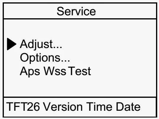
How to enter the hidden factory mode.
a. into the factory mode
b. move the tap to Advanced
c. key input : 0 + 0 + 0 + 0
hidden menu : Advanced.
Buttons operations within Service Mode
Method of Color Calibration (AV)
Apply the NTSC Lattice (N0. 3) pattern signal to the AV IN 1 port
Press the Source key to switch to “AV1” mode
Enter Service mode
Select the “Calibration” menu
Select the “AV Calibration” menu.
In “AV Calibration Off” status, press the “►” key to perform Calibration.
When Calibration is complete, it returns to the high-level menu.
You can see the change of the “AV Calibration” status from Failure to Success.
Method of Color Calibration (Component)
Apply the 720p Lattice (N0. 6) pattern signal to the Component IN 1 port
Press the Source key to switch to “Component1” mode
Enter Service mode
Select the “Calibration” menu
Select the “DTV Calibration” menu.
In “DTV (Component) Calibration Off” status, press the “►” key to perform Calibration.
When Calibration is complete, it returns to the high-level menu.
You can see the change of the “Comp Calibration” status from Failure to Success.
Method of Color Calibration (PC)
Apply the VESA XGA Lattice (N0. 21) pattern signal to the PC IN port
Press the Source key to switch to “PC” mode
Enter Service mode
Select the “Calibration” menu
Select the “PC Calibration” menu.
In “PC Calibration Off” status, press the “►” key to perform Calibration.
When Calibration is complete, it returns to the high-level menu.
You can see the change of the “PC Calibration” status from Failure to Success.
Method of Color Calibration (HDMI)
Apply the 720p Lattice (N0. 6) pattern signal to the HDMI1/DVI IN port
Press the Source key to switch to “HDMI1” mode
Enter Service mode
Select the “Calibration” menu
Select the “HDMI Calibration” menu.
In “HDMI Calibration Off” status, press the “►” key to perform Calibration.
When Calibration is complete, it returns to the high-level menu.
You can see the change of the “HDMI Calibration” status from Failure to Success.
↧
DISASSEMBLY - SAMSUNG - LN26B - LN32B - LN37B - LN40B - LN46B - LCD TV
STAND
Place the TV face down on cushioned table. Remove screws from the Stand. Remove stand.
CLICK ON THE PICTURES TO MAGNIFY
Remove the screws of rear-cover.
Lift up the rear-cover.
Remove the screws of IP and main board.
Remove the speakers and screws of inlet socket.
Remove the screws of Stand BKLT. Lift up the Stand BKLT.
Remove the screws on Panel.
↧
GRADIENTE - TV NEXT-29L - SMPS (Power Supply Section) - SCHEMATIC (Circuit Diagram) - STR-6656
↧
VIEWSONIC NextVision – N2010M – SMPS (Power Supply) SCHEMATIC (Circuit Diagram) - SERVICE MODE
SERVICE MODE
- Power turn on Press “CH▼” and “CH▲” key then release “CH▼” and “CH▲” key press “menu” key go to factory mode.
- Move the color bar to “ EPP Init”, then press “ ENTER” key.
- Move the color bar to “ EXIT” press “ENTER” key quit factory mode, then power OFF/ON.
EEPROM Initial: Only after EEPROM replacement
- Power turn on Press “CH▼” and “CH▲” key then release “CH▼” and “CH▲” key press “MENU” key go to factory mode.
- Move the color bar to “ EPP Init”, then press “ ENTER” key.
- Move the color bar to “ EXIT” press “ENTER” key quit factory mode, then power OFF/ON.
SMPS SCHEMATIC
PWB-TOP
PWB-BOTTOM
CLICK ON THE PICTURES TO ZOOM IN
↧
↧
PANASONIC TX-26LXD65F - TX32LXD65F - SMPS (Power Supply) SCHEMATIC (Circuit Diagram) LCD TV
↧
HOW TO ENTER SERVICE MODE - PANASONIC TX32LXD65F – TX26LXD65F - SELF CHECK MODE
SELF CHECK
- Self-check is used to automatically check the bus lines and hexadecimal code of the TV set. To enter Self-Check mode, keep pressing the STATUS button on the remote control and press the down (-/V) button on the TV set. To exit Self Check, switch off the TV set at the power button.
- If the CCU ports have been checked and found to be incorrect or not located then " - - " will appear in place of "O.K.".
SERVICE MODE
Set the Bass to maximum position, set the Treble to minimum position then keep pressing the INDEX button on the remote control and press the down button (-/V) on the TV set, this will place the TV set into the Service Mode 1.KEY COMMAND
- Press the RED / GREEN buttons to step ▲/▼ through the functions.
- Press the YELLOW / BLUE buttons to alter the function values, to alter White Raster use +/- buttons.
- Press the OK button after each adjustment has been made to store the required values.
- To exit the Service Mode, press the "N" button.
Click on the tables to Magnify
↧
SANYO LCD-27XL2 – LCD32XL2 - POWER SUPPLY SCHEMATIC
↧
SAMSUNG LN26B450 - LN32B450 - LN37B450 - LN40B450 - CONNECTOR FUNCTIONS - T-Con Board SVC Parts Code for each Model
WIRING DIAGRAM-CONNECTORS - PART NUMBERS - LN26B450C4M(HD) - LN32B450C4M(HD) - LN37B450C4M(HD) - LN40B450C4M(HD) - LN32B460B2M(HD)
CONNECTOR FUNCTIONS
IP --> CN2001 Supply main power from IP,SMPS to Main Board.
Defective symptom: No picture, disable Power On/Off.
Panel --> CN11020_FHD, CN11009_DH. The LVDS signal transferred Panel to Main Board.
Defective symptom: No picture but normal sound.CABLES & PART-CODES
CLICK ON THE PICTURES TO ZOOM IN
T-Con Board SVC Parts Code for each Model
↧
↧
TOSHIBA 17MB16P - TFT LCD TV - SERVICE MODE - ADJUSTMENTS
SERVICE MENU
All system, geometry and white balance alignments are performed in production service mode.
Before starting the production mode alignments, make sure that all manual adjustments are done correctly.
To start production mode alignments enter the main menu by pressing “M” button and then press the digits 4, 7, 2 and 5 respectively.
The following menu appears on the screen.After entering the Service menu, you can access its items by pressing “▲/▼” buttons. In order to enter selected menu, use “◄/►” buttons.
To exit the service menu press “M” button.
Entire service menu parameters of TFT TV are listed below.
MENU SETTING ADJUST
In order to enter Adjust menu, move the cursor to Adjust…parameter by pressing “▲/▼” buttons in Service Menu and press “◄/►” button. The following menu appears on the screen.
There are no items for adjustment in ADJUST menu for now.
OPTION SETTINGS
In order to enter Options menu, move the cursor to Options…parameter by pressing “▲/▼” buttons in Service Menu and press “◄/►” button. The following menu appears on the screen.
There are 50 items in the OPTIONS menu, but 10 of them are seen when you first enter the menu. Using “▲/▼” buttons remaining items can be seen.
ADJUSTMENT MENU
There are 50 items in the OPTIONS menu, but 10 of them are seen when you first enter the menu. Using “▲/▼” buttons remaining items can be seen.
Avl > On/Off
Top TXT > On/Off
Fast TXT > On/Off
TXT Lang > Switches between Teletext Language Groups. Min. Value: 0000 00000 Max. Value: 0004 00004
IF Freq. > Adjusts the IF Frequency value. Min. Value: 0000 00000 Max. Value: 00FF 00255
Sound > On/Off
Carrier > On/Off
RC_Options > Adjusts the Remote Control type. The values are: 1: RCMM standard remote control. 2: Metz RC 3: Toshiba RC 4: Credit card 2025. Values greater than 4 are invalid and standard RC will be chosen automatically.
AV-1 > On/Off
AV-2 > On/Off
S-VIDEO > On/Off
AV-3 > On/Off
PC > On/Off
MENU > On/Off Enables / disables semi-transparent MENU.
MIX > Enables / disables teletext MIX mode. Enable: 00000001 Disable: 00000000
HOTEL MODE > Enables /disables Hotel mode feature. Enable: 00000001 Disable: 00000000
X > Not used.
OTHER > Adjusts the standard value for APS for Eastern European countries. The values are: 0: BG standard 1: DK standard.
X > Not used.
LDLY > Adjusts the Luna / chroma Delay value. Min. Value: 0000 00000 Max. Value: 0008 00008.
AGC > Adjusts the Automatic Gain Control value. Min. Value: 0000 00000 Max. Value: 00FF 00255
APS WSS TEST MENU
In order to enter Aps Wss Testmenu, move the cursor to Aps Wss Test parameter by pressing “▲/▼” buttons in Service Menu and press “◄/►” button. The following menu appears on the screen.
There are 7 items in the Aps Wss Test menu.
Programme
Search
VPS
Pdc Format 1
Pdc Format 2
Name
Wss
↧
HARMAN/KARDON - HKTS 200/220 - SUB-WOOFER - SCHEMATIC [Circuit Diagram]
↧
HARMAN/KARDON - HS-230 - HS250 HTS - POWER SUPPLY [SMPS] - SCHEMATIC [Circuit Diagram]
↧