↧
TCL LCD32B 5H - POWER SUPPLY [SMPS] SCHEMATIC & TROUBLESHOOTING
↧
TCL 21288 - VCT3831 - (TDA8172 - MC44608) - TV - CIRCUIT DIAGRAM [SCHEMATIC]
↧
↧
PHILCO [PHILIPS] - SV VCD – PH190N & PH190 HDMI _ POWER SUPPLY [SMPS] SCHEMATIC (Circuit Diagram)
↧
SONY KV-20FS12 - 21FE12A/C - SERVICE MODE _ ADJUSTMENT ITEMS _ DATA VALUE TABLE
Applicable to SONY KV-20FS12_20FV12_21FE12A/C_21FM12_21FV12/C
SETTING SERVICE ADJUSTMENT MODE
- Standby mode (power off).
- Press the buttons on the remote control [DISPLAY >CHANNEL-5 > VOLUME +> POWER] (On the Remote Commander (press each button within a second). The CRT displays the item being adjusted.
- Press [1] or [4] on the Remote Commander to select an item.
- Press [3] or [6] on the Remote Commander to change the data.
- Press [MUTING] then [ENTER] to save into the memory.
- Press [8] then [ENTER] on the Remote Commander to initialize. Carry out this step when adjusting IDs 0–4 and when replacing and adjusting IC1003.
- Turn set off then on to exit service adjustment mode.
** VSS = 1 for US & CND, VSS=0 for Other
*** CDMD= 3 for US & CND, CDMD = 0 for Other
**** KV-21FE12A,KV-21FE12C,KV-21FV12C=1; Others =0
*****BBE HIGHFIX DATA: KV-21FV12/21FV12C= 8; Others = 4
No. 1–100 show the order that each adjustment mode may be selected while in service mode. Data Range shows the range of possible settings for each adjustment mode. Initial Data shows the standard settings for each adjustment mode.
ADJUSTMENT ITEMS
CLICK ON THE TABLES TO MAGNIFY
ID MAP
↧
PANASONIC TC-26LX70L - TC-32LX70L - LCD TV - SERVICE MODE - SELF CHECK MODE - LED BLINKING CODES
SELF CHECK FUNCTION
Use the self-check function to test the unit.
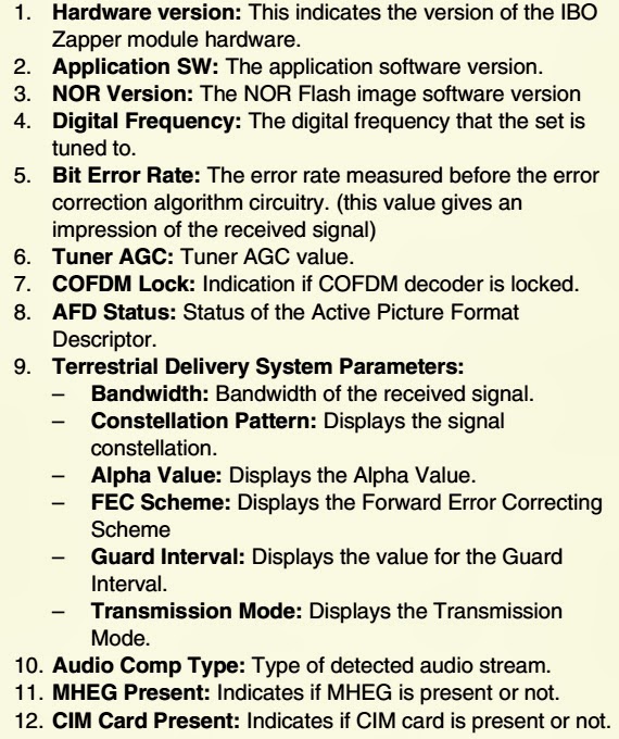
Checking the IIC bus lines & Power LED Blinking timing.
Check of the IIC bus lines [How to access]
Produce TV reception screen, and while pressing [VOLUME ( - )] button on the main unit, press [SLEEP] button on the remote control for more than 3 seconds.
To Exit: Press the POWER button twice (off/on) to return to the normal screen.
SCREEN DISPLAY
Check Point
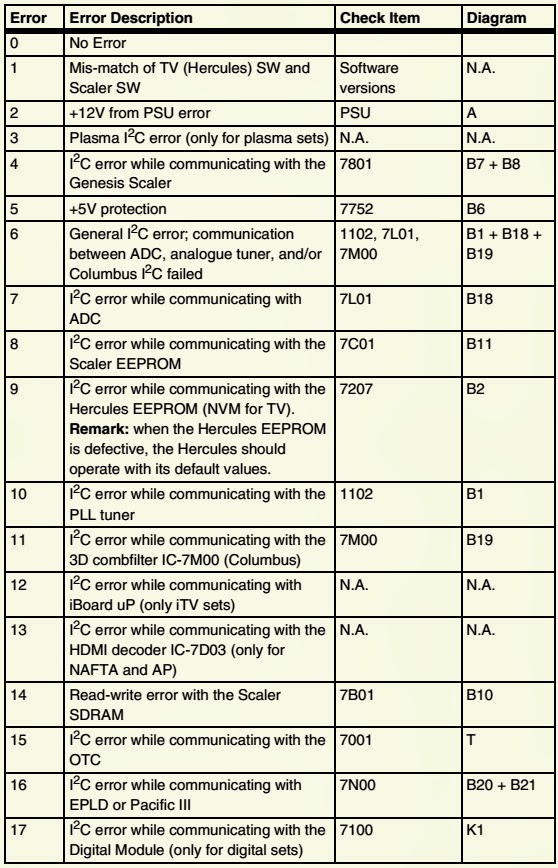
Confirm the following parts if NG was displayed.
CLICK ON THE CHARTS TO MAGNIFY
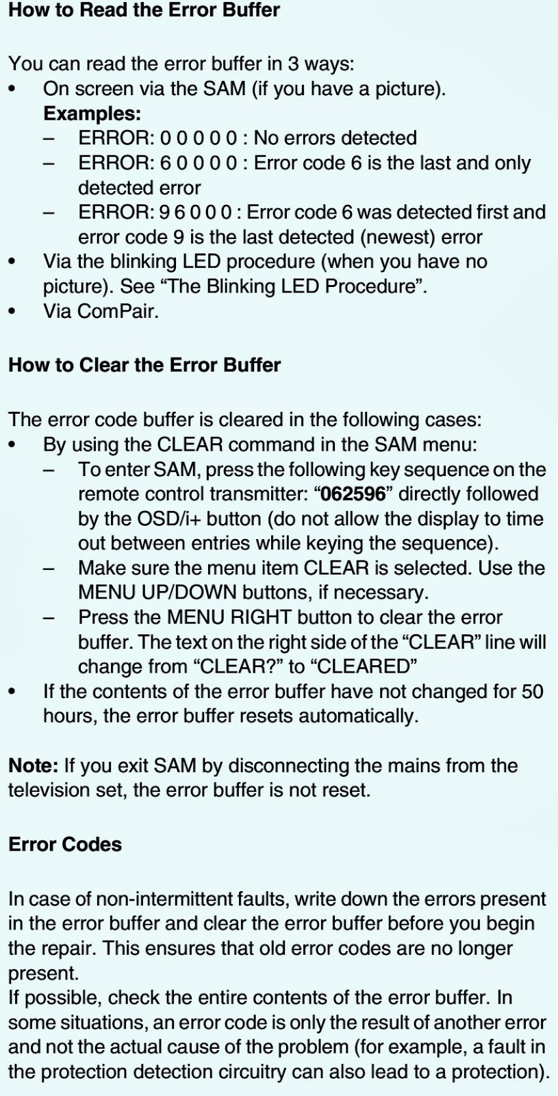
POWER LED BLINKING TIMING CHART
When an abnormality has occurred the unit, the protection circuit operates and reset to the stand by mode. At this time, the defective block can be identified by the number of blinks of the Power LED on the front panel of the unit.
NO POWER - TROUBLESHOOT
There are following 2 states of No Power indication by power LED.
No lit
Red is lit then turns red blinking a few seconds later.
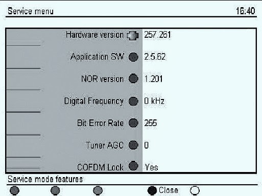
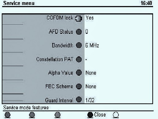
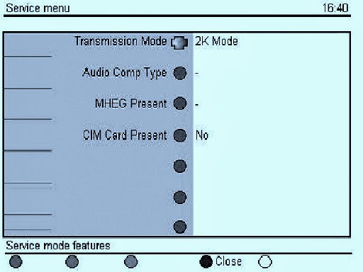
SERVICE MODE
To enter into Service Mode
While pressing [VOLUME ( - )] button of the main unit, press [RECALL] button of the remote control three times within 3 seconds.
Key commands
“1” button...Main items Selection in forward direction
“2” button...Main items Selection in reverse direction
“3” button...Sub items Selection in forward direction
“4” button...Sub items Selection in reverse direction
“VOL” button...Value of sub items change in forward direction ( + ), in reverse direction ( - )
To exit Switch off the power with the [POWER] button on the main unit or the [POWER] button on the remote control.
Contents of adjustment mode
Value is shown as a hexadecimal number.
Preset value differs depending on models.
After entering the adjustment mode, take note of the value in each item before starting adjustment.
Voltage chart of AP-board.
UNIVERSAL REMOTE CONTROL SETUP CODE LIST
10054, 10250, 10051, 11969, 11968, 11947, 11946, 11941, 11919, 11650, 11480, 11410, 11335, 11310, 11291, 11177, 11175, 11168, 10650, 10508, 10367, 10226, 10208, 10163, 10161, 10055, 10037
1121, 1224, 1313, 1221 0264 0412 0037 0217 0377 0218 0698,0556
116 117 135 223 242 316 386 421 436 440 441 444 726
↧
↧
PHILIPS PLASMA - 42PF5521D – 42PF7521D – 50PF7521D - SERVICE MODE - ERROR CODES
SERVICE MODE [Digital customer service mode]
- Press the ‘Digital menu’ button on the remote control to activate digital user manu [Setup]
- Activate the ‘Information’ sub menu (via the ‘down’ and ‘right’ cursor buttons)
- In the ‘Information sub-menu’, press the following buttons ‘GREEN RED YELLOW 9 7 5 9’. Then the service menu will appear.
CLICK ON THE PICTURES TO MAGNIFY
MENU EXPLANATION
TO EXIT
Press the BLUE button on the remote control.
ERROR CODES
ERROR CODE - OVERVIEW
↧
TOSHIBA LCD - LC3251FDA – LC4051FDA – LC4651FDA – LC5551FDA - SMPS - SCHEMATICS
↧
SHARP XR-10X-L - XR-10S-L - XG-MB50X-L - HOW TO REPLACE LAMP - TIMER RESET
HOW TO REPLACE LAMP
[Applicable to Sharp DLP projectors - XR-10X-L - XR-10S-L - XG-MB50X-L - XR-11XC-L - XR-HB007X-L]
[Applicable to Sharp DLP projectors - XR-10X-L - XR-10S-L - XG-MB50X-L - XR-11XC-L - XR-HB007X-L]
This projector utilizes a pressurized mercury lamp. A loud sound may indicate lamp failure. Lamp failure can be attributed to numerous sources such as: excessive shock, improper cooling, surface scratches or deterioration of the lamp due to a lapse of usage time. The period of time up to failure largely varies depending on the individual lamp and/or the condition and the frequency of use. It is important to note that failure can often result in the bulb cracking.
When the lamp replacement indicator and on-screen display icon are illuminated, it is recommended that the lamp be replaced with a new one immediately, even if the lamp appears to be operating normally.
Should the lamp break, there is also a possibility that glass particles may spread inside of the projector. In such a case, it is recommended you contact your nearest Sharp Authorized Projector Dealer or Service Center to assure safe operation.
Should the lamp break, the glass particles may spread inside the lamp cage or gas contained in the lamp may be vented into the room from the exhaust vent. Because the gas in this lamp includes mercury, ventilate the room well if the lamp breaks and avoid all exposure to the released gas. In case of exposure to the gas, consult a doctor as soon as possible.
Replacing the Lamp
Make sure that you remove the lamp unit by the handle. Do not touch the glass surface of the lamp unit or the inside of the projector.
To avoid injury to yourself and damage to the lamp, make sure you carefully follow the steps below.
Do not loosen other screws except for the lamp unit cover and lamp unit.
- Press STANDBY/ON on the projector or STANDBY on the remote control to put the projector into standby mode. Wait until the cooling fan stops.
- Disconnect the power cord. Unplug the power cord from the AC socket. Leave the lamp until it has fully cooled down (about 1 hour).
Remove the lamp unit cover.
Turn the projector over. Loosen the user service screw that secures the lamp unit cover. Remove the lamp unit cover.
CLICK ON THE PICTURES TO ZOOM IN
Remove the lamp unit.
Loosen the securing screws from the lamp unit. Hold the lamp unit by the handle and pull it in the direction of the arrow. At this time, keep the lamp unit horizontal and do not tilt it.
Insert the new lamp unit.
Press the lamp unit firmly into the lamp unit compartment. Fasten the securing screws.
Replace the lamp unit cover.
Align the tab on the lamp unit cover and place it while pressing the tab to close it. Then tighten the user service screw to secure the lamp unit cover. If the lamp unit and lamp unit cover are not correctly installed, the power will not turn on, even if the power cord is connected to the projector.
Resetting the Lamp Timer
Reset the lamp timer after replacing the lamp. Make sure to reset the lamp timer only when replacing the lamp. If you reset the lamp timer and continue to use the same lamp, this may cause the lamp to become damaged or explode.
Connect the power cord. Plug the power cord into the AC socket of the projector.
Reset the lamp timer.
- While simultaneously holding down MENU/HELP, ENTER and ▼ on the projector, press STANDBY/ON on the projector. "LAMP 0000H" is displayed, indicating that the lamp timer is reset. on the projector, press STANDBY/ON on the projector.
↧
DMD REPLACEMENT - SHARP XR-10X-L - XR-10S-L - DLP PROJECTOR
APPLICABLE TO SHARP - XR-10X-L - XR-10S-L - XG-MB50X-L - XR-11XC-L - XR-HB007X-L
OPTICAL UNIT OUTLINE
Layout for proper setup of the optical components and parts.
OPTICAL UNIT OUTLINE
Layout for proper setup of the optical components and parts.
CLICK ON THE PICTURES TO MAGNIFY
When the DMD unit has been replaced If shading shown in Figure appears on the screen after replacing DMD, turn the adjustment screw of the optical engine to adjust the lighting area of DMD.
Loosen the adjustment lever fixing screw [1] After adjusting the lighting area with the adjustment lever [2] tighten the adjustment lever fixing screw [1].
When mounting DMD, tighten the 4 screws evenly.
Removing the optical mechanism unit and RC light receiver PWB
Remove 4 optical mechanism unit-fixing screws to detach the optical mechanism unit.
Remove the RC light receiver PWB unit.
Removing the photo sensor PWB unit, blower fan, DMD PWB, and DMD
Remove 1 photo sensor PWB fixing screw to detach the photo sensor PWB.
Remove 2 blower fan fixing screws to detach the blower fan.
Remove 4 DMD heat sink fixing screws to detach the DMD PWB unit and the DMD.
↧
↧
HOW TO REMOVE POWER SUPPLY BALLAST - SHARP DLP PROJECTOR - XR-10X-L _ XR-10S-L
TO REMOVE BALLAST
Loosen the lamp door fixing screw. Lift off the lamp door.
Remove 2 lamp unit-fixing screws to detach the lamp unit.
Remove 8 top body fixing screws to detach the Top body.CLICK ON THE PICTURES TO ZOOM IN
Remove all connectors from the main PWB unit.
Remove 2 terminal fixing screws.
Remove 3 main PWB fixing screws to detach the main PWB unit.
Remove the speaker.
Remove 2 fans for the power supply ballast unit and 1 fan for the optical mechanism unit.
Remove 2 bi-metal fixing screws to detach the bi-metal.
Remove 2 lamp socket fixing screws to detach the lamp socket.
Remove 1 inlet fixing screw.
Remove 4 ballast unit fixing screws to detach the power supply ballast unit.
Remove 4 ballast shield (upper) fixing screws to detach the ballast shield (upper).
Remove 2 ballast PWB fixing screws and 1 clip to detach the power supply PWB unit from the ballast shield (lower).
↧
PHILIPS 32PFL3403 - SMPS [Power Supply Regulator] - SCHEMATIC (Circuit Diagram)
↧
PHILIPS - 32PFL3605D - SMPS -[Power supply Regulator] - SCHEMATIC - (Circuit Diagram)
↧
LG 42LS5700 - EDGE LED TV - POWER SUPPLY REGULATOR PROBLEMS
POWER SUPPLY REGULATOR TROUBLESHOOT
No power
Checking method when power is ON.CLICK ON THE PICTURES TO ZOOM IN
Power error _Off when on, off whiling viewing
POWER OFF MODE checking method
Press the IN-START button of the remote controller for adjustment.
Check the entry into adjustment item 3Power error _No power
Check power input voltage and ST-BY 5V [For ’10 models, there is no voltage out for st-by purpose.
When st-by, only 3.5V is normally on.]
TROUBLESHOOTING CHART
↧
↧
TROUBLESHOOTING CHARTS - LG42LS5700 - EDGE LED LCD TV
TROUBLESHOOT
VIDEO ERROR - NO VIDEO_AUDIO NORMAL
First of all, check whether all of cables between boards are inserted properly or not. (Main B/D < > Power B/D, LVDS Cable,Speaker Cable,IR B/D Cable).
NO VIDEO_NO AUDIOCLICK ON THE CHARTS TO MAGNIFY
PICTURE BROKEN / FREEZING TUNING FAIL_BROKEN / FREEZING PICTURE
COLOR ERROR
Vertical / Horizontal bar, residual image, light spot, external device color error.
NO POWER
↧
SONY CCD-TR517 - SERVICE MODE – SELF DIAGNOSIS - FORCE EJECT
APPLICABLE TO - SONY CCD-TR317 _ TR517 _ TRV17 _ TRV37 _ TRV47 _ TRV57 _ TRV57P _ TRV67 _ TRV87 _ TRV87P
POWER SUPPLY DURING REPAIRS
In this unit, about 10 seconds after power is supplied (8.4V) to the battery terminal using the service power cord (J-6082-223-A), the power is shut off so that the unit cannot operate. This following two methods is available to prevent this. Take note of which to use during repairs.
Method 1.
Connect the servicing remote commander RM-95 (J-6082-053-B) to the LANC jack, and set the remote commander switch to the “ADJ” side.
Method 2.
Use the DC IN terminal. (Use the AC power adapter.)
TO TAKE OUT A CASSETTE WHEN NOT EJECT (FORCE EJECT)
- Remove the front panel block assembly.
- Remove the cabinet (R) block assembly.
- Remove the cassette lid assembly.
- Remove the battery panel block assembly.
- Remove the cabinet (L) assembly.
- Disconnect CN974 of VC-234 board.
- Add +5V from the DC POWER SUPPLY and unload with a pressing the cassette compartment.
- Pull the timing belt in the direction of arrow [A] with a pincette while pressing the cassette compartment (take care not to damage) to adjust the bending of a tape.
- Let go your hold the cassette compartment and raise the cassette compartment to take out a cassette.
CLICK ON THE PICTURES TO ZOOM IN
Self-diagnosis FunctionWhen problems occur while the unit is operating, the self-diagnosis function starts working, and displays on the viewfinder or Display window what to do. This function consists of two display; self-diagnosis display and service mode display. Details of the self-diagnosis functions are provided in the Instruction manual.
Self-diagnosis Display
When problems occur while the unit is operating, the counter of the viewfinder or Display window shows a 4-digit display consisting of an alphabet and numbers, which blinks at 3.2 Hz. This 5-character display indicates the “repaired by:”, “block” in which the problem occurred, and “detailed code” of the problem.
Service Mode Display
The service mode display shows up to six self-diagnosis codes shown in the past.
Display Method
While pressing the “STOP” key, set the switch from OFF to “VTR or PLAYER”, and continue pressing the “STOP” key for 5 seconds continuously. The service mode will be displayed, and the counter will show the backup No. and the 5-character self-diagnosis codes.
Switching of Backup No.
By rotating the control dial, past self-diagnosis codes will be shown in order. The backup No. in the [] indicates the order in which the problem occurred. (If the number of problems, which occurred, is less than 6, only the number of problems, which occurred, will be shown.)
[1] : Occurred first time
[2] : Occurred second time
[3] : Occurred third time
[4] : Occurred fourth time
[5] : Occurred fifth time
[6] : Occurred the last time
End of Display
Turning OFF the power supply will end the service mode display. Note: The “self-diagnosis display” data will be backed up by the coin-type lithium battery (CF-66/67 board BH001). When this coin-type lithium battery is disconnected, the “self-diagnosis display” data will be lost by initialization.
Self-diagnosis Code Table
↧
LG - DS325B - DX325B - DATA PROJECTOR - HOW TO REMOTE LAMP
↧
EIKI LC-XG110 - LC-XG210 - HOW TO REPLACE LAMP - LAMP COUNTER RESET
LAMP SPECIFICATIONS
Type No. POA-LMP59. Service Parts No. 610 305 5602
Lamp Replacement.
- Turn off the projector and disconnect the AC cord. Allow the projector to cool for at least 45 minutes.
- Loosen 1 screws with a screwdriver and open the lamp cover.
- Loosen 2 screws and pull out the lamp assembly by grasping the handle.
- Replace the lamp assembly securely and tighten 2 screws.
- Close the lamp cover and tighten 1 screw.
- Connect the AC cord to the projector and turn on.
- Reset the Lamp Replace Counter, see below explanation
Note:Do not reset the Lamp Replace Counter, except after lamp is replaced.
The projector can not be turned-on with lamp cover removed, because when the lamp cover is removed, the interlock switch is also released to switch off the mains power for safety.How to reset Lamp Replace Counter.
- Turn the projector on, and press the MENU button and the on-screen menu will appear. Press the ◄/► button to move a red frame pointer to SETTING menu icon.
- Press the ▲ button to move a red frame pointer to “Lamp counter reset” and then press the SELECT button. The message “Lamp replace counter reset?” is displayed. Move the pointer to [Yes] and the press the SELECT button.
- Another confirmation dialog box appears and select [Yes] to reset Lamp Replace Counter.
The LAMP REPLACEMENT indicator will illuminate when the Lamp Replace Counter reaches 1000 hours. This is to indicate that lamp replacement is required.
- Press and hold the pointer ▲ on the projector for more than 20 seconds.
- The Lamp replace Counter is displayed on top left corner of the screen briefly.
Circuit Protections
This projector provides the following circuit protections to operate in safety. If the abnormality occurs inside the projector, it will automatically turn off by operating one of the following protection circuits.Fuse
The fuse is located inside of the projector. When either the LAMP indicator or the READY indicator is not illuminated, fuse may be opened. Check the fuse as following steps. It should be used the specified fuse as follows;
Remove the cabinet top following to “Mechanical Disassemblies”.
Remove the fuse from fuse holder. To install the fuse, take reversed step in the above. [TYPE 8A 250V FUSE]
Thermal switch
There is the thermal switch (SW905) inside of the projector to prevent the internal temperature rising abnormally. When the internal temperature reaches near 90˚C, turn off the AC main power supply automatically.
The thermal switch is not reset to normal automatically even if the internal temperature becomes normal. Reset the thermal switch following procedure.
Check the resistance between terminals of thermal switch by using the tester. If it has high impedance, thermal switch may be in operative.
How to reset the thermal switch
Remove cabinet top following to the “Mechanical Disassemblies”.
Press the reset button on the thermal switch.
CAUTION: Before press the reset button, make sure that the AC cord must be disconnected from the AC outlet.
Interlock switch
The interlock switch (SW902) cuts off the AC mains power supply when the lamp cover is removed. After opening the lamp cover for replacing the lamp ass’y, place the lamp cover correctly otherwise the projector cannot turn on.
CLICK ON THE PICTURES TO MAGNIFY
↧
↧
PHILIPS 21PV385 – SMPS SCHEMATIC - SERVICE MODE - TV-VCR COMBO
SERVICE MODE
- Turn the power ON.
- Press [STANDBY/ON], [2], [7], [1] & [MUTE] buttons on the remote control in that order within (5) seconds.
- To cancel (Exit) the service mode, press [STANDBY/ON] button on the remote control.
Universal remote control set-up codes
016,017,019,021,022,025,075,081,082,087,088,089,099,100,101,102
0054, 1454, 0690 0060 0579 0035 0036 0346 0577 0214 0066 0110 0216 0366 0397
11454, 10054, 10000, 10051, 10178, 10030, 10092, 11455, 11154, 10774, 10690, 10556, 10554, 10474, 10187, 10186, 10108, 10056, 10037, 10032, 10024, 10020, 10019, 10012 10000, 10017, 10037, 10051, 10054, 10056, 10092, 10171, 10178, 10605, 10690, 11254, 11454, 11506, 11756
MAIN POWER SMPS SCHEMATIC
SMPS CBA - BOTTOM VIEW
HV POWER SCHEMATIC
CLICK ON THE PICTURES TO MAGNIFY
↧
VIEWSONIC PJ501 - PJ551 PROJECTOR - LAMP TIME RESET - LED BLINKING CODES - ON-SCREEN MESSAGES
LAMP TIME RESET
NB: Do not reset the lamp timer without replacing the lamp. The message functions will not operate properly if the lamp timer is not reset correctly.
- Switch POWER ON.
- From the OPTION menu, select LAMP TIME with description of ‘Adjusting the Projected Image’
- Press RESET button and hold for approximately 3 seconds. The DEFAULT and CANCEL options will display.
- Press UP arrow button to select the DEFAULT. The remaining lamp life is no reset to 2000 hours.
OSD MESSAGES
INDICATOR MESSAGES
CLICK ON THE TABLES TO ZOOM IN
↧
SANYO PLC-XW20 - PLC-SW20 - PROJECTOR - SERVICE MODE – LAMP REPLACEMENT – PROTECTIONS
SERVICE MODE
To enter service mode press the "MENU" and "IMAGE" buttons on the projector simultaneously and hold for 2 seconds. As shown in a figure, a service mode display appears on a screen.
Adjustment
Adjust service data using the following control buttons.
"POINT UP">> An item number increases.
"POINT DOWN">> An item number decreases.
"POINT RIGHT" >> An adjustment value increases.
"VOLUME+"
"POINT LEFT">> An adjustment value decreases.
"VOLUME - "
Press the "POWER on/off" button only once on the projector or remote control unit to quit the service mode.
SERVICE MODE ADJUSTMENT MENU
Caution : Other adjustment items are not related to service and a maintenance. Don't press the VOLUME (+) and (-) buttons at the time of those adjustment items. Otherwise it may cause loss of product safety.Fan driving voltage adjustment
- Enter the Service mode.
- Set the item no. To [50] by pressing the Point up or down button. Set the data value to [1] by pressing the Volume + or - button.
- Set the item no. To [67]. Set the data value to [1].
- Adjust the voltages of TP66A to 8.4 ± 0.1 V-DC by the VR5601.
- Set the item no. To [50]. Set the data value to [0].
- Set the item no. To [67]. Set the data value to [1]
The fuse is located on the ass'y-power. When either the LAMP indicator or the READY indicator is not illuminated, fuse may be opened. Check the fuse as following steps.
Remove the ass'y-power.
Remove the fuse from fuse holder.
Check the resistance of fuse by using the tester. To install the fuse, take reversed step in the above.
OVERHEATING PROTECTION (The temperature monitor system)
The temperature monitor system is provided to prevent damage of component parts inside the projector from overheat. Two protection systems are provided. Each system operating as follows.
Temperature monitor -1 :
When this function operates, warning-temperature-indicator flashes. And cooling fan continues operating until it becomes a normal temperature. If it continue to flush and flash does not stopped, disconnect the AC cord and investigate the cause of overheating.
Temperature monitor -2 : (thermal switch SW902)
This function (thermal switch SW902) will not operate, while the temperature monitor -1 is operating normally. If it has operated, it needs to be reset manually. Disconnect the AC cord first and investigate the cause of overheating. After servicing, reset the thermal switch (SW902) as shown in the figure.
LAMP REPLACEMENT
When the life of Projection Lamp of this projector draws to an end, LAMP REPLACEMENT indicator lights yellow. When a projected image becomes dark or the color of an image becomes unnatural, replacement of Projection Lamp is required.
- Turn off the projector and disconnect AC plug. Allow the projector to cool for at least 45 minutes.
- Remove a screw with a screwdriver to remove Lamp Cover.
- Remove 2 screws with a screwdriver and pull out Lamp Assembly by grasping Handle.
- Replace Lamp Assembly with a new one and tighten 2 screws back. Make sure that Lamp Assembly is set properly. Replace Lamp Cover and tighten a screw.
- Connect AC Power Cord to the projector and turn it on.
- Reset Lamp Replace Counter (refer to the section “Lamp Replace Counter” below).
LAMP REPLACE COUNTER
Be sure to reset Lamp Replace Counter when Lamp Assembly is replaced. When Lamp Replace Counter is reset, LAMP REPLACE Indicator stops lighting.
- Turn projector on, press MENU button and ON-SCREEN MENU will appear. Press POINT LEFT/RIGHT button(s) to move a red frame pointer to SETTING Menu icon.
- Press POINT DOWN button to move a red frame pointer to “Lamp counter reset” and then press SET button. The message "Lamp replace counter reset?" is displayed. Move the pointer to [Yes] and then press SET button.
- Another confirmation dialog box appears and select [Yes] to reset Lamp Replace Counter.
↧