Never try to enter Service Mode, and adjust any data values stored, without proper knowledge and experience. Read carefully all these descriptions, and be confident that you can do it. SERVICE MODEThe Service Mode feature is split into four parts:
> Service Default Mode (SDM).
> Service Alignment Mode (SAM).
> Customer Service Mode (CSM).
> Computer Aided Repair Mode (ComPair).
SDM and SAM offer features, which can be used by the Service engineer to repair/align a TV set. Some features are:
> A pre-defined situation to ensure measurements can be made under uniform conditions (SDM).
> Activates the blinking LED procedure for error identification when no picture is available (SDM).
The possibility to overrule software protections when SDM is entered via the Service pins.
Make alignments (e.g. White Tone), (de)select options, enter options codes, reset the error buffer (SAM).
> Display information (“SDM” or “SAM” indication in upper right corner of screen, error buffer, software version, operating hours, options and option codes, sub menus).The CSM is a Service Mode that can be enabled by the consumer. The CSM displays diagnosis information, which the customer can forward to the dealer or call centre. In CSM mode, “CSM”, is displayed in the top right corner of the screen.
* Increase the home repair hit rate.
* Decrease the number of nuisance calls.
* Solved customers' problem without home visit.
ComPair Mode is used for communication between a computer and a TV on I2C /UART level and can be used by a Service engineer to quickly diagnose the TV set by reading out error codes, read and write in NVMs, communicate with ICs and the uP (PWM, registers, etc.), and by making use of a fault finding database. It will also be possible to up and download the software of the TV set via I2C with help of ComPair. To do this, ComPair has to be connected to the TV set via the ComPair connector, which will be accessible through the rear of the set (without removing the rear cover).
Life Timer
During the life time cycle of the TV set, a timer is kept (called “Op. Hour”). It counts the normal operation hours (not the Stand-by hours). The actual value of the timer is displayed in SDM and SAM in a decimal value. Every two soft-resets increase the hour by +1. Stand-by hours are not counted.
Software Identification, Version, and Cluster
The software ID, version, and cluster will be shown in the main menu display of SDM, SAM, and CSM. The screen will show: “AAAAAAB-XX.YY”, where: • AAAAAAis the chassis name: L11M11. Bis the region indication: E= Europe, A= AP/China, U = NAFTA, L= LATAM. XXis the main version number: this is updated with a major change of specification (incompatible with the previous software version). Numbering will go from 01 - 99 and AA - ZZ.
> If the main version number changes, the new version number is written in the NVM.
> If the main version number changes, the default settings are loaded.
> YYis the sub version number: this is updated with a minor change (backwards compatible with the previous versions) Numbering will go from 00 - 99.
> If the sub version number changes, the new version number is written in the NVM.
> If the NVM is fresh, the software identification, version,and cluster will be written to NVM
Display Option Code Selection
When after an SSB or display exchange, the display option code is not set properly, it will result in a TV with “no display”. Therefore, it is requiredto set this display option code after such a repair. To do so, press the following key sequence on a standard RC transmitter: “062598” directly followed by MENU/HOMEand “xxx”, where “xxx” is a 3 digit decimal value ofthe panel type, see sticker on the side/bottom of the cabinet. When the value is accepted and stored in NVM, the set will switch to Stand-by to indicate that the process has been completed.
Service Default Mode (SDM)
Purpose: Set the TV in SDM mode in order to be able to create a predefined setting for measurements to be made. In this platform a simplified SDM is introduced (without protection override and without tuning to a predefined frequency).
Specifications
> Set linear video and audio settings to 50%, but volume to 25%. Stored user settings are not affected.
> Set Smart Picture to “Game”.
> Set Smart Sound to “Standard”.
> Tune channel to:
> for analogue SDM: channel 3 (61.25 MHz)
> for digital SDM: channel 26 (545.143 MHz).
> For digital SDM: set PID default from the stream.
> All service-unfriendly modes (if present) are disabled, since they interfere with diagnosing/repairing a set. These service unfriendly modes are:
> (Sleep) timer.
> Blue mute/Wall paper.
> Auto switch “off” (when there is no “ident” signal).
> Hotel or hospital mode.
> Child lock or parental lock (manual or via V-chip).
> Skipping, blanking of “Not favourite”, “Skipped” or “Locked” presets/channels.
> Automatic storing of Personal Preset or Last Status settings.
> Automatic user menu time-out (menu switches back/OFF automatically.
How to Activate
To activate analogueSDM, use oneof the following methods:
> Press the following key sequence on the RC transmitter: “062596” directly followed by the MENU button.
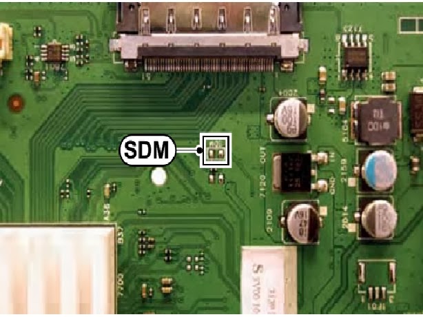
> Short one of the “Service” pads on the TV board during cold start Then press the mains button (remove the short after start-up).
Caution: When doing this, the service-technician must know exactly what he is doing, as it could damage the television set.
To activate digitalSDM:
> Press the following sequence on the RC transmitter: “062593” directly followed by the MENU button.
On Screen Menu
After activating SDM, the following items are displayed, with “SDM” in the upper right corner of the screen to indicate that the television is in Service Default Mode.
Menu items and explanation:
> xxxxx: Operating hours (in decimal).
> AAAAAAB-XX.YY: See paragraph Software
Identification, Version, and Clusterfor the SW name definition.
> ERR: Shows all errors detected since the last time the buffer was erased in format <xxx> <xxx> <xxx> <xxx> <xxx> (five errors possible).
> OP: Used to read-out the option bytes. Ten codes (in two rows) are possible.
How to Navigate
As this mode is read only, there is not much to navigate. To switch to other modes, use one of the following methods:
> Command MENU from the user remote will enter the normal user menu (brightness, contrast, color, etc...) with “SDM” OSD remaining, and pressing MENU key again will return to the last status of SDM again.
> To prevent the OSD from interfering with measurements in SDM, command “OSD” or “i+” (“STATUS” or “INFO” for NAFTA and LATAM) from the user remote will toggle the OSD “on/off” with “SDM” OSD remaining always “on”.
# Press the following key sequence on the remote control transmitter: “062596” directly followed by the INFO[i+]/OK button to switch to SAM (do not allow the display to time out between entries while keying the sequence).
How to Exit
Switch the set to Stand-by by
> pressing the standby button on the remote control transmitter or on the television set, or
> via a standard RC-transmitter by keying the “00” sequence. If you switch the television set “off” by removing the mains (i.e., unplugging the television), the television set will remain in SDM when mains is re-applied, and the error buffer is not cleared. The error buffer will only be cleared when the “clear” command is used in the SAM menu.
Note: If the TV is switched “off” by a power interrupt while in SDM, the TV will show up in the last status of SDM menu as soon as the power is supplied again. The error buffer will not be cleared.
In case the set is accidentally in Factory mode (with an “F” displayed on the screen), pressing and holding “VOL-“ button for 5 seconds and then followed by pressing and holding the “CH-” button for another 5 seconds should exit the Factory mode.
Service Alignment Mode (SAM)
Purpose
> To change option settings.
> To display / clear the error code buffer.
> To perform alignments.
Specifications
> Operation hours counter (maximum five digits displayed).
> Software version, error codes, and option settings display.
> Error buffer clearing.
> Option settings.
> Software alignments (White Tone).
> NVM Editor.
> Set screen mode to full screen (all content is visible).
> Set Smart Picture to “Game”.
How to Activate
To activate SAM, use one of the following methods:
> Press the following key sequence on the remote control transmitter: “062596” directly followed by the INFO[i+] /OK button. Do not allow the display to time out between entries while keying the sequence.
> Or via ComPair.
After entering SAM, the following items are displayed, with “SAM” in the upper right corner of the screen to indicate that the television is in Service Alignment Mode.
System Information.
> Op Hour:This represents the life timer. The timer counts normal operation hours, but does not count Stand-by hours.
>MAIN SW ID
> ERR:Shows all errors detected since the last time the buffer was erased. Five errors possible.
> OP1/OP2:Used to read-out the option bytes. Ten codes are possible.
Tuner.
> AGC Adjustment:
Store:To store the data.
# Clear. Erases the contents of the error buffer. Select this menu item and press the MENU RIGHT key on the remote control. The content of the error buffer is cleared.
#Options.To set the option bits.
# RGB Align.To align the White Tone.
# NVM Editor.To change the NVM data in the television set.
# Upload to USB.
# Download from USB.
# Initialise NVM.To initialize a (corrupted) NVM. Be careful, this will erase all settings!
# Auto ADC.
# EDID Write Enable.Enables EDID writing (not applicable to Berlinale sets).
# Service Data.Virtual Key board for character input entry.
How to Navigate
> In the SAM menu, select menu items with the UP/DOWN keys on the remote control transmitter. The selected item will be indicated. When not all menu items fit on the screen, use the UP/DOWN keys to display the next / previous menu items.
> With the LEFT/RIGHT keys, it is possible to: – Activate the selected menu item. – Change the value of the selected menu item. – Activate the selected sub menu.
> When you press the MENU button twice while in top level SAM, the set will switch to the normal user menu (with the SAM mode still active in the background). To return to the SAM menu press the MENU button.
> The “INFO[i+]/OK” key from the user remote will toggle the OSD “on/off” with “SAM” OSD remaining always “on”.
> Press the following key sequence on the remote control transmitter: “062596” directly followed by the MENU button to switch to SDM (do not allow the display to time out between entries while keying the sequence).
How to Store SAM Settings
To store the settings changed in SAM mode (except the OPTIONS and RGB ALIGN settings), leave the top level SAM menu by using the POWER button on the remote control transmitter or the television set. The mentioned exceptions must be stored separately via the STORE button.
How to Exit
Switch the set to STANDBY by pressing the mains button on the remote control transmitter or the television set, or by keying-in the “00” sequence on a standard RC-transmitter.
Note: When the TV is switched “off” by a power interrupt while in SAM, the TV will show up in “normal operation mode” as soon as the power is supplied again. The error buffer will not be cleared.
> In case the set is in Factory mode by accident (with “F” displayed on screen), pressing and holding “VOL-“ button for 5 seconds and then followed by pressing and holding the “CH-” button for another 5 seconds should exit the Factory mode.
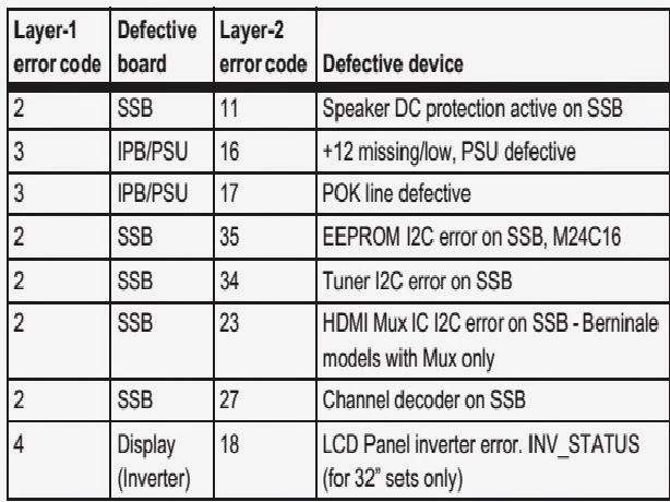
Error Codes
Error codes are required to indicate failures in the TV set. In principle a unique error code is available for every:
> Activated (SW) protection.
> Failing I2C device.
> General I2C error. The last five errors, stored in the NVM, are shown in the Service menu’s. This is called the error buffer. The error code buffer contains all errors detected since the last time the buffer was erased. The buffer is written from left to right. When an error occurs that is not yet in the error code buffer, it is displayed at the left side and all other errors shift one position to the right. An error will be added to the buffer if this error differs from any error in the buffer. The last found error is displayed on the left. An error with a designated error code neverleads to a deadlock situation. It must always be diagnosable (e.g. error buffer via OSD or blinking LED or via ComPair).In case a failure identified by an error code automatically results in other error codes (cause and effect), only the error code of the MAIN failure is displayed.How to Read the Error Buffer
You can read the error buffer in three ways:
> On screen via the SAM/SDM/CSM (if you have a picture).
Example:
#– ERROR: 0 0 0 0 0: No errors detected
# ERROR: 6 0 0 0 0: Error code 6 is the last and only detected error
# ERROR: 9 6 0 0 0: Error code 6 was detected first and error code 9 is the last detected (newest) error
# Via the blinking LED procedure (when you have no picture).
Error codes
The “layer 1” error codes are pointing to the defective board. They are triggered by LED blinking when CSM is activated. In the LC10 platform, only two boards are present: the SSB and the PSU/IPB, meaning only the following layer 1 errors are defined:
> 2: SSB
> 3: IPB/PSU
> 4: Display
How to Clear the Error Buffer
The error code buffer is cleared in the following cases:
> By using the CLEAR command in the SAM menu:
> By using the following key sequence on the remote control transmitter: “062599” directly followed by the OK button.
> If the contents of the error buffer have not changed for 50 hours, the error buffer resets automatically.
Note: If you exit SAM by disconnecting the mains from the television set, the error buffer is not reset..ERROR CODE TABLEThe Blinking LED Procedure
The software is capable of identifying different kinds of errors. Because it is possible that more than one error can occur over time, an error buffer is available, which is capable of storing the last five errors that occurred. This is useful if the OSD is not working properly. Errors can also be displayed by the blinking LED procedure. The method is to repeatedly let the front LED pulse with as many pulses as the error code number, followed by a period of 1.5 seconds in which the LED is “off”. Then this sequence is repeated.
Example (1): error code 4 will result in four times the sequence LED “on” for 0.25 seconds / LED “off” for 0.25 seconds. After this sequence, the LED will be “off” for 1.5 Sconds. Any RC command terminates the sequence. Error code LED blinking is in red color.
Example (2): the content of the error buffer is “129600”
After entering SDM, the following occurs:
> 1 long blink of 5 seconds to start the sequence,
> 12 short blinks followed by a pause of 1.5 seconds,
> 9 short blinks followed by a pause of 1.5 seconds,
> 6 short blinks followed by a pause of 1.5 seconds,
> 1 long blink of 1.5 seconds to finish the sequence,
> The sequence starts again with 12 short blinks.
Displaying the Entire Error Buffer
Additionally, the entire error buffer is displayed when Service Mode “SDM” is entered.


.jpg)