Quantcast
Channel: Electro help
Viewing all 2033 articles
Browse latest View live

NO VIDEO [TUNER DTV]-NO VIDEO[CVBS]-NO VIDEO[COMPONENT] - SAMSUNG LED LCD TV - UE***** SERIES

$
0
0

NO VIDEO [TUER DTV]
CLICK ON THE PICTURES TO ZOOM IN
NO VIDEO - VIDEO[CBVS]
NO VIDEO[COMPONENT]


NO SOUND - SAMSUNG UE***** SERIES LED LCD TVs - UE32_UE37_UE40_UE46_UE32C4000 – NO AUDIO (No Sound)

$
0
0

NO SOUND [Picture OK]
Click on the pictures to Zoom In

ERROR CODES - DETAILS - PHILIPS 40PFL6606 - LED LCD TV

$
0
0

ERROR CODES
  The error code buffer contains all detected errors since the last time the buffer was erased. The buffer is written from left to right, new errors are logged at the left side, and all other errors shift one position to the right.  When an error occurs, it is added to the list of errors, provided the list is not full. When an error occurs and the error buffer is full, then the new error is not added, and the error buffer stays intact (history is maintained).  To prevent that an occasional error stays in the list forever, the error is removed from the list after more than 50 hrs. of operation.  When multiple errors occur (errors occurred within a short time span), there is a high probability that there is some relation between them.
• If no errors are there, the LED should not blink at all in CSM or SDM. No spacer must be displayed as well.
• There is a simple blinking LED procedure for board level repair (home repair) so called LAYER 1 errors next to the existing errors which are LAYER 2 errors.
– LAYER 1 errors are one digit errors.
– LAYER 2 errors are 2 digit errors.
In protection mode.
– From consumer mode: LAYER 1.
– From SDM mode: LAYER 2.
Fatal errors, if I2C bus is blocked and the set reboots, CSM and SAM are not selectable.
– From consumer mode: LAYER 1.
– From SDM mode: LAYER 2.
In CSM mode.
– When entering CSM: error LAYER 1will be displayed by blinking LED. Only the latest error is shown.
In SDM mode.
– When SDM is entered via Remote Control code or the hardware pins, LAYER 2is displayed via blinking LED.
Error display on screen.
– In CSM no error codes are displayed on screen.
– In SAM the complete error list is shown.
Basically there are three kinds of errors:
• Errors detected by the Stand-by software which lead to protection.These errors will always lead to protection and an automatic start of the blinking LED LAYER 1 error.
• Errors detected by the Stand-by software which not lead to protection.In this case the front LED should blink the involved error.  Note that it can take up several minutes before the TV starts blinking the error (e.g. LAYER 1 error = 2, LAYER 2 error = 15 or 53).
• Errors detected by main software (MIPS). In this case the error will be logged into the error buffer and can be read out via ComPair, via blinking LED method LAYER 1-2 error, or in case picture is visible, via SAM.
How to Read the Error Buffer
Use one of the following methods:
• On screen via the SAM (only when a picture is visible).
E.g.:
– 00 00 00 00 00: No errors detected
23 00 00 00 00: Error code 23 is the last and only detected error.
3723 00 00 00: Error code 23 was first detected and error code 37 is the last detected error.
– Note that no protection errors can be logged in the error buffer.
How to Clear the Error Buffer
Use one of the following methods:
• By activation of the “RESET ERROR BUFFER” command in the SAM menu.
• If the content of the error buffer has not changed for 50+ hours, it resets automatically.
Error Buffer
In case of non-intermittent faults, clear the error buffer before starting to repair (beforeclearing the buffer, write down the content, as this history can give significant information). This to ensure that old error codes are no longer present. If possible, check the entire contents of the error buffer. In some situations, an error code is only the result of another error code and not the actual cause (e.g. a fault in the protection detection circuitry can also lead to a protection). There are several mechanisms of error detection:
• Via error bits in the status registers of ICs.
• Via polling on I/O pins going to the stand-by processor.
• Via sensing of analog values on the stand-by processor or the PNX8550.
• Via a “not acknowledge” of an I2C communication.
Take notice that some errors need several minutes before they start blinking or before they will be logged. So in case of problems wait 2 minutes from start-up onward, and then check if the front LED is blinking or if an error is logged.
ERROR CODE TABLE
Click on the Table to Zoom In
Rebooting.
When a TV is constantly rebooting due to internal problems, most of the time no errors will be logged or blinked. This rebooting can be recognized via a ComPair interface and Hyperterminal. It’s shown that the loggings which are generated by the main software keep continuing. In this case diagnose has to be done via compare.
Error 13 (I2C bus 3, SSB bus blocked). Current situation:
when this error occurs, the TV will constantly reboot due to the blocked bus. The best way for further diagnosis here, is to use ComPair.
Error 14 (I2C bus 2, TV set bus blocked). Current situation: when this error occurs, the TV will constantly reboot due to the blocked bus. The best way for further
diagnosis here, is to use ComPair.
Error 18 (I2C bus 4, Tuner bus blocked).
 In case this bus is blocked, short the “SDM” solder paths on the SSB during startup, LAYER error 2 = 18 will be blinked.
Error 15 (PNX8550 doesn’t boot). Indicates that the main processor was not able to read his bootscript. This error will point to a hardware problem around the PNX8550 (supplies not OK, PNX 8550 completely dead, I2C link between PNX and Stand-by Processor broken, etc...).   When error 15 occurs it is also possible that I2C1 bus is blocked (NVM). I2C1 can be indicated in the schematics as follows: SCL-UP-MIPS, SDA-UP-MIPS. Other root causes for this error can be due to hardware problems regarding the DDR’s and the bootscript reading from the PNX8550.
Error 16 (12V). This voltage is made in the power supplyand results in protection (LAYER 1 error = 3) in case of absence. When SDM is activated we see blinking LED LAYER 2 error = 16.
Error 17 (Invertor or Display Supply). Here the status of the “Power OK” is checked by software, no protection will occur during failure of the invertor or display supply (no picture), only error logging. LED blinking of LAYER 1 error = 3 in CSM, in SDM this gives LAYER 2 error = 17.
Error 21 (PNX51X0). When there is no I2C communication towards the PNX51X0 after start-up, LAYER 2 error = 21 will be logged and displayed via the blinking LED
procedure if SDM is switched on. This device is located on the 200 Hz panel from the display.
Error 23 (HDMI). When there is no I2C communication towards the HDMI mux after start-up, LAYER 2 error = 23 will be logged and displayed via the blinking LED procedure if SDM is switched on.
Error 24 (I2C switch). When there is no I2C communication towards the I2C switch, LAYER 2 error = 24 will be logged and displayed via the blinking LED procedure when SDM is switched on. Remark: this only works for TV sets with an I2C controlled screen included.
Error 28 (Channel dec DVB-S). When there is no I2C communication towards the DVB-S channel decoder, LAYER 2 error = 28 will be logged and displayed via the
blinking LED procedure if SDM is switched on.
Error 31 (Lnb controller). When there is no I2C communication towards this device, LAYER 2 error = 31 will be logged and displayed via the blinking LED procedure if SDM is activated.
Error 34 (Tuner). When there is no I2C communication towards the tuner during start-up, LAYER 2 error = 34 will be logged and displayed via the blinking LED procedure when SDM is switched on.
Error 35 (main NVM). When there is no I2C communication towards the main NVM during start-up, LAYER 2 error = 35 will be displayed via the blinking LED
procedure when SDM is switched “on”. All service modes (CSM, SAM and SDM) are accessible during this failure, observed in the Uart logging as follows: "<< ERRO >>> PFPOW_.C: First Error (id19, Layer_1= 2 Layer_= 35)".
Error 36 (Tuner DVB-S). When there is no I2C communication towards the DVB-S tuner during start-up, LAYER 2 error = 36 will be logged and displayed via the
blinking LED procedure when SDM is switched “on”.
Error 42 (Temp sensor). Only applicable for TV sets equipped with temperature devices.
Error 53. This error will indicate that the PNX8550 has read his bootscript (when this would have failed, error 15 would blink) but initialization was never completed because of hardware problems (NAND flash, ...) or software initialization problems. Possible cause could be that there is no valid software loaded (try to upgrade to the latest main software version). Note that it can take a few minutes before the TV starts blinking LAYER 1 error = 2 or in SDM, LAYER 2 error = 53.
Error 64. Only applicable for TV sets with an I2C controlled screen.

REPAIR TIPS - PHILIPS LED LCD TV - 40PFL-6606D - LED BLINKING PROCEDURES & OTHERS

$
0
0

LED BLINKING
The blinking LED procedure can be split up into two situations:
• Blinking LED procedure LAYER 1 error.In this case the error is automatically blinked when the TV is put in CSM. This will be only one digit error, namely the one that is referring to the defective board which causes the failure of the TV. This approach will especially be used for home repair and call centres. The aim here is to have service diagnosis from a distance.
• Blinking LED procedure LAYER 2 error.Via this procedure, the contents of the error buffer can be made visible via the front LED. In this case the error contains
2 digits and will be displayed when SDM (hardware pins) is activated. This is especially useful for fault finding and gives more details regarding the failure of the defective board.
Important remark:
For an empty error buffer, the LED should not blink at all in CSM or SDM. No spacer will be displayed.
When one of the blinking LED procedures is activated, the front LED will show (blink) the contents of the error buffer. Error codes greater then 10 are shown as follows:
1. “n” long blinks (where “n” = 1 to 9) indicating decimal digit
2. A pause of 1.5 s
3. “n” short blinks (where “n”= 1 to 9)
4. A pause of approximately 3 s,
5. When all the error codes are displayed, the sequence finishes with a LED blink of 3 s (spacer).
6. The sequence starts again.
Example: Error 12 8 6 0 0.
After activation of the SDM, the front LED will show:
One long blink of 750 ms (which is an indication of the decimal digit) followed by a pause of 1.5
Two short blinks of 250 ms followed by a pause of 3 s
Eight short blinks followed by a pause of 3 s
Six short blinks followed by a pause of 3 s
One long blink of 3 s to finish the sequence (spacer).
The sequence starts again.
Blinking LED Procedure
Activate the CSM. 
The blinking front LED will show only the latest layer 1 error, this works in “normal operation” mode or automatically when the error/protection is monitored by the Stand-by processor.  In case no picture is shown and there is no LED blinking.
Activate the SDM. 
The blinking front LED will show the entire content of the LAYER 2 error buffer, this works in “normal operation” mode or when SDM (via hardware pins) is activated when the tv set is in protection.
Software Protections
Most of the protections and errors use either the stand-by microprocessor or the MIPS controller as detection device. Since in these cases, checking of observers, polling of ADCs, and filtering of input values are all heavily software based, these protections are referred to as software protections.  There are several types of software related protections, solving a variety of fault conditions:
• Related to supplies:presence of the +5V, +3V3 and 1V2 needs to be measured, no protection triggered here.
• Protections related to breakdown of the safety check mechanism.E.g. since the protection detections are done by means of software, failing of the software will have to initiate a protection mode since safety cannot be guaranteed any more.
Remark on the Supply Errors
The detection of a supply dip or supply loss during the normal playing of the set does not lead to a protection, but to a cold reboot of the set. If the supply is still missing after the reboot, the TV will go to protection.
Protections during Start-up
During TV start-up, some voltages and IC observers are actively monitored to be able to optimise the start-up speed, and to assure good operation of all components. If these monitors do not respond in a defined way, this indicates a malfunction of the system and leads to a protection. As the observers are only used during start-up.
Hardware Protections
The only real hardware protection in this chassis appears in case of an audio problem e.g. DC voltage on the speakers. This protection will only affect the Class D audio amplifier  and puts the amplifier in a continuous burst mode (cyclus approximately 2 seconds).
Repair Tip
• There still will be a picture available but no sound. While the Class D amplifier tries to start-up again, the cone of the loudspeakers will move slowly in one or the other direction until the initial failure shuts the amplifier down, this cyclus starts over and over again. The headphone amplifier will also behaves similar.
Fault Finding and Repair Tips
Ambilight
Due to degeneration process of the LED’s fitted on the ambi module, there can be a difference in the color and/or light output of the spare ambilight modules in comparison with the originals ones contained in the TV set. Via SAM => alignments => ambilight, the spare module can be adjusted.
Audio Amplifier
The Class D-IC 7D10 has a powerpad for cooling. When the IC is replaced it must be ensured that the powerpad is very well pushed to the PWB while the solder is still liquid. This is needed to insure that the cooling is guaranteed, otherwise the Class DIC could break down in short time.
AV PIP
To check the AV PIP board (if present) functionality, a dedicated testpattern can be invoked as follows: select the “multiview” icon in the User Interface and press the “OK” button. Apply for the main picture an extended source, e.g. HDMI input. Proceed by entering CSM (push ‘123654’ on the remote control) and press the yellow button. A colored testpattern should appear now, generated by the AV PIP board (this can take a few seconds).
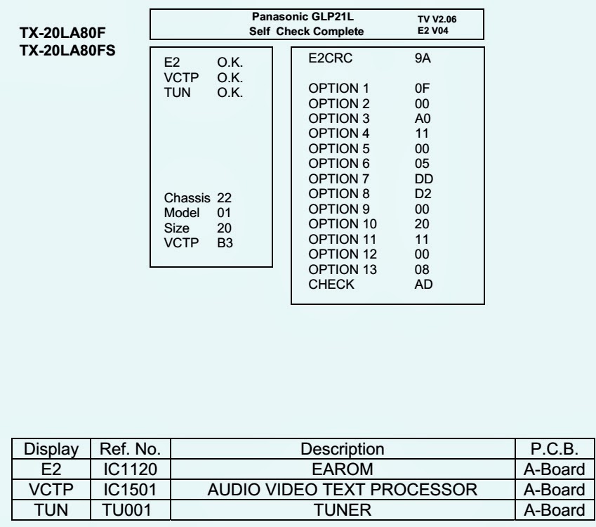
CSM
When CSM is activated and there is a USB stick connected to the TV, the software will dump the complete CSM content to the USB stick. The file (Csm.txt) will be saved in the root of the USB stick. If this mechanism works it can be concluded that a large part of the operating system is already working (MIPS, USB...)
 DC/DC Converter
The basic board power supply consists of 4 DC/DC converters and 5 linear stabilizers. All DC/DC converters have +12V input voltage and deliver:
• +1V1 supply voltage (1.15V nominal), for the core voltage of PNX855xx, stabilized close to the point of load; SENSE+1V1 signal provides the DC-DC converter the
needed feedback to achieve this.
• +1V8 supply voltage, for the DDR2 memories and DDR2 interface of PNX855xx.
• +3V3 supply voltage (3.30V nominal), overall 3.3 V for onboard IC’s, for non-5000 series SSB diversities only.
• +5V (5.15V nominal) for USB, WIFI and Conditional Access Module and +5V5-TUN for +5V-TUN tuner stabilizer.
The linear stabilizers are providing:
• +1V2 supply voltage (1.2V nominal), stabilized close to PNX855xx device, for various other internal blocks of PNX855xx; SENSE+1V2 signal provides the needed
feedback to achieve this.
• +2V5 supply voltage (2.5V nominal) for LVDS interface and various other internal blocks of PNX855xx; for 5000 series SSB diversities the stabilizer is 7UD2 while for the other diversities 7UC0 is used.
• +3V3 supply voltage (3V3 nominal) for 5000 series SSB diversities, provided by 7UD3; in this case the 12V to 3V3 DC-DC converter is not present.
• +5V-TUN supply voltage (5V nominal) for tuner and IF amplifier.  +3V3-STANDY (3V3 nominal) is the permanent voltage, supplying the Stand-by microprocessor inside PNX855xx.  Supply voltage +1V1 is started immediately when +12V voltage becomes available (+12V is enabled by STANDBY signal when "low"). Supply voltages +3V3, +2V5, +1V8, +1V2 and +5V-TUN are switched "on" by signal ENABLE-3V3 when "low", provided that +12V (detected via 7U40 and 7U41) is present.
+12V is considered OK (=> DETECT2 signal becomes "high", +12V to +1V8, +12V to +3V3, +12V to +5V DC-DC converter can be started up) if it rises above 10V and doesn’t drop below 9V5. A small delay of a few milliseconds is introduced between the start-up of 12V to +1V8 DC-DC converter and the two other DC-DC converters via 7U48 and associated components.
Description DVB-S2:
• LNB-RF1 (0V = disabled, 14V or 18V in normal operation) LNB supply generated via the second conversion channel of 7T03 followed by 7T50 LNB supply control IC. It provides supply voltage that feeds the outdoor satellite reception equipment.
• +3V3-DVBS (3V3 nominal), +2V5-DVBS (2V5 nominal) and +1V-DVBS (1.03V nominal) power supply for the silicon tuner and channel decoder. +1V-DVBS is generated via a 5V to 1V DC-DC converter and is stabilized at the point of load (channel decoder) by means of feedback signal SENSE+1V0-DVBS. +3V3-DVBS and +2V5-DVBS are generated via linear stabilizers from +5V-DVBS that by itself is generated via the first conversion channel of 7T03.
At start-up, +24V becomes available when STANDBY signal is "low" (together with +12V for the basic board), when +3V3 from the basic board is present the two DC-DC converters channels inside 7T03 are activated. Initially only the 24V to 5V converter (channel 1 of 7T03 generating +5V-DVBS) will effectively work, while +V-LNB is held at a level around 11V7 via diode 6T55. After 7T05 is initialized, the second channel of 7T03 will start and generates a voltage higher then LNB-RF1 with 0V8. +5VDVBS start-up will imply +3V3-DVBS start-up, with a small delay of a few milliseconds => +2V5-DVBS and +1V-DVBS will be enabled.  If +24V drops below +15V level then the DVB-S2 supply will stop, even if +3V3 is still present.
Debugging
The best way to find a failure in the DC/DC converters is to check their start-up sequence at power “on” via the mains cord, presuming that the stand-by microprocessor and the external supply are operational. Take STANDBY signal "high"-to-"low" transition as time reference.  When +12V becomes available (maximum 1 second after STANDBY signal goes "low") then +1V1 is started immediately. After ENABLE-3V3 goes "low", all the other supply voltages should rise within a few milliseconds.
Tips
• Behavior comparison with a reference TV550 platform can be a fast way to locate failures.
• If +12V stays "low", check the integrity of fuse 1U40.
• Check the integrity (at least no short circuit between drain and source) of the power MOS-FETs before starting up the platform in SDM, otherwise many components might be damaged. Using a ohmmeter can detect short circuits between any power rail and ground or between +12V and any other power rail.
• Short circuit at the output of an integrated linear stabilizer (7UC0, 7UD2 or 7UD3) will heat up this device strongly.
• Switching frequencies should be 500 kHz ...600 kHz for 12 V to 1.1 V and 12 V to 1.8 V DC-DC converters, 900 kHz for 12 V to 3.3 V and 12 V to 5 V DC-DC
converters. The DVB-S2 supply 24 V to 5 V and 24 V to +V LNB DC-DC converters operates at 300 kHz while for 5 V to 1.1 V DC-DC converter 900 kHz is used.
Exit “Factory Mode”
When an “F” is displayed in the screen’s right corner, this means the set is in “Factory” mode, and it normally happens after a new SSB is mounted. To exit this mode, push the “VOLUME minus” button on the TV’s local keyboard for 10 seconds (this disables the continuous mode).  Then push the “SOURCE” button for 10 seconds until the “F” disappears from the screen.
Logging
When something is wrong with the TV set (f.i. the set is rebooting) you can check for more information via the logging in Hyperterminal. The Hyperterminal is available in every Windows application via Programs, Accessories, Communications, Hyperterminal. Connect a “ComPair UART”-cable (3138 188 75051) from the service connector in the TV to the “multi function” jack at the front of ComPair II box.
Required settings in ComPair before starting to log:
- Start up the ComPair application.
- Select the correct database (open file “Q55X.X”, this will set the ComPair interface in the appropriate mode).
- Close ComPair
After start-up of the Hyperterminal, fill in a name (f.i. “logging”) in the “Connection Description” box, then apply the following settings:
1. COMx
2. Bits per second = 115200
3. Data bits = 8
4. Parity = none
5. Stop bits = 1
6. Flow control = none
During the start-up of the TV set, the logging will be displayed. This is also the case during rebooting of the TV set (the same logging appears time after time). Also available in the logging is the “Display Option Code” (useful when there is no picture), look for item “DisplayRawNumber” in the beginning of the logging.
Tip: when there is no picture available during rebooting you are able to check for “error devices” in the logging (LAYER 2 error) which can be very helpful to determine the failure cause of the reboot. For protection state, there is no logging.
Description possible cases:
Uart loggings are displayed:
• When Uart loggings are coming out, the first conclusion we can make is that the TV set is starting up and communication with the flash RAM seems to be supported. The PNX855xx is able to read and write in the DRAMs.
• We can not yet conclude : Flash RAM and DRAMs are fully operational/reliable.There still can be errors in the data transfers, DRAM errors, read/write speed and timing control.
No Uart logging at all:
• In case there is no Uart logging coming out, check if the startup script can be send over the I2C bus (3 trials to startup) + power supplies are switched on and stable.
• No startup will end up in a blinking LED status : error LAYER 1 = “2”, error LAYER 2 = “53” (startup with SDM solder paths short).
• Error LAYER 2 = “15” (hardware cause) is more related to a supply issue while error LAYER 2 = “53” (software cause) refers more to boot issues.
Uart loggings reporting fault conditions, error messages, error codes, fatal errors:
• Failure messages should be checked and investigated. For instance fatal error on the PNX51x0: check startup of the back-end processor, supplies..reset, I2C bus. => error mentioned in the logging as: *51x0 failed to start by itself*.
• Some failures are indicated by error codes in the logging, check with error codes table (see Table “5-2 Error code overview”).e.g. => <<ERROR>>>PLFPOW_MERR.C : First Error (id=10,Layer_1=2,Layer_2=23).
• I2C bus error mentioned as e.g.: “ I2C bus 4 blocked”.
• Not all failures or error messages should be interpreted as fault.For instance root cause can be due to wrong option codes settings => e.g. “DVBS2Suppoprted : False/True.  In the Uart log startup script we can observe and check the enabled loaded option codes.  Defective sectors (bad blocks) in the Nand Flash can also be reported in the logging.
Startup in the SW upgrade application and observe the Uart logging:
Starting up the TV set in the Manual Software Upgrade mode will show access to USB, meant to copy software content from USB to the DRAM.Progress is shown in the logging as follows:
“cosupgstdcmds_mcmdwritepart: Programming 102400 bytes, 40505344 of 40607744 bytes programmed”.
Startup in Jett Mode:
Check Uart logging in Jet mode mentioned as : “JETT UART READY”. Uart logging changing preset:
=> COMMAND: calling DFB source = RC6, system=0, key = 4”.
Loudspeakers
Make sure that the volume is set to minimum during disconnecting the speakers in the ON-state of the TV. The audio amplifier can be damaged by disconnecting the speakers during ON-state of the set.
PSL
In case of no picture when CSM (test pattern) is activated and backlight doesn’t light up, it’s recommended first to check the inverter on the PSL + wiring (LAYER 2 error = 17 is displayed in SDM).
Tuner
Attention: In case the tuner is replaced, always check the tuner options.
Display option code
Attention: In case the SSB is replaced, always check the display option code in SAM, even when picture is available. Performance with the incorrect display option code can lead to unwanted side-effects for certain conditions.
New in this chassis:
While in the download application (start up in TV mode + “OK” button pressed), the display option code can be changed via 062598 HOME XXX special SAM command (XXX=display option in 3 digits).

HOW TO ENTER CUSTOMER SERVICE MODE [CSM] - PHILIPS 40PFL6606D - LCD TVs

$
0
0

CUSTOMER SERVICE MODE
Purpose
   When a customer is having problems with his TV-set, he can call his dealer or the Customer Helpdesk. The service technician can then ask the customer to activate the CSM, in order to identify the status of the set. Now, the service technician can judge the severity of the complaint. In many cases, he can advise the customer how to solve the problem, or he can decide if it is necessary to visit the customer.  The CSM is a read only mode; therefore, modifications in this mode are not possible.
   When in this chassis CSM is activated, a test pattern will be  displayed during 5 seconds (1 second Blue, 1 second Green and 1 second Red, then again 1 second Blue and 1 second Green). This test pattern is generated by the PNX51X0 (located on the 200Hz board as part of the display). So if this test pattern is shown, it could be determined that the back end video chain (PNX51X0 and display) is working.  For TV sets without the PNX51X0 inside, every menu from CSM will be used as check for the back end chain video.
   When CSM is activated andthere is a USB stick connected to the TV set, the software will dump the CSM content to the USB stick. The file (CSM_model number_serial number.txt) will be saved in the root of the USB stick. This info can be handy if no information is displayed.
When in CSM mode (and a USB stick connected), pressing “OK” will create an extended CSM dumpfile on the USB stick. This file (Extended_CSM_model number_serial number.txt) contains:
• The normal CSM dump information,
• All items (from SAM “load to USB”, but in readable format),
• Operating hours,
• Error codes,
• SW/HW event logs.
   To have fast feedback from the field, a flash dump can be requested by development. When in CSM, push the “red” button and key in serial digits ‘2679’ (same keys to form the word ‘COPY’ with a cellphone). A file “Dump_model number_serial number.bin” will be written on the connected USB device. This can take 1/2 minute, depending on the quantity of data that needs to be dumped.  Also when CSM is activated, the LAYER 1 error is displayed via blinking LED.
How to Activate CSM
Key in the code “123654” via the standard RC transmitter.  Note: Activation of the CSM is only possible if there is no (user) menu on the screen.
How to Navigate
By means of the “CURSOR-DOWN/UP” knob on the RC transmitter, can be navigated through the menus.
Contents of CSM
The contents are reduced to 3 pages: General, Software versions and Quality items. The group names itself are not shown anywhere in the CSM menu.
General
• Set Type.This information is very helpful for a helpdesk/workshop as reference for further diagnosis. In this way, it is not necessary for the customer to look at the rear of the TV-set. Note that if an NVM is replaced or is initialized after corruption, this set type has to be re-written to NVM. ComPair will foresee in a possibility to do this. The update can also be done via the NVM editor available in SAM.
• Production Code.Displays the production code (the serial number) of the TV. Note that if an NVM is replaced or is initialized after corruption, this production code has to be re-written to NVM. ComPair will foresee in a possibility to do this. The update can also be done via the NVM editor available in SAM.
• Installed date.Indicates the date of the first installation of the TV. This date is acquired via time extraction.
• Options 1.Gives the option codes of option group 1 as set in SAM (Service Alignment Mode).
• Options 2.Gives the option codes of option group 2 as set in SAM (Service Alignment Mode).
• 12NC SSB.Gives an identification of the SSB as stored in NVM. Note that if an NVM is replaced or is initialized after corruption, this identification number has to be re-written to NVM. ComPair will foresee in a possibility to do this. This identification number is the 12nc number of the SSB.
• 12NC display.Shows the 12NC of the display.
• 12NC supply.Shows the 12NC of the power supply.
• 12NC 200Hz board.Shows the 12NC of the 200Hz Panel (when present).
• 12NC AV PIP.Shows the 12NC of the AV PIP board (when present).
Software versions
• Current main SW.Displays the build-in main software version. In case of field problems related to software, software can be upgraded. As this software is consumer upgradeable, it will also be published on the Internet.  Example: Q55xx1.2.3.4
• Stand-by SW.Displays the build-in stand-by processor software version. Upgrading this software will be possible via ComPair or via USB.
• e-UM version.Displays the electronic user manual SWversion (12NC version number). Most significant number here is the last digit.
• AV PIP software.
• 3D dongle software version.
Quality items
• Signal quality.Bad / average /good (not for DVB-S).  • Ethernet MAC address. Displays the MAC address present in the SSB.
• Wireless MAC address.Displays the wireless MAC address to support the Wi-Fi functionality.
• BDS key.Indicates if the set is in the BDS status.
• CI module.Displays status if the common interface module is detected.
• CI + protected service.Yes/No.
• Event counter:
S : 000X 0000(number of software recoveries : SW EVENT-LOG #(reboots)
S : 0000 000X (number of software events : SW EVENTLOG #(events)
H : 000X 0000(number of hardware errors.
H : 0000 000X (number of hardware events : SW EVENTLOG #(events).
How to Exit CSM
Press “MENU” (or "HOME") / “Back” key on the RC-transmitter.

SDM [Service Default Mode] - HOW TO ENTER SDM - PHILIPS 40PFL6606D-LCD TVs

$
0
0

SERVICE DEFAULT MODE
How to Activate SDM
For this chassis there are two kinds of SDM: an analogue SDM and a digital SDM. Tuning will happen according Table.
Service Default mode (SDM) and Service Alignment Mode (SAM) offers several features for the service technician, while the Customer Service Mode (CSM) is used for communication between the call centre and the customer.
As most signals are digital, it will be difficult to measure waveforms with a standard oscilloscope. However, several key ICs are capable of generating test patterns, which can be controlled via ComPair. In this way it is possible to determine which part is defective.
Perform measurements under the following conditions:
• Service Default Mode.
• Video: Color bar signal.
• Audio: 3 kHz left, 1 kHz right.
This chassis also offers the option of using ComPair, a hardware interface between a computer and the TV chassis. It offers the abilities of structured troubleshooting, error code reading, and software version read-out for all chassis.
Note: For the new model range, a new remote control (RC) is used with some renamed buttons. This has an impact on the activation of the Service modes. For instance the old “MENU” button is now called “HOME” (or is indicated by a “house” icon).
Service Default Mode (SDM)
Purpose
• To create a pre-defined setting, to get the same measurement results as given in this manual.
• To override SW protections detected by stand-by processor and make the TV start up to the step just before protection (a sort of automatic stepwise start-up).
• To start the blinking LED procedure where only LAYER 2 errors are displayed.
• All picture settings at 50% (brightness, color, contrast).
• Sound volume at 25%.
SDM DEFAULT SETTINGS
Analogue SDM: use the standard RC-transmitter and key in the code “062596”, directly followed by the “MENU” (or “HOME”) button. [Note: It is possible that, together with the SDM, the main menu will appear. To switch it “off”, push the “MENU” (or "HOME") button again.  Analogue SDMcan also be activated by grounding for a moment the solder path on the SSB, with the indication “SDM”]
Digital SDM: use the standard RC-transmitter and key in the code “062593”, directly followed by the “MENU” (or "HOME") button. [Note: It is possible that, together with the SDM, the main menu will appear. To switch it “off”, push the “MENU” (or "HOME") button again.]
After activating this mode, “SDM” will appear in the upper right corner of the screen (when a picture is available).
How to Navigate
When the “MENU” (or “HOME”) button is pressed on the RC transmitter, the TV set will toggle between the SDM and the normal user menu.
How to Exit SDM
Use one of the following methods:
Switch the set to STAND-BY via the RC-transmitter.
Via a standard customer RC-transmitter: key in “00”-sequence.

BenQ - FP-767 - MONITOR - POWER SUPPLY [SMPS] - SCHEMATIV (Circuit Diagram)

$
0
0

POWER SUPPLY {SMPS} SCHEMATIC

CLICK ON THE SCHEMATIC TO ZOOM IN

CAIXA - LL600 - AMPLIFIER - SCHEMATIC DIAGRAM - (RC4558 – TIP41C – TIP42C)

$
0
0

SCHEMATIC


CLICK ON THE SCHEMATIC TO MAGNIFY


T-CON BOARD - CHECKS - LG47LG90 - LED LCD TV - PWB FUSE CHECKS

$
0
0

T-CON [TFT DRIVE] PWB
T-CON also drives the backlight LEDs in accordance to the necessary Light Source intensity according to the video content Contrast Ratio demands, (Local Dimming). Control signals to the Inverters are sent out.
CLICK ON THE PICTURES TO ZOOM IN
CN-301 & CN-804 - VOLTAGES
PWB - FUSE CHECKS
PWB REGULATOR & MAIN FUSE CHECKS
PWB _ DC to DC CONVERTER CHECKS
DC to DC CONVERTER [U7] CHECKS
CN-4 & CN-5 VOLTAGE CHECKS
CN-8 & CN-9 VOLTAGES AND RESISTANCES

LG 42LH50 - LCD TV - HOW TO ENTER SERVICE MODE - USB SOFTWARE UPDATE

$
0
0

SERVICE MODE
1) Turn the Set On
2) Simultaneously, Press and “Hold” the Menu Key on the Side Key pad and Press and “Hold” the Menu Key on the Remote approximately 5 seconds.
3) If Customer’s Menu appears, continue to hold until it disappears.
4) The Service Menu appear
If a Password is required to enter the Service Menu. Enter; [0000]
USB DOWNLOAD
1) Create an LG_DTV folder on the USB Flash Drive
2) Copy new software (xxx.epk) to "LG_DTV" folder. Make sure to have correct software file.
3) With TV turned on, insert USB flash drive.
4) You can see the message “TV Software Upgrade”
5) Cursor left and highlight "START" Button and push “Enter” button using the remote control.
6) You can see the download progress Bar.
7) Do not unplug until unit has automatically restarted.
8) When download is completed, you will see “COMPLETE”.
9) Your TV will be restarted automatically.
CAUTION:
Do not remove AC power or the USB Flash Drive. Do not turn off Power, during the upgrade process.

HOW TO REMOVE T-CON BOARD - LG42LH50 - EEFL - LCD TV

$
0
0

T-CON [LCD CONTROLLER BOARD] REMOVAL
The T-Con IC UC1 receives from the Main Board at CN1 12 Bit and CN2 12 Bit LVDS Signals (Video) which it processes into TFT Drive Signals. It delivers its output signals through connectors CN4 and CN5 to control the LCD Panel.  12V is supplied to the T-Con Board on connector CN1 from the Main Board (easily measured at fuse F1).
Diode LD1 is a boot up indicator and is helpful in troubleshooting as a quick indication of a loss of supply and or a Boot up problem. The main purpose of LD1 is to aid in the firing of the EEFL back-lights when room light is minimum.It helps to excite the selenium in the EEFL lamp which is highly sensitive to Blue light. Once this lamp fires, it helps to excite the others.
There is one regulator that creates 1.19V developed at pin 2 (Center Leg) of U11. U5 is a DC to DC converter IC which develops the Panels driver voltages. 16V, 3.3V, -5V and 26V.  These voltages can be read at the ribbon connector or attest points on the board.
CLICK ON THE PICTURES TO MAGNIFY 
Remove the 3 Screws in the T-CON shield and remove the shield.
The two screws shown in the picture below are for the Service Position.
They would have been removed when removing the shield.
Be sure to re-install them if servicing the T-CON PWB.
The two screws shown in the picture below are for the Service Position.  They would have been removed when removing the shield.  Be sure to re-install them if servicing the T-CON PWB.
Disconnect CN1, CN2, CN4 and CN5.
To remove the LVDS cables CN1 and CN2;
Press in on the two tabs and slowly rock the cable out of the connector. (Shown by the arrows in Figure).
To remove the flex cables to the TFT Panel, CN4 or CN5, place a soft thin object like a fingernail underneath the black locking tab and gently pull forward.
Flip the lock up and back from the flex cable.   Then the flex cable can be easily removed.

HOW TO CHECK POWER SUPPLY BOARD VOLTAGES - LG42LH50 - LCD TV

$
0
0

POWER SUPPLY [SMPS] BOARD
MAIN PWB TO SMPS P-201 TURN-ON CIRCUIT
CLICK ON THE PICTURES TO MAGNIFY 
POWER SUPPLY PWB _ LOW-VOLTAGE TEST
AC Should not be applied at any time while adding resistors or while unplugging connectors as damage tothe circuit PWB may occur.
a) The SMPS PWB “MUST” be producing STBY 5V on all of the pins 7, 8, 9 or 10 (5V).  If 5V Standby is not being generated, the SMPS PWB is defective and must be replaced. There is no need to continue with the next test.
(b) Unplug P2400 on the Main PWB.
TEST 1:
(1) Add a 100Ωresistor between (5V STBY) pin 7, 8, 9 or 10 and Pin 2 (PWR). Apply AC. This will turn on the power supply.
a) Check that the 24V and 12V power supplies are turned on,
• P201 (24V pins 17 and 18)
• P201 (12V pins 13 and 14)
(2) Remove AC power.
POWER SUPPLY PWB _ BACK-LIGHTS TEST
P2400 Connector disconnected from the MainPWB. Apply AC after adding jumper.
Continue if the 1st test was OK. Leave original resistor in place.
(3) Add another 100Ωresistor between (5V) pin 7, 8, 9 or 10 and Pin 20 (INV On).
(4) Apply AC Power. Simulating a Power and Backlight On command.
Backlights Normal:
a) If normal, the backlights should turn on. SMPS OK.
Backlights Abnormal:
a) Recheck all connections.
b) Confirm the INV On/Off line pulling up to at least 3V.
REMOVE AC POWER:
c) Check the connections to the Backlights.
DO NOTcheck these when AC is applied as they carry 1200V each.
Note, either of the connections are unplugged, the backlights will not light.
POWER SUPPLY CONNECTOR-P201 VOLTAGE & DIODE CHECK
ADIM Pin 21 Fixed and not used.
PDIM Pin 24 can vary according to type of signal being processed and the OSD Backlight setting.
0.6V 0% to 3.3V 100%. Output from the video processor IC100.

Diode Mode values taken with all Connectors Removed.

RP-29FC40P - LG CRT TV - POWER SUPPLY & HORIZONTAL-VERTICAL SCAN - SCHEMATIC

$
0
0

SMPS SCHEMATIC [STR-STR 6658B]

HORIZONTAL & VERTICAL SCAN OUTPUT
CLICK ON THE SCHEMATICS TO MAGNIFY

LG RP29FC40P Lafinion 72 – Lafinion 82W - VIDEO AMPLIFIER [CRT] & MICOM SCHEMATIC

$
0
0

CPT [Video Amplifier] Schematic TDA 6111Q – STK396-120
CLICK ON THE PICTURES TO MAGNIFY 
CPT - PWB
MICOM - PWB
MICOM - SCHEMATIC [M37280]

HBUSTER - HBTV32D03 – HBTV42D03HD (SSC9502S – FMV12N50E - STR-A6059H)SMPS [Power supply] - (Circuit Diagram)-[SCHEMATIC] - SERVICE MODE

$
0
0

POWER SUPPLY [SMPS] SCHEMATIC
CLICK ON THE SCHEMATICS TO ZOOM IN
Please take a printout of these schematic diagrams to view it better
STR A-6059H
PIN CONFIGURATIONS
SERVICE MODE
To enter service menu:  Press [Menu> 8> 8> 9> 3] by remote control buttons.
Follow the on-screen display for adjustments.


SONY HCD GT111/GT222/GT444/GT555 - SERVICE MODE-AGING-POWER AMPLIFIER SCHEMATIC

$
0
0

POWER SUPPLY - SCHEMATIC
POWER AMP
CLICK ON THE PICTURES TO MAGNIFY
UNLOCKING THE DISC TRAY
This is to prevent the theft of discs appliances demonstration in stores.
procedure:
1. Press [Power] to turn the unit.
2. Press the [CD] button to select this function.
3. For 5 seconds Press the [Stop] and [Eject] keys together.
4. The "UNLOCKED" message appears and the tray will released.

Note: When "LOCKED" appears, the lock will not be released to disconnect the unit from the [Power] button.
COLD RESET
The cold reset clears all data the device, including those saved in EEPROM, placing the device on your terms.  initials. Run it to return the unit to the consumer.
procedure:
1. Press the [Power] to turn the unit.
2. Press the [Stop] button, [ENTER] and [Power] simultaneously.
3. The message "COLD RESET" appears in the display. After that the display turns off and the device is reset.
METHOD OF DUTY CD
This mode allows you to freely move the sled motor. Use it when you want to clean the optical drive.
procedure:
1. Press the [Power] to turn the unit.
2. Press the [CD] button to select the function.
3. Press the [Stop] button, [METER MODE] and [OPEN / CLOSE] simultaneously.
4. Activates the service mode of the CD. The message "SERVICE MODE "appears on the fluorescent display.
5. The disc is stopped, press the [>>] button to move the the unit for the outermost track and [<<] to the innermost.  The "SLED OUT" or "SLED IN" message appears on the display.
6. To turn the laser, press the [>>|] button. The message "LD ON" or "OFF RB" on the display.
7. To exit this mode, press the [Power].
AGING MODE CD
This mode can be used to check the operation of the CD.  If an error occurs the aging mode will stop and the error status will be displayed. If no error occurs, the aging mode remains repeatedly.
procedure:
1. Press the [Power] to turn the unit.
2. Select the CD function.
3. Place three discs in the tray.
4. Press the [PLAY MODE] button repeatedly to control remote to select "ALL DISCS" mode and then press [REPEAT] repeatedly to select "REPEAT OFF".
5. Press the [Stop] button, [METER MODE] and [DISC SKIP /EX-CHANGE] simultaneously.
6. The aging mode starts.
7. To exit this mode press the [Power] to disconnect the ca-bod and power outlet.

LG RP-21FD10 RN-21FD10T - POWER SUPPLY - VIDEO OUTPUT - SCHEMATICS [CIRCUIT DIAGRAMS]

$
0
0

SMPS SCHEMATIC [F6654]
CLICK ON THE PICTURES TO ZOOM IN 
VIDEO OUTPUT / CRT BASE CARD
SERVICE MODE
With the SVC remote control.
Enter into adjustment mode by “INSTART” button.               
Adjust the item with CH UP / DN.                     
Adjust the data with VOL LEFT / RIGHT.

LG RU-42PX10/C RU-42PX11/H - TROUBLESHOOTING CHART - PLASMA TV - [No Power _ Protect Mode]

$
0
0

POWER BOARD TROUBLESHOOT 
CLICK ON THE PICTURES TO ZOOM IN 
Sony Power board structure & Pin Voltages
Sanken Power board structure & Pin Voltages
NO POWER
PROTECT MODE
After once shining, it does not discharge minutely from module
The Relay fails (The sound is audible “click”)
It is converted with the color where the front LED is red from green.

PANASONIC TX-20LA80F - TX-20LA80FS LCD TV - SERVICE MODE - SELF CHECK MODE - SMPS SCHEMATIC

$
0
0

SELF CHECK MODE
Self-check is used to automatically check the bus lines and hexadecimal code of the TV set. 
To enter Self-Check mode, keep pressing the STATUS [ i ] button on the remote control and press the down (-/v)button on the TV set. To exit Self Check, switch off the TV set at the power button.
If the CCU ports have been checked and found to be incorrect or not located then " - - " will appear in place of "O.K.".

SERVICE MODE
Set the Bass to maximum position, set the Treble to minimum position then keep pressing the INDEX button on the  remote control and press the down button (-/v) on the TV set, this will place the TV set into the Service Mode 1.
KEY COMMANDS
Press the RED / GREEN buttons to step up / down through the functions.
Press the YELLOW / BLUE buttons to alter the function values, to alter White Rasters use +/-buttons
Press the OK button after each adjustment has been made to store the required values.
To exit the Service Mode, press the "N" button.
SMPS SCHEMATIC [FULL]
Click on the pictures to Zoom In
Power Supply [Split]

SONY KDL-32EX715 - KDL-40EX715 - KDL-46EX715 - SMPS - [Power Supply] - Schematic (Circuit Diagram)

$
0
0

SMPS - SCHEMATIC 
SPLITs
CLICK ON THE SCHEMATICS TO ZOOM IN 

Viewing all 2033 articles
Browse latest View live