Quantcast
Channel: Electro help
Viewing all 2033 articles
Browse latest View live

SERVICE MODE AND ADJUSTMENTS - HAIER 21F7A - MEMOREX MT2024SM

$
0
0

SERVICE MODE
Specific operation: use remote controller
  • Press “MUTE”--> “CALL” --> “-\--“ --> “CALL” -->UTE”  buttons in sequence to enter into factory mode. 
  • Press [Program+] / [Program-] to select items and press [VOLUME+] / [VOLUME-] key , to  make data adjustment of  corresponding factory menus.
  • Press “EXIT” key to exit factory mode.
Geometrical adjustment: Receive PAL standard complete pattern signal.
Adjustment steps:
a)  Adjust VSL, to the center horizontal line just appears from half  bottom shadow .
b)  Adjust VAM, to get 92% of  vertical picture contents would be displayed on CRT .
c)  Adjust VSH, the center horizontal line corresponds to CRT vertical center.
d)  Adjust SCL, to the linearity of  P card  field is in proper condition.
e)  Adjust HSH, to get the picture horizontal center correspond to CRT horizontal center.
Receive NTSC signal and repeat above adjustment.
AGC  Adjustment
Receive 60dBμ (1mV) VH color bar pattern signal.
Select TOP item.
Adjust value, to noise reduce gradually and just disappeared point.
CRT cut off and white balance adjustment
a)  CRT cut off  adjustment
1.  Select item VG2B, then adjust value to 32.
2.  PRESS “0” key , when  the screen  shows”VG2” adjust  the SCREEN control on Fly back  transformer [LOT] to make the screen show alternating f lashing characters of “INSIDE HIGH  INSIDE LOW”.
b)  White balance adjustment
1.  Receive a Black and White pattern.
2.  Adjust WRP , WRG , WRB items to get color temperature 9300K ±3 JND.
IC VOLTAGES
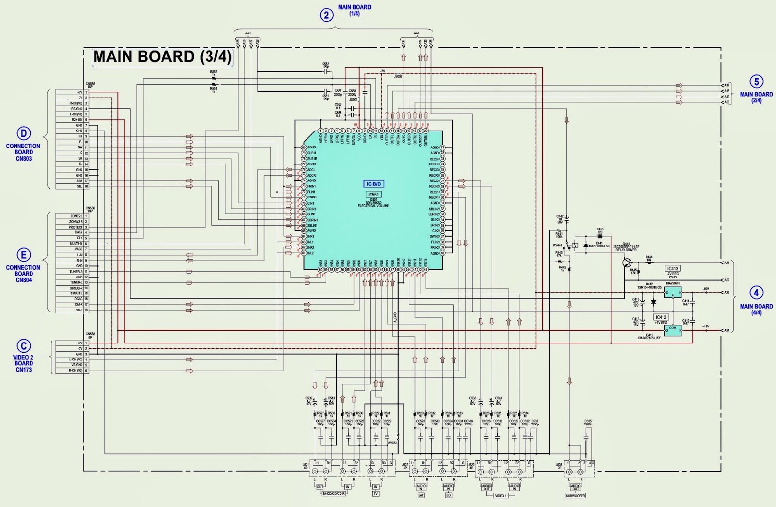
CLICK ON THE TABLE TO ENLARGE 


MIVAR 14M4 - COLOR TV - SCHEMATIC [Circuit Diagram] - TEA2261 – TDA6404 – TDA8840 – TDA8356 – TDA7056B

$
0
0

SCHEMATIC -FULL
CLICK ON THE PICTURES TO MAGNIFY 

GE 32GLED30 - LED TV - POWER SUPPLY [SMPS] - SCHEMATIC

$
0
0

POWER SUPPLY TROUBLESHOOTING [CLICK ON THE SCHEMATIC TO ZOOM IN]
WHITE SCREEN
BLACK SCREEN

TELEFUNKEN - TCP2567STX - SCHEMATIC [CIRCUIT DIAGRAM] - ( MC44608)

$
0
0


SCHEMATIC DIAGRAM
CLICK ON THE SCHEMATIC TO ZOOM IN 
SMPS [POWER SUPPLY] ONLY

HISENSE LHDN26W57 [MT5380 Chassis] - LCD TV - HOW TO ENTER SERVICE MODE - AGING MODE

$
0
0

SERVICE MODE
With factory RC (remote control)
  • Press "M" button and enter factory mode.
  • Press "Menu" button and enter factory OSD menu.
  • Press "CH+"/"CH-" button select the function menu, press "VOL+"/"VOL-" enter the selected function menu. Press "VOL+"/"VOL-" button adjust values in the menu.
With user's RC
  1. Power TV On
  2. Press Menu button and call up User OSD Menu
  3. Select Audio > Balance
  4. Enter 0>5>3 2 in sequence. [Note: If necessary, re-do number keys.]
  5. Factory OSD appears.
  6. Press Menu again and leave factory OSD.
WHITE BALANCE
 [Note: Different source has different WB values. Before adjusting, please change to desired source.]
Auto Color
For VGA and Component Video sources, WB values must be adjusted.  Before adjusting, prepare the signal instruments such as DVD or K-8256 first, and find the video picture with gray and color bars. Then change to desired source.
  • Press ‘M’ button and enter the factory mode.
  • Press ‘Menu’ button and enter factory OSD menu.
  • Select the item ‘Auto Color’.
  • Press ‘Vol +’ button to auto color.
  • Close the OSD menu after 5 seconds.
Clear the EEPROM
Note: The factory menu date varies according to different sources. Incase changing the factory data by error, you can choose to "Clean Protected", by which you can resume the default value, To clear the EEPROM:
  1. Select the item ‘Clean All’.
  2. Press ‘Vol +’ button to clear the EEPROM data.
  3. Close the OSD menu after 5 seconds.
  4. Restart the TV.
To Exit the Aging Mode
If there is a red "M" moving on the screen, it mean the TV is in Aging mode.
To exit the Aging mode, use your user RC, and enter 80 87 in sequence.

EMERSON LC320EM9 - POWER SUPPLY - BACK-LIGHT INVERTER - SCHEMATIC [Circuit Diagram]

$
0
0

BACK-LIGHT INVERTER
AUDIO OUTPUT
CLICK ON THE SCHEMATICS TO MAGNIFY

HOW TO ADJUST WHITE BALANCE - ADJUSTMENT - LG42LH70YD - LCD TV

$
0
0

WHITE BALANCE ADJUSTMENT
Test Equipment: CA-210
Using LCD color temperature, Color Analyzer (CA-210) must use CH 9, which Matrix compensated (White, Red, Green, Blue compensation) with CS-2100. See the Coordination bellow.
Manual adjustment sequence is
  • Turn to "Ez-Adjust" mode with press ADJ button of service remocon.
  • Select "10.Test Pattern" with CH+/- button and press enter. Then set will go on Heat-run mode. Over 30 minutes set let on Heat-run mode.
  • Let CA-210 to zero calibration and must has gap more 10cm from center of LCD module when adjustment. 
  • Press "ADJ" button of service remocon and select "7.White-Balance" in "Ez-Adjust" then press "Ü" button of navigation key.  (When press "Ü" button then set will go to full white mode)
Adjust at three mode (Cool, Medium, Warm)
  • If "cool" mode ; Let B-Gain to 192 and R, G, B-Cut to 64 and then control R, G gain adjustment High Light adjustment.
  • If "Medium" and "Warm" mode; Let R-Gain to 192 and R, G, B-Cut to 64 and then control G, B gain adjustment High Light adjustment.
  • All of the three mode; Let R-Gain to 192 and R, G, B-Cut to 64 and then control G, B gain adjustment High Light adjustment. [With volume button (+/-) you can adjust.]
  • After all adjustment finished, with Enter (Ykey) turn to Ez-Adjust mode. Then with ADJ button, exit from adjustment mode.
Attachment: White Balance adjustment coordination and color temperature.
Using CS-1000 Equipment.
COOL : T=11000K, ¦uv=0.000, x=0.276 y=0.283
MEDIUM : T=9300K, ¦uv=0.000, x=0.285 y=0.293
WARM : T=6500K, ¦uv=0.000, x=0.313 y=0.329
EYE-Q Function checks.
  1. Turn on TV
  2. Press EYE Key of Adj R/C
  3. Cover the Eye Q II sensor on the front of the using your hand and wait for 6 seconds
  4. Confirm that R/G/B value is not lower than 10 of the ‘Raw Data (Sensor data, Back light)”. If after 6 seconds, R/G/B value is not lower than 10, replace EYE Q II sensor.
  5. Remove your hand from the EYE Q II sensor and wait for 6 second
  6. Confirm that “OK” pop up. If change is not seen, replace EYE Q II sensor.

LG42LH70YD LCD TV - NO POWER - NO BOOT-UP - NO OSD TROUBLE SHOOTING

$
0
0

POWER BOOT-UP FAIL
NO ON-SCREEN DISPLAY


SAMSUNG _ HCL - HD4715W - PROJECTION TV - POWER SUPPLY SCHEMATIC

$
0
0

POWER SUPPLY SCHEMATIC
HORIZONTAL OUTPUT
VIDEO OUTPUT [CRT BASE CARDS]
CLICK ON THE SCHEMATICS TO MAGNIFY

PANASONIC PLASMA TV - LED BLINKING CODES - TROUBLESHOOTING

$
0
0

LED BLINKING CODES - TH-42PX75U_TH-50PX75U_TH-42PX77U_TH-50PX77U
LED BLINKS ONCE [CLICK ON THE PICTURES TO ZOOM IN]
The A board is defective. To confirm this, unplug the TV and disconnect connectors A5, A6, and A7 from the A board. The TV should turn on automatically and display a white screen.
2-BLINKS
3 - BLINKS
5 - BLINKS

SONY STR-KM7600 (Australia) - MAIN BOARD - SCHEMATIC [Circuit Diagram) [STK350-530T-E]

$
0
0

MAIN PWB
SCHEMATICS
CLICK ON THE PICTURES TO MAGNIFY 

HOW TO DISASSEMBLE - SONY STR-KM7600 - MULTI CHANNEL AV RECEIVER [Australia]

$
0
0

CASE
BACK PANEL
FRONT PANEL
MAIN BLOCK
HEAT SINK BLOCK_MAIN BOARD
CLICK ON THE PICTURES TO MAGNIFY

POWER SUPPLY [SMPS] SCHEMATIC (STR-8656 or STR-5653) - KONKA P2976S - P2171S - T2172S - T2173S

$
0
0


SMPS SCHEMATIC
CLICK ON THE SCHEMATIC TO ZOOM IN

SONY KLV17HR-1 LCD TV - HOW TO REMOVE BACK COVER - STAND - H-2 BOARD - D-1 BOARD

$
0
0

REAR PANEL           [ CLICK ON THE PICTURES TO ZOOM IN ]
REAR COVER & STAND BLOCK
H2 BOARD REMOVAL
D-1 BOARD REMOVAL

HOW TO ENTER SERVICE MODE - SONY KLV17HR1 - POWER SUPPLY SCHEMATIC

$
0
0

SERVICE MODE
(1) Send “TEST” command by Test Commander.
Or fix the accompanying RC as follows.
(1) Select ‘TV’ by SELECTOR button.
(2) Keep pushing the yellow button on the RC during LED of TV turning on.
(3) Remain pushed till the TV-selected LED blinking get slower (about 10 seconds).
(4) Push “9” key five times and TV, VCR, and DVD all turns on then off.
(5) Press ‘VIDEO I/O’ key toward the object set.  (The procedure above enables RC to always release “TEST” command.)
(To reset, follow the above procedure except (4); “0” instead of “9”)
How to exit of ‘Service’ mode
(1) Send “TEST” command by Test Commander.
Or
(2) Select “FACTORY MODE EXIT” in ‘Service’ menu, then press “OK” key.
POWER SCHEMATIC


HBUSTER HBTV - 32D05HD - POWER SUPPLY [SMPS] SCHEMATIC (Circuit Diagram)

$
0
0

POWER SUPPLY
CLICK ON THE SCHEMATICS TO ZOOM IN

LG 47LM6200 - LED LCD TV - HOW TO DOWNLOAD - MAC Address, ESN Key and Widevine Key download

$
0
0

DOWNLOAD PROCEDURE
Equipment & Condition
1) Play file: keydownload.exe
Communication Port connection
1) Key Write: Com 1,2,3,4 and 115200 (Baudrate)
2) Barcode: Com 1,2,3,4 and 9600 (Baudrate)
Download process
1) Select the download items.
2) Mode check: Online Only
3) Check the test process
- DETECT  ->  MAC_WRITE  ->  ESN_WRITE  ->  WIDEVINE_WRITE
4) Play : START
5) Check of result: Ready, Test, OK or NG.
Communication Port connection
1)  Connect:  PCBA  Jig  ->  RS-232C  Port  ==  PC  ->  RS-232C Port
Download
11Y LCD TV + MAC + Widevine + ESN KeY

VIDEO ERROR - TROUBLESHOOTING - LG47LM6200 LED LCD TV

$
0
0

NO VIDEO/NORMAL AUDIO
Check White Balance value
Entry method
1. Press the ADJ button on the remote controller for adjustment.
2. Enter into White Balance of item 6.
3. After recording the R, G, B (GAIN, Cut) value of Color Temp (Cool/Medium/Warm), re-enter the value after replacing the MAIN BOARD.
CLICK ON THE PICTURES TO MAGNIFY
NO VIDEO/AUDIO
Power board voltage measuring method
Check DC24V, 12V, 3.5V
VIDEO ERROR - VIDEO LAG / STOP
TUNER input signal strength checking method
LCD-TV Version checking method
VERTICAL/HORIZONTAL BAR
Tuner checking part and procedure
Checking method:
1. Check the signal strength or check whether the screen is normal when the external device is connected.
2. After measuring each voltage from power supply, finally replace the MAIN BOARD.
COLOR ERROR
Adjustment Test pattern - ADJ Key
You can view 6 types of patterns using the ADJ Key
Checking item :
1.Defective pixel
2.Residualimage
3.MODULE error (ADD-BAR,SCAN BAR..)
4.Video error (Classification of MODULE or Main-B/D!)

ATTACK MK6200 - [MARK AUDIO] - AMPLIFIER - SCHEMATC [CIRCUIT DIAGRAM]

$
0
0

SCHEMATICS & LAYOUT
CLICK ON THE PICTURES TO MAGNIFY

LG - MCV904 (MCS904F/S/W/AW) - SMPS (Power Suppy) - SCHEMATIC (Circuit Diagram)

$
0
0

SMPS SCHEMATIC
CLICK ON THE PICTURES TO MAGNIFY 

Viewing all 2033 articles
Browse latest View live


<script src="https://jsc.adskeeper.com/r/s/rssing.com.1596347.js" async> </script>