Quantcast
Channel: Electro help
Viewing all 2033 articles
Browse latest View live

DENON DVD 5000 HOW TO REMOVE THE DISC ON THE TRAY IN TROUBLE

$
0
0
TO REMOVE THE DISC ON EMERGENCY
* Remove the Top Cover first.
* Remove the 6 screws (1) on the top, 4 screws (2) on both sides and 2 screws (3) on the rear.
* Remove the top cover while spreading it slightly and lifting it upward.
* When the disc does not eject even after pushing the OPEN/CLOSE button, remove the disc as follows:
* Perform this procedure after the top cover has already removed.
* Remove the 5 screws (4) on the top and the 4 screws (5) on the rear side.
* Remove the top plate assembly while shifting it to the arrow direction after disconnecting the wire.
* Remove the clamp support plate by removing the 4 screws (8).
* Remove the disc, taking care not to damage it.
Reverse the procedure to reassemble.


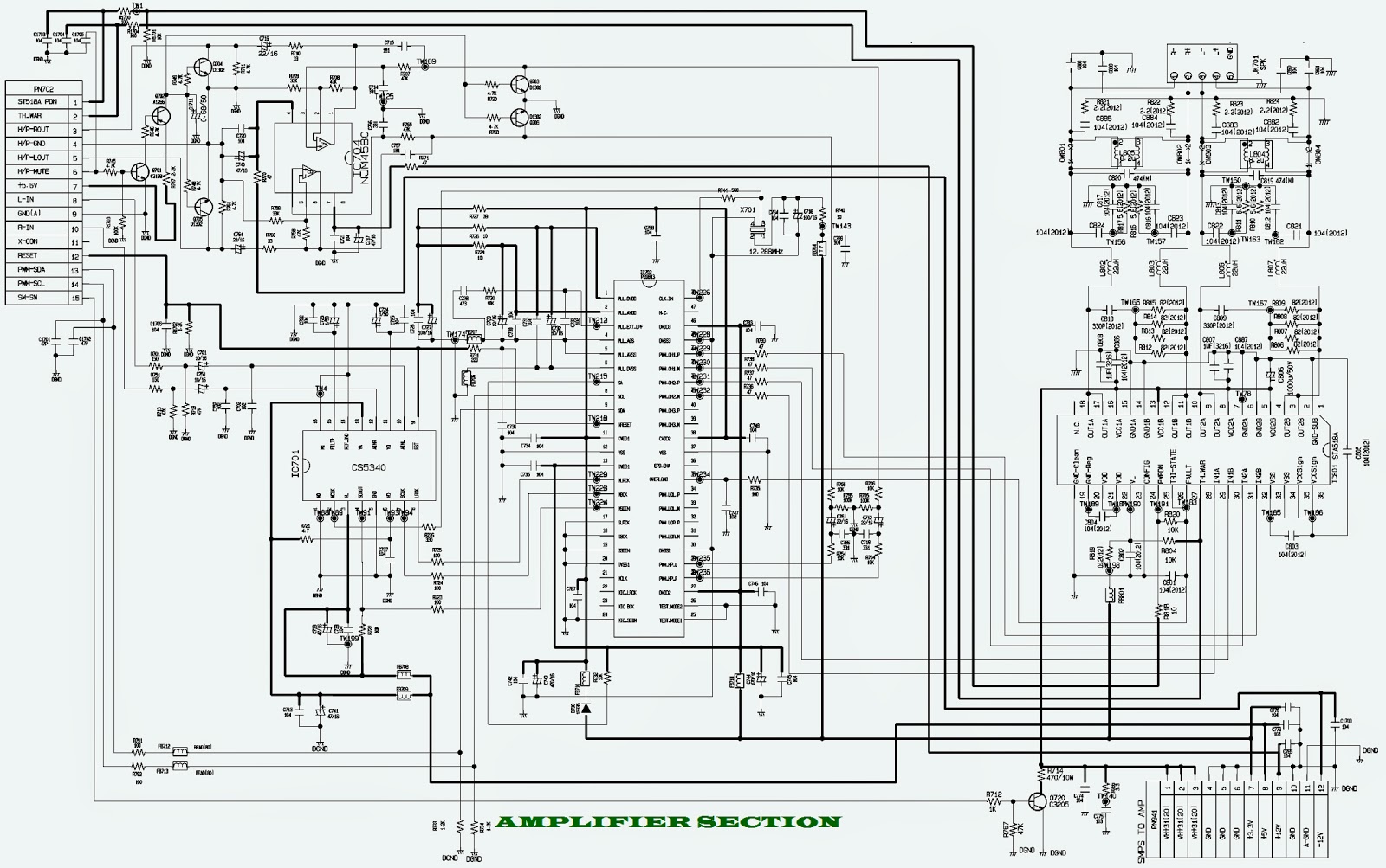
HARMAN KARDON HK 970 - HK230 INTEGRATED AMPLIFIER POWER SUPPLY – POWER AMP - SCHEMATIC

$
0
0
harman kardon HK970/230 - power supply and power amplifier circuit diagram
POWER SUPPLY 
POWER AMPLIFIER
CLICK ON THE SCHEMATICS TO ZOOM IN

SIGNATURE 1.5 harman kardon - Power Supply and Power Amplifier Schematic

$
0
0
HARMAN KARDAON _ SIGNATURE 1.5 _ POWER AMPLIFER _ POWER SUPPLY & AMPLIFER CIRCUIT DIAGRAM. [Click on the Pictures to Magnify]

POWER SUPPLY
POWER AMP (One channel is shown.  Other is similar)

AKAI DVD PLAYER - A4281– A4283 – A4162 – A4191 - SMPS SCHEMATIC

$
0
0
SMPS
CLICK ON THE SCHEMATIC TO ZOOM IN

SONY BDP S370 - SERVICE MODE - BU and BU ASSEMBLY REPLACEMENT

$
0
0
BU & BU Assy Replacement Procedure.
Applicable to Sony BDP-BX37/S270/S370/S373/S470.
BU REPLACEMENT
Before BU Replacement.
* Enter Service Mode: Press < OPEN/CLOSE>, < PLAY>,< STOP> and plug in AC Power.
* Inside *Service Mode Menu Select [8] Drive.
* Inside *Drive Select [7] OP Check Menu.
* Inside *OP Check Menu Select [3] dIOP then press 'ENTER'.
* Specification Diop BD: 6mA DVD, CD: 9mA.  [If no - IOP out of specification need BU replacement > Optical Block Unit (BU) replace] {If Yes AC Power OFF}.
BU (Optical Block) Repair. BDP 5G (BDP-S370) series component structure is as same as conventional DVD Players.   However BD player requires precise read out functions and also secure contents Protection system.  Since above requirement, it is necessary to set/adjust BU data to EEPROM.
The following cases need Adjustments;
(1) Replace BU (MB is original)
(2) Replace MB (BU is original)
(3) Replace both BU and MB.
JIG Requirement
# Digital camera (recommend with macro mode)
# Barcode decoder (5GBUJIG) installed in JIG PC’s
# USB memory
# ESD work bench.
The servo adjustment procedure will be carried out during OP data writing.  There is no manual adjustment procedure. LD ON TIME history doesn’t carry over. Do not touch any optical block parts, Turn Table and during replacing. BD Laser diode is very sensitive.
BU Adjustment.
* Remove the defective BU from Loading Assy and also remove BU insulator (4pcs)
* Unpack new BU and take OP Data Barcode photo by camera.
* Assemble BU with Insulators to Loading Assy (tighten screw with 2kgf)
* Decode the OP Data Barcode photo using BDBUDEC.exe and save the test data to USB memory (File Name: BuData.txt)
* Enter Service Mode and insert USB memory to USB connector.
* Select [8] Drive > Select [1] Drive OP data Write > Select [2] Mode: 1 or 2 Press ENTER. {Mode: 1 BDP-BX37/S270/S370/S373/S470}{Mode:2 BDP-BX57/S570}
* After Finishing ReWrite OP data  > Turn AC Power OFF And confirm dIOP by select [7] OP Check Menu to verify IOP in specification.
* IOP in specification > Turn AC Power OFF.
* Turn Power ON and check playback performance using BD,DVD & CD.
In case of BU assy replacement:
  • OP related data for new assy is controlled by BU factory
  • All of data is recorded into a barcode label
  • The label is put on the assy
  • Service parts will be followed
  • In service, the data should be read out from problem assy
  • The read data should be saved to new assy.
Fact finding:
  • The label is “DATA MATRIX” format
  • The number of data is 91 words
  • The method of reading and saving is required when BU and main board are replaced.
  • All of BU data on the barcode label is shot by digital camera in order to make a JPEG file of BU data.
  • Application software in the PC makes digital data from JPEG file.
  • The converted data is stored to USB memory.
  • The USB memory is connected to BDP 5G unit.
  • In service mode, there is a command to save the data from USB memory to board memory.
The application software will be a service jig with J parts number as service jig, and the recording media will be CD-R.
PN: J6090212A
Description: BDBUDEC
When instruction to PC, password is required.
[The password will be supplied to only service HQ, and service center name, q’ty and all of software registered information should be maintained by service HQ, and Video will ask to report the registration information.]

LG LM-U550A - LM-U550D - LM-U550XLMS-U550 - 3CD CHANGER DVD _ DISASSEMBLE

$
0
0
LG 3CD CHANGER DVD_LM-U550A - LM-U550D - LM-U550XLMS-U550 _ Exploded Views 
Click on the pictures to Zoom In

3-CD CHANGER DVD – SCHEMATICS - LG - LM-U550A, LM-U550D, LM-U550XLMS-U550

$
0
0
LG LM-U550A, LM-U550D, LM-U550XLMS-U550_ 3CD CHANGER DVD - Circuit Diagram:  {How to reset to Initial Status}
CLICK ON THE CIRCUIT DIAGRAM TO MAGNIFY
To reset to Initial Status
HOW TO CLEAR MALFUNCTION
You can reset your unit to initial status if malfunction occur (button malfunction, display, etc.).
* Using a pointed good conductor (such as driver), simply short the RESET jump wire on the inside of the volume knob for more than 3 seconds.
* If you reset your unit, you must reenter all its settings (stations, clock, timer)
NOTE:To operate the RESET jump wire, pull the volume rotary knob and release it.   If you wish to operate the RESET jump wire, it is necessary to unplug the power cord.

To know more about disassemble & exploded view; pull up the previous post.

LG LST-3510A – SET-TOP BOX - CIRCUIT DIAGRAM

$
0
0
AUDIO PROCESSING - AUDIO & VIDEO OUTPUT - SMPS (POWER) -  Circuit diagram.
SMPS
AUDIO & VIDEO
AUDIO PROCESSING
DECK MECHANISM {EXPLODED VIEW}
CLICK ON THE PICTURES TO MAGNIFY 


SYSTEM UPGRADE and FACTORY MODE - LG SET-TOP BOX LST3510A

$
0
0
SYSTEM UPGRADE_ diagnostic Software Application - factory mode.
System Software Up-date
* Connect the service connector and the PC serial port by the serial cable, and execute PC UART Terminal (TeraTerm) program.
* At this time, T Terminal setting should be as follows:  (Port/Baud rate/Data/Parity/Stop/Flow control)=(Com*/115200/8bit/none/1bit/none)
* When UART Terminal(TeraTerm) is connected
> While pressing “B”or “b”press [Power] button of LST-3500 to input the power. > (1)
> When the following [Boot Menu] is displayed and then “Select Menu:”is displayed, enter “1” > (2)
> When [Download Boot Code or Application!] is displayed, enter “1” > (3)
>  Send Application Code(*.dnf)..”is displayed at the UART Terminal(TeraTerm) window, which means that the preparation for S/W Up-data is ready.
> Select “Send file”from UART Terminal(TeraTerm) File Menu and then select Up-data file(*. dnf). At this time, you should select [binary] of Option.
* After the file transfer is completed, the system automatically decompresses the received file and writes it into the flash memory.
*  After the writing is completed, the S/W rebooting will be executed.
Diagnostic Software application
H/W Diagnostics
It checks the hardware device driver of the ATSC board at the device driver level for securing the quality of the product at the printed circuit board state.
How to enter into H/W diagnostics
> As shown at, connect the serial cable via the PC and the service port of the LST-3500, and, while holding down ‘s’ or ‘S’ of the keyboard, turn on the LST-3500.
> As shown, when the initial screen of the hardware diagnostics is displayed at the Tera Term terminal, it is normally entered into the hardware diagnostics.
Or
> Connect the serial cable via the PC LST-3500 service port, and then turn on the LST-3500 while holding down ‘b’ or ‘B’ of the keyboard.
> Boot menu is displayed at the Tera Term terminal, and when you select H/W Diagnostics Test(0x8000) from the menu, then the initial screen of the hardware diagnostics is displayed as shown.
Configuration of Hardware diagnostics
Hardware diagnostics menu consists of the followings as shown. [ Test scope ]
>> Testing CPU CORE and internal peripherals within CPU
>  System SDRAM Test
Read/Write Specific portion of 8M SDRAM (system memory)
> Testing CPU IIC0 connected device
Read/Write VSB Decoder register of Digital tuner.  Read/Write SPDIF(CS8415) register.
> Testing GPIO IIC1(Pseudo -IIC) connected device
Read Status register/Write Tuning data of Digital tuner.  Read/Check EEPROM(24LC256).  Check Volume Controller (TDA7440D): Write Volume change data.
> SIO (Synchronous Input Output) Test
Process Front MiCOM key input.  VFD ON/OFF
> HD2 Video Test
HOST I/F: Testing Register Read/Write (CPU<>HD2)
HD2 SDRAM Read/Write test (Normal/DMA)
HD2 Video External Output (Color pattern)
Running Hardware Diagnostics
It automatically checks the entire ATSC board by executing BIST (Built In Self Test) from [TEST MENU].  Other items from TEST MENU are for displaying failure details and tracing failed part. ‘a’ is for jumping to Main program for executing the function of Digital broadcasting receiver and ‘r’ is for rebooting the ATSC board.
Factory Mode Diagnostics
It sets the check channel and initializes the shipment mode for shortening the time to check the front board at the SET state by displaying the S/W information under the condition that only the basic DTV functions are operating.
How to enter into Factory Mode Diagnostics
Connect Normal TV composite, Ready TV component, and RGB of PC monitor to PC “LST-3500”Video output port, and wait for the initial screen by pressing both Volume +’ key and ‘Stop’ key of the front board at Power-on state of LST-3500. If the initial screen is displayed as shown at Figure 3.2.2.1-6, it is successfully entered into the normal factory mode diagnostics.
Configuration of Factory Mode Diagnostics  [ Test scope ]
> Model information and S/W version information
> Front board test Local keys of Front board: Testing all of keys except Power key VFD output test of Front board.
> Set the test channel used for a process test: Broadcasting channel and In-house signal channel
> Initialize the shipment mode. Set NVRAM data to the product shipment mode.
Executing Factory Mode Diagnostics
‘Enter’ key, ‘Channel +’ key, ‘Channel - ’ key, and ‘Menu/Default’ key of the front board are used for scrolling the diagnostics menu and executing the menu item.
> ‘Channel +’ key and ‘Channel - ’ key are used for scrolling the menu.
> ‘Enter’ key is used for executing the selected menu item.
> ‘Enter’ key is used for executing and ‘Menu/Default’ key is used for returning to the previous.
> For exiting from the factory mode diagnostics during scrolling the menu, press ‘Menu/Default’ key to reboot and to exit.
> For normally exiting from the factory mode diagnostics, select ‘Exit’ menu item to reboot and to exit.

HOW TO DISASSEMBLE LG LST-3510A – SET-TOP BOX - DECK MECHANISM

$
0
0
HOW TO DISASSEMBLE DECK MECHANISM

Holder Clamp.
1) Release 2 Screws (S1).
2) Unhook 2 Locking Tabs (L1).
3) Lift up the Holder Clamp and then separate it from the Base Main.
Clamp Assembly Disc
1) Place the Clamp Assembly Disc as Fig. (A)
2) Lift up the Clamp Assembly Disc in direction of arrow (A).
3) Separate the Clamp Assembly Disc from the Holder Clamp.
Plate Clamp
1) Turn the Plate Clamp to counterclockwise direction and then lift up the Plate Clamp.
Magnet Clamp
Clamp Upper.
Tray Disc
1) Insert and push a Driver in the emergency eject hole(A) at the right side, or put the Driver on the Lever (B) of the Gear Emergency and pull the Lever (B) in direction of arrow so that the Tray Disc is ejected about 15~20mm.
2) Pull the Tray Disc until it is separated from the Base Main completely.
Base Assembly Sled.
1) Release 4 Screw (S2).
2) Disconnect the FFC Connector (C1)
Gear Assembly Feed
Unhook the Locking Tab (L2) in direction of arrow.
Gear Middle
Gear Assembly Rack
Release the Screw (S3)
Rubber Damper.
Frame Assembly Up/Down.
Put the Base Main face down(Bottom Side)
1) Release the Screw (S4)
2) Unlock the Locking Tab (L3) in direction of arrow and then lift up the Frame Up/Down to separate it from the Base Main.
NOTE: When reassembling move the Guide Up/Down in direction of arrow(C) until it is positioned as Fig.(C).  When reassembling insert (A) portion of the Frame Assembly Up/Down in the (B) portion of the Guide Up/Down as Fig.(B)
Belt Loading.
Put the Base Main on original position (Top Side)
Gear pulley.
Unlock the Locking Tab (L4) in direction of arrow(B) and then separate the Gear Pulley from the Base Main.
Gear Loading.
Guide Up/Down.
Move the Guide Up/Down in direction of arrow(A) as Fig.(A)
Push the Locking Tab(L5) down and then lift up the Guide Up/Down to separate it from the Base Main.
NOTE: When reassembling place the Guide Up/Down as Fig.(C) and move it in direction arrow(B) until it is locked by the Locking Tab(L5). And confirm the Guide Up/Down as Fig.(A).
PWB Assembly Loading
Put the Base Main face down(Bottom Side)
1) Release 2 Screws (S5)
2) Unlock the Loading Motor (C2) from the Hook (H1) on the Base Main.
3) Unlock 2 Locking Tabs(L6) and separate the PWB(PCB) Assembly, Others from the Base Main.

XOCECO LC 30 - LC40D9 - LCD TV - TROUBLESHOOTING - SERVICE MODE - Factory Reset

$
0
0
TROUBLESHOOTING
(Press remote control or BOX power button, then the red indication lamp power off, in normal condition the lamp change from red to blue.)
NO SCREEN DISPLAY _ BACK-LIGHT ON
NO SOUND
DIGITAL BOARD TROUBLESHOOTING
Display box "SEARCHING"

NO PICTURE
MONITOR BOARD PROBLEM: MONITOR works normally, but can’t test box, it maybe cause by the following problem.
HOW TO ENTER SERVICE MODE [FACTORY MODE]
* Push the “Rest” key and “OK” key under the cover of the remote control set, repeat the push, enter the factory menu.
* Select factory reset to initialize the MONITOR

VESTEL 17IPS-01 - POWER SUPPLY SCHEMATIC - INVERTER

$
0
0
Vestel 17IPS 01-1 power supply schematic - Back-light inverter
SCHEMATIC - [SMPS] & [INVERTER]

HOW TO DISASSEMBLE AOC LC32D1322 LCD TV

$
0
0
DISASSEMBLY
* Remove the screws to remove BASE.
* Remove the screws to remove REAR COVER.
* Remove the screws to remove MAIN BOARD, POWER BOARD, SPEAKERS and BKT.
* Remove the screw to remove BKT.
* Remove the screws to separate the Panel and Bezel, remove the screws to remove IR BOARD.

AOC LC32D1322-LC42D1322-LE32D1322 POWER SUPPLY [SMPS] SCHEMATICS

$
0
0
LC32D1322 [715G4088P02W30003H] SMPS
LE32D1322 [715G5259P01W20002M]
LC42D1322 [715G3829P03W30003S]
CLICK ON THE SCHEMATICS TO MAGNIFY

HOW TO DISASSEMBLE AOC LC42D1322 LCD TV

$
0
0
DISASSEMBLE [LC-42D 1322]
* Remove the screws to remove BASE
* Remove the screws to remove REAR COVER.
* Remove the screws to remove MAIN BOARD, POWER BOARD, IR BOARD, SPEAKERS and BKT.
* Remove the screws to remove BKT.


LG 50PQ30 50G2 PLASMA TV - BOARDS AND VOLTAGE DETAILS

$
0
0
LG 50PQ30  PLASMA-(SMPS) POWER SUPPLY BOARD_Y-SUS BOARD_Y-DRIVE BOARD_Z-SUS BOARD_ Location and reference voltages. [CLICK ON THE PICTURES TO ZOOM IN]
POWER SUPPLY [SMPS]
Y-SUSTAIN BOARD
Y-DRIVE BOARD
Z-SUSTAIN BOARD

50PQ30 - LG PLASMA TV - INTERCONNECTION AND POWER SUPPLY START UP SEQUENCE

$
0
0
INTERCONNECTION AND POWER SUPPLY START UP SEQUENCE_LG50PQ30 _ 50" PLASMA TV
INTERCONNECTIONS
START-UP SEQUENCE
CLICK ON THE PICTURES TO MAGNIFY 

SET SHUTS DOWN AT TURN ON - LG50PQ30 - PLASMA TV

$
0
0
* Top or Bottom ½ of the picture is black. 
** SHUT DOWN AT TURN ON
* When the set turns on, either the Top or Bottom ½ of the picture is black.
# It is possible that the whole picture could be black if P207 or P207(Y-SUS) is involved.
# Look carefully the connections between the Y-SUS and Upper and Lower Y-Drive boards.
# It is possible that these can be improperly seated.
# Remove and re-seat the board correctly.  
Note:This can happen if either the Y-SUS or Y-Drive boards are replaced or pulled off to perform checks.
SHUT DOWN AT TURN ON
Check
* V-Scan signal input to Lower Y-Drive board low ohms or low volts (Diode Mode).
* Output from any buffer shows low ohms or low volts (Diode Mode).
Defective Y-Drive Upper or Lower
After determining which Y-Drive board is defective using the checks, the other board can be tested separately.
* If the Upper Y-Drive is found defective, the Lower Y-Drive board can be tested. 
  > Remove the Upper Y-Drive. Disconnect the Connector P209. 
  > Turn on the set and confirm that the bottom half of the picture looks normal.
* If the Lower Y-Drive is found defective, the Upper Y-Drive board can be tested.  
  > Remove the Lower Y-Drive. 
  > Disconnect the Connector P209.
* Jump either Pin 1 or 2 of P207 (V-Scan from the Y-SUS) to pin 4 or 5 of connector P108 on the Upper Y-Drive board.
* Turn on the set and confirm that the top half of the picture looks normal.
Click on the pictures to Magnify

PLASMA TV LG50PQ30 - Z-SUSTAIN BOARD PROBLEMS AND CURES - Back cover removal

$
0
0
(1) When the set turns on and a picture appears, the bottom of the picture shows the Input selection screen.
The Remote did not work.
(2) The panel indicates a brief flash during start up, then “No Picture”
PICTURE APPEARS WITH SELECTION SCREEN AT THE BOTTOM
The Front Function Keys did not work. (Except the Main Power Switch)
*  Main Board: Reading the Key 1 and Key 2 lines found that Key 2 was at 0.8V. Key 1 read normal at 3.3V.
*  Feeling the Function buttons found that the right hand button (as viewed from the rear) did not feel the same as the others. It was stuck.
Remove and re-position the button assembly.
A brief flash at start-up, but no picture.
* Z-SUS does not produce a correct signal. (All voltages check normal except 17V).
* Y-SUS does not produce a correct signal. (No negative portion).
* On Y-SUS: 17V starts off at 17V then very quickly drops to 5V.
* Floating Ground 5V and 15V are not produced.
* Removing all connectors on the Z-SUS board (Except the panel connectors) does not change test results.
* Removing Y-Drive boards cause all voltages to return to normal. Including the Y-Drive signal checked on the right side of C213.
* Reconnecting all connectors on the Z-SUS board shows it is not creating a correct waveform. Just spikes. (17V now stays up).
* Using the Diode Checks for the Y-Drive boards do not indicate a problem.
Replace the Z-SUS board.
BACK COVER REMOVAL

POWER SUPPLY BOARD [SMPS] CHECKING PROCEDURES – LG50PQ30 50” PLASMA TV

$
0
0
POWER SUPPLY BOARD [SMPS] OPERATION PRINCIPLE_VOLTAGES_Va & Vs Adjustments.
OPERATION PRINCPLE
  AC Voltage is supplied to the SMPS Board at Connector SC101 from the AC Input assembly. Standby 5V is developed from 160V source supply (which during run measures 380V measured from the primary fuse F302). This supply is also used to generate all other voltages on the SMPS.  The STBY5V (standby) is B+ for the Controller (IC701) on the SMPS and output at P813 pins 11 and 23 then sent to the Main board for Microprocessor (IC1) operation. AC Detect is generated on the SMPS, by rectifying a small sample of the A/C Line at D102 and associated circuitry and routed to the Controller (IC701) where it outputs at pin 15 and sent to P813 pin 18 to the Main Board where it is sensed and monitored by the Main Microprocessor (IC1). The AC Det in this set works differently than most. If AC Det is missing the Microprocessor will turn off the television in about 10 seconds after turn on.
This will happen each time turn on is attempted.
  A new feature included on the side keypad is called a Main Power Switch which opens a ground allowing the “Key On” line of P813 Pin 24 to go high, turning off the 5V STB line defeating the Micro Processor (IC1) on the Main Board and Remote Control Operation. When the Microprocessor (IC1) on the Main board receives an “ON“ Command from either the Power button or the Remote IR Signal, it outputs a high called RL ON at Pin 19 of P813. This command causes the Relay-Drive Circuit to close both Relays RL102 and RL103 bringing the PFC source up to full power by increasing the 160V standby to 380V run which can be read measuring voltage at Fuse F302 and F801 from “Hot” Ground. At this time the run voltages 12V, and +5V sources become active and are sent to the Main Board via P813 (12V at pins 5 and 6 and 5V at pins 9,10, and 12). The 5V detect line from the SMPS Board to the Main Board can be measured at pin 17 of P813. It is not used. 
  The next step is for the Microprocessor (IC1) on the Main Board to output a high on M5V ON Line to the SMPS at P813 Pin 21 which is sensed by the Controller (IC701) turning on the M5V line and output at P811 pins 9 and 10 to the Y-SUS board P201 pins 9, 10. Then it Is routed to the Control and Z-SUS boards.  Full Power occurs when the Microprocessor (IC1) on the Main Board brings the VS-ON line high at Pin 20 of P813 of the SMPS Board. VS-ON is routed to the Controller (IC701) which turns on the 17V Audio, VA, and the VS supplies. VA and VS output at P811 to the Y-SUS board. (VA pins 6 and 7 and VS pins 1 and 2). The 17V Audio supply outputs to the Main board at P814 pins 1 and 2 and used for Audio processing and amplification.  
  AUTO GND Pin 22 of P813: This pin is grounded on the Main board. When it is grounded, the Controller IC701 works in the normal mode, meaning it turns on the power supply via commands sent from the Main board. When this pin is floated (opened), it pulls up and turns the Controller IC701 on in the Auto mode. In this state, the Controller turns on the power supply in stages automatically. A load is necessary to perform a good test of the SMPS if the Main board is suspect.
Va & Vs adjustments
These adjustments are a must; when power board [SMPS] or Display panel are replaced.  Details about these voltages will be marked on each panel, and will differ to each other.
HOW TO TEST THE POWER SUPPLY [SMPS]
Using two 100 Watt light bulbs (Filament Type Only), attach one end to Vs and the other end to ground. Apply AC toSC101. If the light bulbs turn on and VS is the correct voltage, allow the SMPS to run for several minutes to be sure it will operate under load. If this test is successful land all other voltages are generated, you can be fairly assured the power supply is OK.
Note: To be 100% sure, you would need to read the current handling capabilities of each power supply listed on the silk screen on the SMPS and place each supply voltage under the appropriate load.
Note: This SMPS will run without a load, however if the Vs is not loaded, the 17V may pulsate up and down.  It is always best to test the SMPS under a load using the 2 light bulbs.
POWER SUPPLY STATIC TEST
CONNECTOR P813 VOLTAGES & DIODE CHECK DATA
P813 CONNECTOR “SMPS" to “Main" P1006.
Note: The 17V turns on when the VS On command arrives.
Note: The 5V/12V turns on when the RL On command arrives.
Note: If the Key On line is 4.39V, the Main Power Switch is open.  Stand-By 5V will shut off.
Connector SC101 and P811 Identification, Voltages and Diode Check.

Viewing all 2033 articles
Browse latest View live


<script src="https://jsc.adskeeper.com/r/s/rssing.com.1596347.js" async> </script>