Quantcast
Channel: Electro help
Viewing all 2033 articles
Browse latest View live

SONY KV 28FX20A – KV 28FX201A – TRINITRON TV – MAIN POWER REGULATOR and STANDBY POWER – SCHEMATIC

$
0
0
KV 28FX20A – KV 28FX201ASONY TRINITRON TV – MAIN POWER and STANDBY POWER – SCHEMATIC
STR-S6709 (Power Driver) _SE135N-LF4 (Err Amp)
APPLICABLE TO:
KV-28FX20A RM-887 Italian SCC-Q22A-A
KV-28FX20B RM-887 French SCC-Q23A-A
KV-28FX20D RM-887 AEP SCC-Q21A-A
KV-28FX20E RM-887 Spanish SCC-Q24A-A
KV-28FX20U RM-887 UK SCC-Q25A-A
KV-28FX201A RM-887 Italian SCC-Q22C-A
KV-28FX201B RM-887 French SCC-Q23C-A
KV-28FX201D RM-887 AEP SCC-Q21C-A
KV-28FX201E
RM-887 Spanish SCC-Q24E-A
MAIN POWER REGULATOR SECTION
AV input, SIRCS, Front AV, St-By Power Supply
CLICK ON THE SCHEMATICS TO ZOOM IN


HOW TO DISASSEMBLE SAMSUNG UE40D8000Y LED LCD TV

$
0
0
SAMSUNG UE40D8000Y*_ UE46D8000Y* _ UE55D8000Y* _ UE60D8000Y* _ LED LCD TV _ Disassemble Procedure.
DISASSEMBLY
* Place TV faces down on cushioned table. Remove screws from the Stand.  Remove stand.
* Remove the screws of rear-cover.
* Lift up and remove the rear-cover.  * Caution: Be careful when you lift up the rear-cover, It’s really sharp.
* Remove the screws of middle-cover.
* Lift up and remove the middle-cover.  Caution: Remove the function cable, 3D emitter cable and deco cable before removing the middle cover.
* Remove the Speakers(R/L)
* Remove the Wi-Fi Module.
* Remove the screws of Main Board (Disconnect all cable connectors before removing any board.)
* Remove the screws of IP board.- Remove the IP board
* Remove the T-CON Bracket.

UE40D8000Y* SERIES SAMSUNG LED TV-NETWORK SETTINGS - PROBLEMS

$
0
0
Problems to Network Settings with Samsung UE40D8000 / UE46D8000 / UE55D8000 / UE60D8000 _ LED LCD TVS _ What's 3D
NETWORK SETTINGS 
  The One Foot Connection function lets you connect your Samsung TV automatically to Samsung wireless APs.  If your non-Samsung AP does not support One Foot Connection, you must connect using one of the other methods.
How to set up using One Foot Connection
1. Go to Network Settings screen.  To enter it, follow the directions of Network Settings.
2. Select the One Foot Connection.
3. Place the AP in parallel with the Samsung Wireless LAN Adapter giving a gap no larger than 25 cm.
4. Wait until the connection is automatically established.
5. The network test screen appears, and network setting is done.
6. Place the AP in a desired location
Network Settings (Plug & Access)
  Plug & Access function lets you connect your Samsung wireless Router to Samsung TV easily by using USB memory. If your non-Samsung AP does not support Plug & Access, you must connect using one of the other methods.   You can check for equipment that supports Plug & Access on www.samsung.com.
How to set up using Plug & Access Function
1. Turn on the power of AP and TV.  Insert USB memory stick into our Samsung wireless APs and checking AP’s LED status (blinking on).
2. Then take USB memory out and insert your USB memory into Samsung TV.
3. Wait until the connection is automatically established.
4. If Plug & Access does not connect your TV to your AP, a pop-up window appears on the screen notifying you of the failure. If you want to try using Plug & Access again, reset the AP, disconnect the Samsung Wireless LAN Adapter and then try again from Step 1 .  You can also choose one of the other connection setup methods.
5. The network test screen appears, and network setting is done.
6. Place the AP in a desired location.
7. If the AP settings change or you install a new AP, you must perform the Plug & Access procedure again, beginning from Step 1.
How to set up the network
Click the [Menu] button and open [Set-up] to select [Network]. Configure wired or wireless network settings.
How to check the network status
Select [Menu] ’ [Set up] ’ [Network] and run [Network Test] to see test results and check the network status.
In a network test over a wired connection, the second items which include the IP address, subnet, gateway and DNS server fail.
* If the IP address, subnet mask and gateway address were typed in manually, check that valid values were entered.  (For example, 0.0.0.0 is not valid for an IP address, subnet mask or gateway address.)
* If the IP address the user entered in is invalid, change it to a valid IP address.
In a network test over a wired connection, the third item, gateway ping fails.
* Check that the network cable is connected to the TV correctly.
* If the TV is connected correctly, check whether the IP address is automatic or manual.
* If the IP is automatic and connected to a sharing device, check the settings of the sharing device (AP) that is using a cable connection, or consult the corresponding Internet service provider.
* If the IP is manual, check if the IP address is entered correctly.  (Here, the user should confirm if the manual IP address entered in is valid.)
Cannot connect to a wireless network.
* If an encryption key must be entered in to connect to a sharing device, check that the correct password set for the sharing device is entered.
* Search surrounding sharing devices to see if there is a sharing device with the same SSID by selecting [Wireless Network Setup] and [Select Network].  If there is a sharing device with the same SSID, try to connect to this device.
* If the IP address is set to automatic and you cannot connect to the sharing device using option 1 or 2, check the settings of the sharing device to see if the DHCP server function on the sharing device is enabled. If disabled, activate the function. (For details on how to set up the sharing device, see the manual for the corresponding sharing device.)
* If you still cannot connect to the sharing device after confirming options 1, 2 and 3, reset the sharing device and try again.
When using a wireless network, the user’s wireless sharing device cannot connect to the PBC (WPS).
1. Check if the sharing device of the user supports WPS. (Refer to the manual of the sharing device.)
2. Check if the user pressed the PBC button on the sharing device.
3. If there is another sharing device with WPS running nearby, a connection cannot be made. Please retry after 2 minutes.
4. Reset the sharing device and retry.
5. If the sharing device of the user is not Wi-Fi certified, it may not be able to connect using WPS
The auto-configuring sharing device cannot be connected to automatically through a wireless dongle.  (Here, the user’s sharing device must support auto-configuration.)
1. Check if the sharing device of the user supports auto configuration. (For a list of sharing devices, refer to the IB or website.)
2. If the sharing device of the user supports auto configuration, place the sharing device as close as possible to the wireless dongle on the TV and try to re-establish the connection. (Must be placed close to the TV to establish a connection.)
Although the TV is placed close to the AP and the dongle is inserted into the TV, the sharing device cannot be connected to using auto-configuration.
Select [Menu] > [Setup] >  [Network] and check if SWL is Off.
Although the TV is placed close to the AP and the dongle is inserted into the TV, the sharing device cannot be connected to using auto-configuration and a message that it is connecting is displayed only.
* Check if the AP is not turned off during connection.
* If the AP is turned off, the TV will try to re-establish a connection for 2 minutes.
Although the TV is placed close to the AP and the dongle is inserted into the TV, the sharing device cannot be connected to using auto-configuration and a essage that it is connecting is displayed only.
* If Samsung Wireless Link is On, a 5G-bandwidth wireless sharing device may not be found in a search (restriction).
* If Samsung Wireless Link is Off or the product does not have the Samsung Wireless Link function, please retry searching to find the sharing device. (May not be found in a search depending on the settings of the wireless connection.)
In a network test over a wireless connection, the second items which include the IP address, subnet, gateway and DNS server fail.
* If the IP address, subnet mask and gateway were typed in manually, check that valid values were entered. (For example, 0.0.0.0 is not valid for an IP address, subnet mask or gateway address.)
* If the IP address the user entered in is invalid, change it to a valid IP address.
In a network test over a wireless connection, the third item, gateway ping fails
* If the IP address is automatic and connected to a sharing device, check the settings of the sharing device (AP) that is using a cable connection, or consult the corresponding Internet service provider.
* If the IP address is manual, check that the IP address is entered in correctly. (Here, the user should confirm if the manual IP entered in is valid.)
In a network test over a wireless connection, the fourth item, Internet service test fails.
Consult the corresponding Internet service provider (an Internet network service provider the user has subscribed to such as KT).
What is 3D Display?
A system that display 3D images artificially.
How?  By using binocular time delay.

1 Left eye recognizes left image, right eye recognizes right image.
2 Human eyes be far away each other 65 mm horizontally.  So each eye feels a little bit of time delay of left and right information.  Human brain merges those images and can feel three-dimensional.

GRUNDIG LENARO – SEDANCE – VIVANCE – HOW TO ENTER SERVICE MODE – SMPS SCHEMATIC

$
0
0

Lenaro 26 LXW 68-7731 IDTV GBG4500 / GBG4600  _ SEDANCE 26 LXW 68-6631 IDTV GBG5600 / GBG5700 _ Vivance 32-6731 DVB-T GBG3600 / GBG3700 
SERVICE MODE
Calling up the Service Mode
* Press button "i" (INFO).
* Enter the code number "8500".
To Exit the Service Mode
* Press button "TXT".
Functions of the buttons
          Call up the Dialog Center / close down the Menu
P+/P–  Call up the dialogue line (point of menu)
◄/►   Call up the Menus / Changing the settings
TXT   Exit the Service Mode
Software Version Number
The software version number is shown on the upper part of the service menu, e.g:
SLM. 512G 02 T07
11/08/06 11: 08: 59
G: SLM. 064 04 T00
Program Search
* Press button "i" (MAIN MENU).
* Select "Setup" with the buttons P+ / P– and confirm with button "OK".
* Select "Auto-program" with the buttons P+/ P– and confirm with button "OK".
* Select the required Country with the buttons P+/ P–, ◄/► and confirm with button "OK".
[The auto program system stops at every station of acceptable reception quality (AFC and coincidence) and stores the station data and the respective standard automatically. The system then continues searching.]
*Pressing the "i" button stops the program search.
Hotel Mode
Maximum volume is limited and there is no access to "Program Table" and "Setup" at activated hotel mode.
Call up: "i"> "8500"> P+/ P–"OPTION 1"> > P+/ P–"HOTEL"> ◄/  "YES".
Maximum volume: "i"> "8500"> P+ / P–"OPTION 1"> > P+ / P–"HOTEL VOL"> ◄/ Value 0…63.
Special Functions at activated Hotel Mode
The maximum volume can be adjusted in the additionally menu item "Maxvol" in the sound menu.
In addition there is access to the menus "Preset List" and "Channel Settings" until the set is switched off (standby).
Call up: "i"> "4658"
Display
If no picture is visible because of a wrong panel is adjusted, you can change the setting by "blind" adjust.
The following sequence of operating steps must be repeated until the picture is shown on the panel.
Call up: "i"> "8500">  > "P– "5 times > > "TXT"> switch set off and on.
If the picture is visible, then repeat the sequence once again and thereby adjust the correct type of panel (according to display label).
SMPS SCHEMATIC {Grundig & Beko}
CLICK ON THE PICTURES TO MAGNIFY

HOW TO ENTER SERVICE MODE - SOFTWARE UPGRADE - SAMSUNG UA46C6200UR LED TV

$
0
0
UA40C6200UR _ UA46C6200UR _ UA55C6200UR 
UA32C6900V* _ UA40C6900V* _ UA46C6900V* _ UA55C6900V*
Universal Remote Control Set-up Codes to Check with Samsung Brand TVs
SERVICE MODE
How to Access Service Mode; Using the Customer Remote
1. Turn the power off and set to stand-by mode
2. Press the remote buttons in this order; POWER OFF - INFO - MENU - MUTE - POWER ON to turn the set on.
3. The set turns on and enters service mode. This may take approximately 20 seconds.
4. Press the Power button to exit and store data in memory.  - If you fail to enter service mode, repeat steps 1 and 2 above.
Buttons operations within Service Mode
Menu> Full Menu Display/Move to Parent Menu
Direction Keys Up / Dn>  Item Selection by Moving the Cursor
Direction Keys Up/Dn>  Data Increase / Decrease for the Selected Item
Source> Cycles through the active input source that are connected to the unit
Initial SERVICE MODE DISPLAY State. Mode: CDTV . RES : 480I
Upgrading the Software
1. Insert a USB drive containing the firmware upgrade into the Wiselink Pro port on the side of the TV.
2.
If pop up is showed, press the exit or press the No button. (If you press Yes button, display is changed to Wiselink Pro Menu )
3.
Press the MENU button to display the menu.  Press the or button to select “Setup”, then press the ENTER button.
4.
Press the or button to select “SW Upgrade”, then press the ENTER button.
5.
Press the ENTER button.  The message “Scanning for USB... It may take up to 30 seconds.” is displayed.
6.
The message “Upgrade version XXXX to version XXXX?  The system will be reset after upgrade.” is displayed.  Press the or to select the “OK”, then press the ENTER button.
[Be careful to not disconnect the power or remove the USB drive while upgrades are being applied. The TV will turn off and turn on automatically after completing 
the firmware upgrade. Check the firmware version after the upgrades are complete. When software is upgraded, video and audio settings you have made will return to their default (factory) settings.]
Self Diagnostic
This is simple test function that judge whether is TV SET’s problem or not.
There are two self-test. Picture and Sound.
1. Press “Menu > Support > Self Diagnosis”  The message “Picture Test / Sound Test” is displayed.
2. Picture Test
1 The message “Does the problem still exist with this test pattern?” is displayed.
2 Press “Yes”. This is a TV SET problem.  The massage “Contact Samsung’s call center at 1-800-SAMSUNG for assistance.” is displayed.
3 Press “No”.  This is not a TV SET problem.
The message “If the self diagnosis picture is OK, picture distortion may cause by your external device.  Check connection. If the problem still persists, refer to the external device’s user manual.” is displayed.
Sound Test
1 The message “Does the problem still exist with this sound test?” is displayed.
2 Press “Yes”. This is a TV SET problem.  The message “Contact Samsung’s call center at 1-800-SAMSUNG for assistance. “is displayed
3 Press “No”.  This is not a TV SET problem.
The message “If the self diagnosis picture is OK, picture distortion may caused by your external device.  Check connection. If the problem still persists, refer to the external device’s user manual.” is displayed.
UNIVERSAL REMOTE CONTROL SET-UP CODES
0030 0049 0050 0066 0076 0101 0102 0119 0143 0152 0154 0166 0181 0195 0209 0217 0240 0307 0318 0365 0379 0414 0421 0488 0492 0601 0624 0637 0642 0827

WHAT IS Allshare and HOW TO SET IT UP - SAMSUNG

$
0
0
Allshare & Set-up Procedure
Function
Showing condition of DLNA Server connection
  Showing DLNA servers [DNS:Digital Media Server, RUIS:  Remote UI Server] connected to Home Network at a glance and also connects to Media Play or Screen Share Application.
Menu - Application - Content View - AllShare™ (Valencia)
Menu - Application - AllShare™ (Trident)
A function of DLNA Server connection inform (icon mode)
  After the TV's on, if the Samsung DLNA server starts to activate, AllShare will sense it and display the server info [icon,name].  If the certain application [Content View etc.] is already performing, AllShare will show it in a simple icon.
A function of DLNA Server connection inform (window mode)
  After the TV's on, if the Samsung DLNA server starts to activate, AllShare will sense it and display the server info [icon, name].  IF user is watching TV, AllShare will allow the user to play Media Play or ScreenShare by Window node.
ScreenShare
  TV could support a function that Samsung mobile phones do services form of a web server.  At present, Samsung mobile phones provide a function of fie viewer, calendar, phone book.
Message
Message : one of the function of AllShare, checking the call from the cell phone, SMS information, schedule booked on mobile phone.
Media
One of the function of AllShare, showing videos, pictures, MP3 files of cell phone on TV by controlling the cell phone.
Allshare set-up
Function
Message :
On/off the Message function on TV.
Media : On/off the media function on TV.
TV name : Change the name of the TV showing on the mobile phone.
AllShare  Setup : Menu - Application - Content View - AllShare - A
Change the TV name
Change the name among already supplied lists.
OSK(On Screen Keyboard): Able to type name of the TV.
Message: approach control
1.TV allows the cell phone (201-123-4567) access to send message.
2. TV blocks the cell phone (201-123-4567) access to send message to this TV set. After blocking like this, the cell phone cannot find TV set on the network, at all.
3. IF the cell phone (201-123-4567) is not used at all, you can delete that entry from the access control list.  If the same cell phone turns on, it can appear the list .
Media: approach control
Same as Message approach control.

POLAR 37CTV3265 - NISATTO PH03 - SCHEMATIC (Circuit Diagram) - PHILIPS UOC KIT - TDA9341PS-N3-A

$
0
0
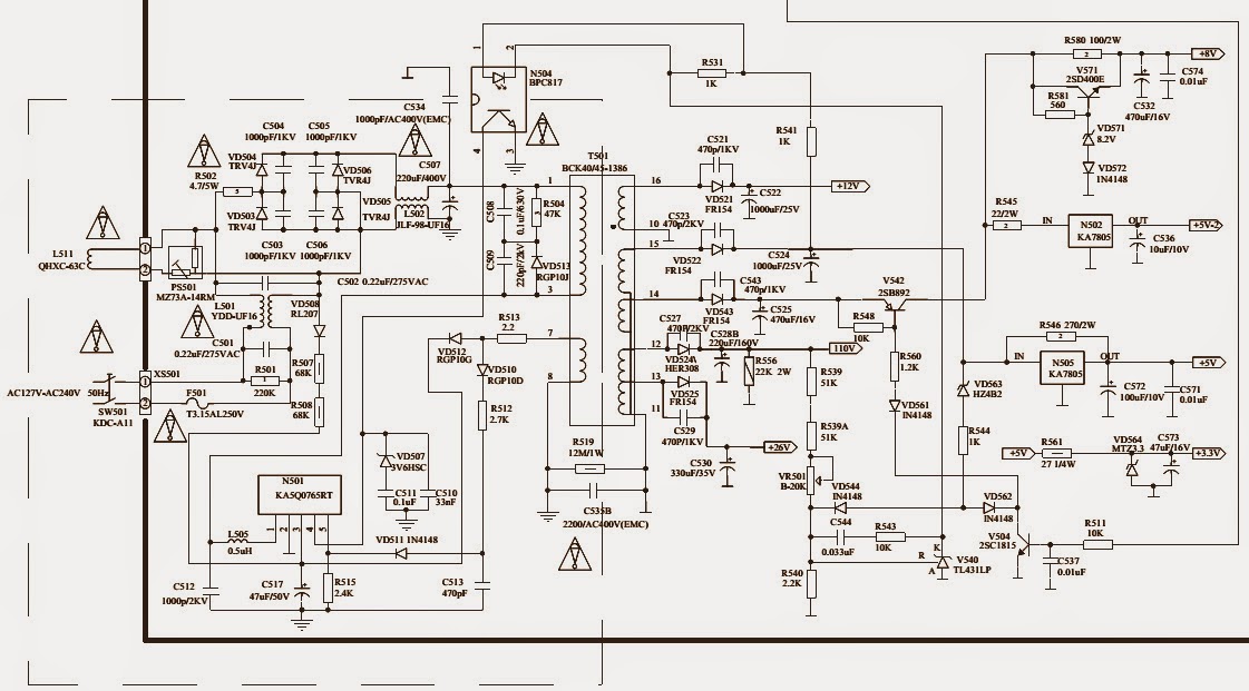
USED ICsPHILIPS UOC-KIT - TDA9341PS / N3 / A (TDA9341-EA3M (P070718) _ Memory - AT24C08A _SMPS - 5Q1265RF / CQ1265RF _ TR Chopper - BCK43-70120 / QC06001017463 BCK40-1829A (BCK40-45 / 1829A) _ SAW- F38.9H  _ Vertical - LA78041 / STV9302B _ Sound - AN17821A / AN17823A
Models - 37CTV3060, 37CTV3062, 37CTV3065, 37CTV3068, 37CTV3260, 37CTV3262, 37CTV3265, 37CTV3268, 54CTV3070, 54CTV3078, 54CTV3162, 54CTV3165, 54CTV3265, 54CTV3270, 54CTV3358, 54CTV3365, 54CTV3360, 72CTV3060, 72CTV3062, 72CTV3068.
SMPS SCHEMATIC
FULL SCHEMATIC
CLICK ON THE SCHEMATIC TO MAGNIFY

KENWOOD KDV3241Y – KDV-MP4339 – KDV-MP5032 – FIRMWARE UPGRADE – SCHEMATIC

$
0
0
KDV3241Y – KDV-MP4339 – KDV-MP5032– FIRMWARE UPGRADE – SCHEMATIC - DVD Firmware upgrade - Main Board Circuit Diagram
MAIN FIRMWARE UPGRADE
Confirmation of version information* Change the Source of audio set to CD/DVD.  (Default: tuner)
* Turn power off using power key.
* Press power key for 5 sec. (After power on, continue pressing)
* After 5 sec, beep sound rings two times. Then version information would show up at display.
* In order to check version of MAIN/CD system, Press band key.
* The version of system for main & CD is displayed in sequence.
Upgrade Program reading
Insert update CD in ACC on state and then [READING > M_UPGRAD] is displayed in order.
Upgrade start
* In order to start upgrade, Press 1[ENTER] key.
Upgrade progress display* Upgrade is in progress now.  [Erase > Write > I-VRF > D-VRF]
Upgrade Completion* When Upgrade finished, the display shows up “DOWN OK”. After 3 seconds, the audio set is reset automatically.
Caution
If power is off on the way of upgrading firmware, the set can’t be recovered.  Therefore pay lots of attention for power not to be off.
DVD FIRMWARE UPGRADE METHOD
Insert update CD in ACC on state and then [READING > D_UPGRAD] is displayed in order.
In order to start upgrade, Press 1[ENTER] key
Upgrade is in progress now.  [Read > Erase > Write > Verify]
When Upgrade finished, the DVD module is reset automatically.
Power supply
It is sufficient only to supply power for upgrade.
* Connect yellow line (Battery) and red line (Ignition) to plus and minus terminal respectively.
* Jack is connected to the audio set via its shapes matched each other.
* We need power supply for operation of audio set (Voltage : 12~15V Current : Over 2A).  Before connection between set and power supply, adjust voltage level to 15V typically (It is okay up to 12V.).  Power Supply has a variety of shapes and capacity of voltage and current.
  Main board _ Schematic
CLICK ON THE SCHEMATIC TO MAGNIFY


HOW TO DISASSEMBLE SONY SUPER AUDIO CD PLAYER_SCD-XE597 - AEP & UK Model

$
0
0
SONY SUPER AUDIO CD PLAYER_SCD-XE597 - AEP & UK ModelHOW TO OPEN THE DISC TRAY WHEN POWER SWITCH TURNS OFF
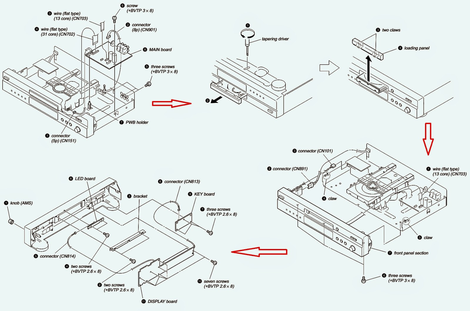
HOW TO DISASSEMBLE THE CD MECHANISM, MAIN BOARD,  LOADING PANEL, FRONT PANEL & KEYBOARD-DISPLAY BOARD
CD Mechanism Type - CDM66D-DVBU50
Optical Pick-up Name - DBU-3
HOW TO OPEN THE DISC TRAY WHEN POWER SWITCH TURNS OFF
* Insert a tapering driver into the aperture of the unit bottom, and turn in the direction of arrow.
* Use a flat (-) head screwdriver to open the disc tray by manual operation. (Flat head screwdriver with nominal blade length of 3mm.)
* To close the disc table, turn the driver in the reverse direction.
HOW TO DISASSEMBLE THE CD MECHANISM
MAIN BOARD, LOADING PANEL, FRONT PANEL & KEYBOARD-DISPLAY BOARD
TEST MODE
Setting Method of Test Mode
* Press three buttons ◄◄, [PUSH ENTER] and [POWER] simultaneously, The test mode becomes active. Then all segments of the fluorescent indicator tube are turned on.
FL Tube Grid, Segments Check
* Grid of all segments lights up sequentially starting from 1G to 16G.
* The vertical line (total 5 lines) of all grids lights up sequentially in the range of 5G to 16 G starting from the left.
* The horizontal line of (total 7 lines) of all grids lights up sequentially in the range of 5G to 16G starting from the top.
Sircs Receive Check
* The message “SIRCS CHECK” is displayed on the fluorescent indicator tube.
* With the machine in the status that is set in step 2, press any on the remote commander. The machine enters the key check standby state. (When the ► key or the Stop  key is pressed, the reception check is canceled.)
Key Check
* In the key check mode, the fluorescent indicator displays “KEY CHECK**”. Each time a button is pressed, “**” value.  However, once a button is pressed, it is no longer taken into account.
* To exit from this mode, the message “JOG CHECK” is displayed.
Jog Check
1. After the key check is completed, turn JOG clockwise to turn on the calendar segments sequentially. When the segment “15” is confirmed, turn JOG counter-clockwise that turns off the calendar segment. When the segment “1” is confirmed, this is the end of check.
Releasing Meted of Test Mode
* After all the checks are completed, confirm to see that the display “TEST-END” appears. The message indicates that the check is ended normally.
* Press the [POWER] button to turn off the main power and disconnect the power plug from the wall outlet.

MATRIX T7XE TREADMILL TROUBLESHOOTING - LED BLINKING CODES

$
0
0
ERROR CODES & ERROR MESSAGES _ TROUBLESHOOTING _ LED BLINKING CODES_ENTERTAINMENT TROUBLESHOOTING
REFERENCE DESIGNATOR & DESCRIPTION
LED 1 > Indicates the MCB with Daughter Board communication
LED 2 > Indicates the MCB with Daughter Board communication present
LED 3 > Indicates if MCB Voltage Supply is present.
ERROR CODES
Error messages - 0x01a2, 0x01a0, 0x0140, and 0x01a1.
Cause - incline direction is reversed.
* Check that the incline motor cable is connected at the MCB.
* Press "enter 2001 enter". The display should now read engineering mode.
* Press the calibration tab, then press start. If the calibration passes, delete the error log, unit is operational.
* If auto calibration fails, press manual cal elevation min and press start.
* Check to see if the led up and down lights are lit on the MCB as you change the elevation minimum. If leds are not lit, check the console cable and console. * If LEDs are lit, replace the incline motor.
* If incline motor does not resolve issues, replace MCB.
ERROR MESSAGE 0X02A0
1) cause - speed commanded but no belt movement detected (could be missing sensor).
2) Solution:
* Check the connection of the speed sensor cable to the MCB.
* Move the running belt, as it moves the MCB speed led should flash. If it does not, replace speed sensor.
* If the LED is flashing with belt movement, replace MCB signal wire
ERROR MESSAGES 0X02AE AND 0X02AF
1) Cause - checksum failure on critical novram loading (0X02AE) or checksum failure on non - critical novram loading (0X02AF).
2) Solution:
* Power the unit off / on.
* If the issue is not resolved by power reset, replace daughter board.
ERROR MESSAGE 0X029F
1) cause - error (drive fault report) created by the motor controller - used for ac motors only.
2) Solution:
* Power the unit off / on.
* Move the running belt, as it moves the MCB speed led should flash. if it does not, replace speed sensor.
* If the led is flashing with belt movement, replace MCB signal wire
ERROR MESSAGES 0X02B1 AND 0X02B2
1) Cause - the emergency circuit on the interface board fails (0x02b1) or the emergency circuit on the interface board active (0x02b2).
2) Solution:
* Check the emergency stop for function.
* If emergency stop is not working (always open or closed or a short), replace emergency stop switch.
* If emergency stop does not resolve the issue, replace the console.
ERROR MESSAGE 0X04A0
1) cause - the console's communication is lost
2) solution:
* Check the connection and condition of the digital communication wire at the daughter board.
* If no signal is present through the digital communication wire, led 1 on the daughter board should be unlit.
* Replace digital communication wire.
* Replace the daughter board.
ERROR MESSAGE 0X04A1
1) Cause - the motor control board's communication is lost.
2) Solution:
* Check the connection and condition of the MCB signal wire (goes from the daughter board to the MCB).
* If no signal is present through the MCB signal wire, led 2 on the daughter board should be unlit.
* Replace the MCB signal wire.
* Replace the daughter board.
ERROR MESSAGE 0X0441 AND 0X0442
1) Cause - a command is received from the console with its correct packet, but the daughter board has no function to support it (0x0441) or the received command code from the console is correct and is supported, but it has less or more data arguments.
2) Solution:
Power the unit off / on.
If the issue is not resolved by a power reset, replace daughter board
ERROR MESSAGE 0X0301
1) cause - flash or eeprom error.
2) Solution:
Power the unit off / on.
Replace the console
ERROR MESSAGE 0X3A5
1) Cause - failed to load the program.
2) Solution:
Reinstall the console software
ERROR MESSAGE 0X3A6
1) Cause - failed to run the program.
2) Solution:
Reinstall the console software.
ERROR BLINK CODES
ENTERTAINMENT TROUBLESHOOTING
Verify that your TV is Matrix brand equipment. Compare your TV to the TVs in Figures A and B. Compare your controller to Figure C. If your equipment looks different contact Matrix or the manufacturer of your TV equipment if known.
For Matrix produced and mounted equipment you can use the information outlined in this section to help with any connection and power issues you may have. If you have questions that are specific to the TV alone (settings, programming, menu options, etc) please see the entertainment owner’s manual.
PICTURE FUZZY OR UNCLEAR
Using a verified good piece of coax cable, remove the console back cover and hook the coax directly to the TV jack.  This bypasses internal connections for your machine.
Check your internal cables and fittings inside your machine at the console and below the motor cover. Make sure you have no damage (kinks, cuts etc) and no stray wires or poor fittings on the ends of the cables. Fittings should look clean  connector and no stray aluminium strands touching the centre conductor. Replace or repair any suspected cables.
If no damage can be found on cables, fittings, or connectors begin replacing cables and connectors with known good parts until the damaged part is found.
TV WILL NOT TURN ON
If you have no picture at all, check to see if you have any status lights on your controller (controller light is next to power button).  The status light should be red when off or in standby mode, and green when the TV is powered on.
Remove the console back (Figure A) and check the electrical connections for the TV
After you have verified all connections are secure and problem still exists verify power at the outlet. If outlet is not outputting 120 volts, check  room power.
If internal electrical connections are good,, and the outlet is outputting 120 Volts, the issue is likely with the TV, contact Matrix.
CONTROLLER ISSUES
If you have a status light on the controller but the On/Off button gives no response, disconnect and then reconnect the power to the treadmill from the wall. Attempt to turn on the TV again using the On/Off button.
If TV still does not power on, remove the console back  and check the controller connections at the console.
If the TV does not power on after the controller connections are reset, the issue it is likely with the TV itself, contact Matrix.

TCL LCD TV - POWER and BACK-LIGHT INVERTER BOARD - SCHEMATIC

$
0
0
SCH PH24A - Power & Back-light Inverter board _ Circuit Diagram
SMPS 

BACK-LIGHT INVERTER
CLICK ON THE SCHEMATIC TO ZOOM IN

SAMSUNG PDP-HPT50 - PLASMA DISPLAY TROUBLESHOOTING - URC SET-UP CODES

$
0
0
Samsung PDP-HPT50 Plasma Display _ Troubleshooting _ Universal Remote Control Set-up Codes
DRIVE BOARD TROUBLESHOOTING CHART
ABNORMAL DISPLAY
Abnormal Display is related with Y-MAIN, X-MAIN, Logic Main and so on.  This page shows you how to check the boards, and the following pictures show you how to find the defective board.
ADDRESS OPEN _ SHORT
SUSTAIN OPEN-SHORT
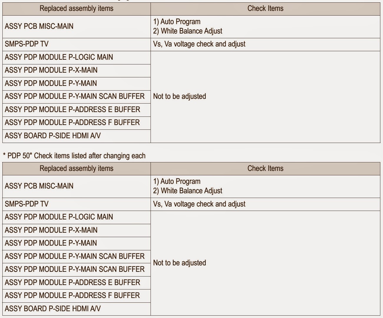
TROUBLESHOOTING PROCEDURE CHART BY ASSEMBLY
CLICK ON THE PICTURES TO MAGNIFY
Universal Remote Control Set-up Codes to check with Samsung Brand TVs
0030 0049 0050 0066 0076 0101 0102 0119 0143 0152 0154 0166 0181 0195 0209 0217 0240 0307 0318 0365 0379 0414 0421 0488 0492 0601 0624 0637 0642 0827

HPT4264X _ HPT5064X - SAMSUNG Calla - PLASMA DISPLAY TV – Service Mode Adjustments _ Calibration

$
0
0
Samsung Calla - PLASMA DISPLAY TV – Service Mode Adjustments _ Calibration
COLOR CALIBRATION [AV]
1 Apply the NTSC Lattice (N0. 3) pattern signal to the AV IN 1 port
2 Press the Source key to switch to "AV1" mode
3 Enter Service mode
4 Select the "Calibration" menu
5 Select the "AV Calibration" menu.
6 In "AV Calibration Off" status, press the "
" key to perform Calibration.
7 When Calibration is complete, it returns to the high-level menu.
8 You can see the change of the "AV Calibration" status from Failure to Success.
COLOR CALIBRATION [COMPONENT]
1 Apply the 720p Lattice (N0. 6) pattern signal to the Component IN 1 port
2 Press the Source key to switch to "Component1" mode
3 Enter Service mode
4 Select the "Calibration" menu
5 Select the "Comp Calibration" menu.
6 In "Comp Calibration Off" status, press the "
" key to perform Calibration.
7 When Calibration is complete, it returns to the high-level menu.
8 You can see the change of the "Comp Calibration" status from Failure to Success.
COLOR CALIBRATION [PC]
1 Apply the VESA XGA Lattice (N0. 21) pattern signal to the PC IN port
2 Press the Source key to switch to "PC" mode
3 Enter Service mode
4 Select the "Calibration" menu
5 Select the "PC Calibration" menu.
6 In "PC Calibration Off" status, press the "
" key to perform Calibration.
7 When Calibration is complete, it returns to the high-level menu.
8 You can see the change of the "PC Calibration" status from Failure to Success.
COLOR CALIBRATION [HDMI]
1 Apply the 720p Lattice (N0. 6) pattern signal to the HDMI1/DVI IN port
2 Press the Source key to switch to "HDMI1" mode
3 Enter Service mode
4 Select the "Calibration" menu
5 Select the "HDMI Calibration" menu.
6 In "HDMI Calibration Off" status, press the "
" key to perform Calibration.
7 When Calibration is complete, it returns to the high-level menu.
8 You can see the change of the "HDMI Calibration" status from Failure to Success.
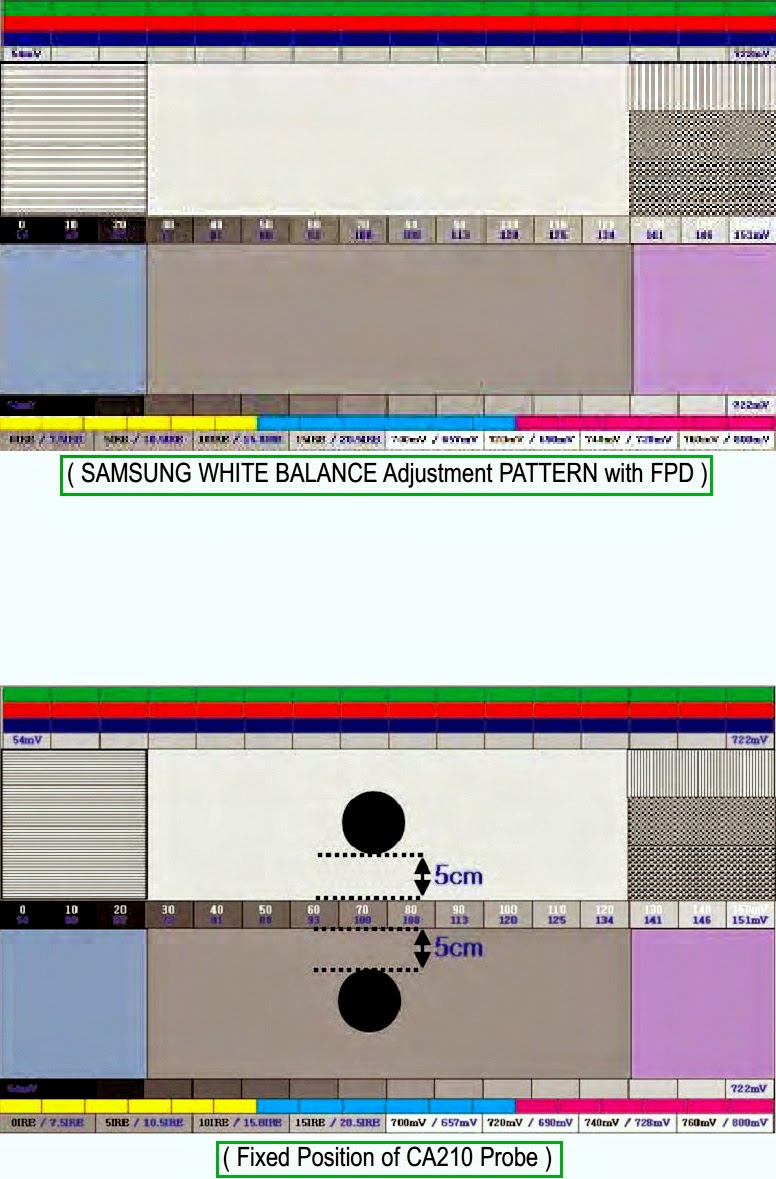
WHITE BALANCE ADJUSTMENT
1. Source : HDMI
2. Setting Mode : 1280*720@60Hz
3. Pattern : Pattern #92
4. Use Equipment : MIK-7256 (MSPG925L)
WORK ORDER
* Connect HDMI (DVI) output terminal of MIK-7256 (MSPG925L) to the HDMI input in main set
* Set the input to HDMI mode
* Enter the White Balance menu of service mode
* Contact CA-210 sensor to glass filter.
Adjust the low light
Adjust Sub-Bright (LBE) to set the 'Y' value
Adjust R-Offset ('x') and B-Offset ('y') to the color coordinates.
Do not adjust G-Offset data.
Adjust the high light.
Adjust Sub-Contrast (LBE) to set the 'Y' value
Adjust R-Gain ('x') and B-Gain ('y') to the color coordinates.
Do not adjust the G-gain data.
REPLACEMENT & CALIBRATION
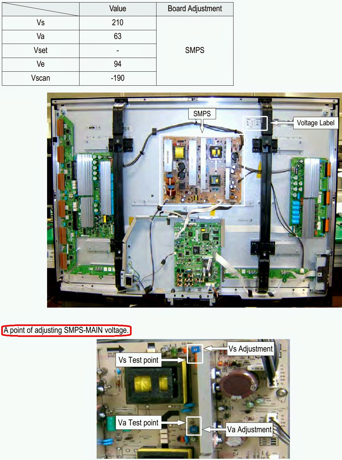
When replacing the SMPS or PDP panel, you have to check the voltage printed on the panel sticker and adjust it.
VOLTAGE ADJUSTMENT
After replacing the SMPS or PDP panel, you must adjust the voltage referring to the voltage label printed on the panel.  (If you do not adjust the voltage, an abnormal discharge symptom may appear.)
Point of adjusting SMPS-MAIN voltage.
FIRMWARE UPGRADE
USB Download Method
1. Copy the Upgrade Files into the path "
callaus" in USB flash driver.
2. USB Download
* Insert the USB Memory Stick to the WISELINK port in Stand-by mode.
* Turn the power on.
* Press "MENU" and find "SW Upgrade" in Menu "SETUP".
* Select the "SW Upgrade" from the menu.
* Select "USB" from the menu.
* The banner OSD "Scaning for USB..." is displayed.
* The banner OSD "Upgrade version **** to version ****" is displayed.Select "Yes".
* The banner OSD "Upgrade version **** to version ****" is displayed. It takes about 30 sec.  (Warning: Don't remove USB flash driver during upgrade.)
* The banner OSD "Upgrade is completed" is displayed when the upgrade is completed.
* Remove the USB flash driver from PDP TV and check the program version.
How to Check the Version of the Program
1. Procedures for checking in the User Menu
* Select the "Setup" menu in the Menu screen
* Place the cursor over the "On" of "Function Help", and press the "Info" key on the remote control
* The version of the program is displayed at the bottom of the Menu screen.
SERVICE MODE
How to Access Service Mode
Settings when entering Factory mode
Sharp Screen (Dynamic), Color Tone (Cool 1), Factory (Dynamic CE Off), DNIe(Off)
Adjustment Procedures
> Channel 
▲/▼ Key : Select an item.
> Volume ◀/▶ Key : Adjust the value up or down.
> MENU Key : Save the changes to the EEPROM and return to the higher-level mode.
> Using the Numeric (
0~9) keys, you can select a channel.
> Using the SOURCE key, you can switch AV modes.
The version of the firmware displayed at the bottom of the screen may differ and the firmware is subject to change for the improvement of product functions.* If you have adjusted the settings in Service Mode, you have to reset the product.
* If you exit Service Mode without reset, DNIe value keeps Off regardless of setting up the user.

SONY HCD-SH2000 - HOW TO DISASSEMBLE THE CD MECHANISM

$
0
0
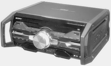
SONY HCD-SH2000 is the tuner, USB, CD and amplifier section in FST-SH2000/LBT-SH2000. 
MINI HI-FI COMPONENT SYSTEM
Optical Pick-up Name > KHM-313CAB/C2N
CD Mechanism Type > CDM86B-DVBU101
HOW TO EJECT THE DISC IN EMERGENCY
Take out the CD mechanism block from a set.  Procedure given
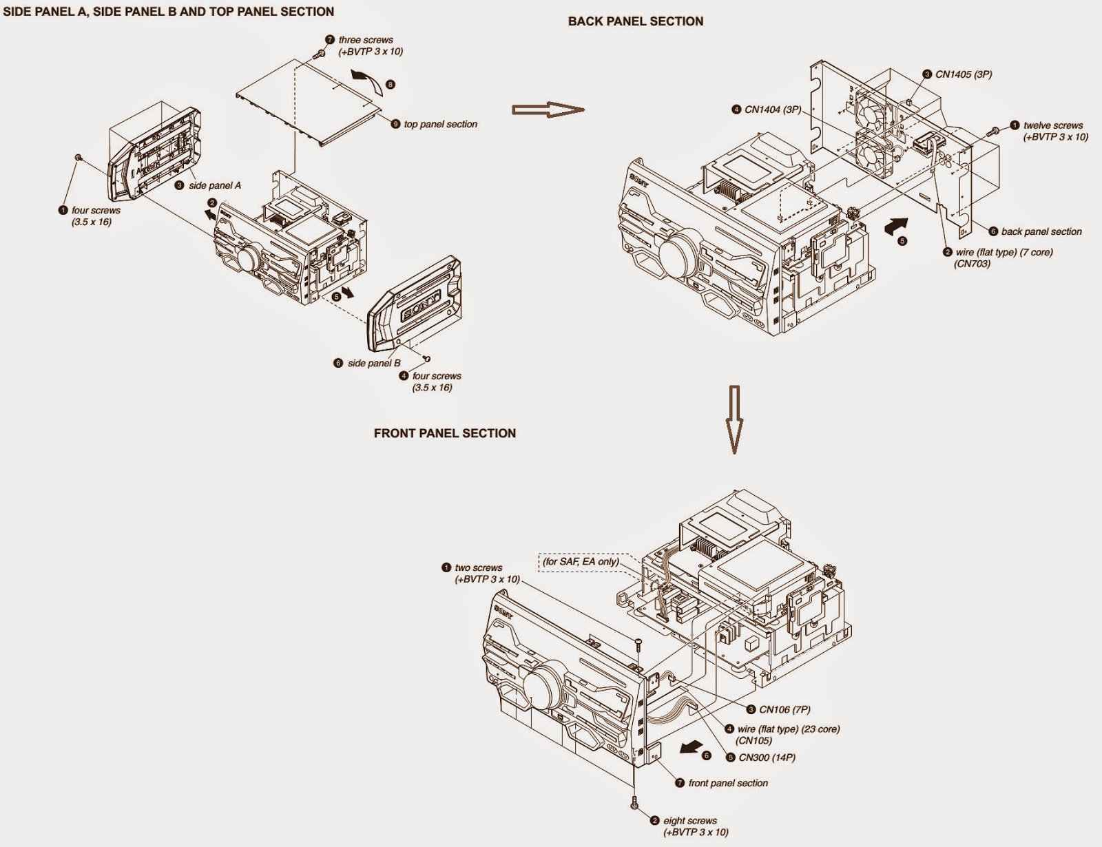
DISASSEMBLY
CLICK ON THE PICTURES TO MAGNIFY

MINI HI-FI COMPONENT SYSTEM - SONY HCD SH2000 - Factory Reset – Cold reset – Panel Test

$
0
0
FACTORY RESET
This mode is use to load all the factory use preset frequencies into FM 1-FM 20 and AM 1-AM 10. Originally, frequency of FM 1-FM 20 and AM 1-AM10 are set to the minimum frequency.
1 Press the Power  button to turn on the system.
2 Press [SEARCH] button and [TUNER/BAND] button simultaneously and hold for 3 seconds, message “FACTORY” appears on the fluorescent indicator tube. The function is changed to TUNER automatically.
CD SHIP MODE (WITH MEMORY CLEAR)
This mode moves the optical pick-up to the position durable to vibration and clears all data including preset data stored in the data flash to initial conditions during the next AC-In. Use this mode when returning the set to the customer after repair.
1 Press the Power button to turn on the system.
2 Select CD function and without disc inserted.
3 Press [EJECT] button and the Power button simultaneously for 3 seconds. The system turns off automatically.
4 A message “MECHA LOCK” is displayed on the fluorescent indicator tube and the CD ship mode is set.
COLD RESET
The cold reset clears all data including preset data stored in the EEPROM to initial conditions. Execute this mode when returning the set to the customer.
1 Press the Power button to turn on the system.
2 Press the Stop & Power button simultaneously for 3 seconds.
3“COLD RESET” appears on the fluorescent indicator tube.  After that, the fluorescent indicator tube becomes blank for a while, and the system is reset.
PANEL TEST MODE
This mode is used to check the fluorescent indicator tube, LEDs, keys, [MASTER VOLUME] jog, model, destination and software version.
1 Press [SEARCH] button and [OPTIONS] button simultaneously and hold 3 seconds.
2 All LEDs and segments in fluorescent indicator tube will light up.
3 When you want to enter to the software version display mode, press [FLANGER] button. The model information appears on the fluorescent indicator tube. Press [FLANGER] button again to view the destination information.
4 During the destination information display, press [FLANGER] button. Each time [FLANGER] button is pressed, the fluorescent indicator tube shows the version of each category software in the following sequence: SC, MTK (DMB Board firmware version), UI, PF, SYS, CD, CDMA, CDMB, ST, TA, TAS, TM and return back to model information display.
5 When [SEARCH] button is pressed while the version numbers are being displayed except model and destination, the date of the software creation appears. When [SEARCH] button is pressed again, the display returns to the software version display.
6 Press [ISOLATOR] button, the key check mode is activated.
7 In the key check mode, the fluorescent indicator tube displays “K 0 V0”. Each time a button is pressed, “K” value increases.  However, once a button has been pressed, it is no longer taken into account.  “V” value increases in the manner of 0, 1, 2, 3 ... if [MASTER VOLUME] knob is turned clockwise, or it decreases in the manner of 0, 9, 8, 7 ... if [MASTER VOLUME] knob is turned ccounter-clockwise
8 When [SOUND FLASH] button is pressed after all LEDs and segments in fluorescent indicator tube light up, alternate segments in fluorescent indicator tube and LEDs would light up. If you press [SOUND FLASH] button again, another half of alternate segments in fluorescent indicator tube and LEDs would light up. Pressing [SOUND FLASH] button again would cause all segments in fluorescent indicator tube and LEDs light OFF. Pressing [SOUND FLASH] button again would cause all segments in fluorescent indicator tube and all LEDs light up.
9 To release from this mode, press the [SEARCH] button and [OPTIONS] button in the same manner as step 1, or disconnect the power cord.
COMMON TEST MODE
This mode is used to check operations of the Amplifier section.
To enter Common Test Mode
1 Press [USB/USB SELECT] button and [PRESET EQ] button simultaneously and hold for 3 seconds.
2 The upper segments of fluorescent indicator tube will blink.  The function is changed to TV and the volume is changed to VOLUME MIN.
Check of Amplifier
1 Press [PRESET EQ] button repeatedly until a message “GEQ MAX” appears on the fluorescent indicator tube. GEQ increases to its maximum.
2 Press [PRESET EQ] button repeatedly until a message “GEQ MIN” appears on the fluorescent indicator tube. GEQ decreases to its minimum.
3 Press [PRESET EQ] button repeatedly until a message “GEQ FLAT” appears on the fluorescent indicator tube. GEQ is set to fl at.
4 When the [MASTER VOLUME] knob is turned clockwise even slightly, the sound volume increases to its maximum and a message “VOLUME MAX” appears on the fluorescent indicator tube.
5 When the [MASTER VOLUME] knob is turned counterclockwise even slightly, the sound volume decreases to its minimum and a message “VOLUME MIN” appears on the fluorescent indicator tube.
To release from Common Test mode
1 To release from this mode, press Power button.
2 The cold reset is enforced at the same time.
TUNER STEP CHANGE
The step interval of AM channels can be toggled between 9 kHz and 10 kHz. This mode is not available for Saudi Arabian, European and Russian models.
1 Press the Power button to turn on the system.
2 Press [FUNCTION] button repeatedly to select the “AM”.
3 Press the Power  button to turn off the system.
4 Press [ENTER] button and the Powerbutton simultaneously. The system turns on automatically. The message “AM 9K STEP” or “AM 10K STEP” appears on the fluorescent indicator tube and thus the channel step is changed.
CD SHIP MODE (WITHOUT MEMORY CLEAR)
This mode moves the optical pick-up to the position durable to vibration. Use this mode when returning the set to the customer after repair.
5 Press the Power button to turn on the system.
6 Select CD function and without disc inserted.
7 Press [CD] button and the Power button simultaneously. The system turns off automatically.
8 A message “MECHA LOCK” is displayed on the fluorescent indicator tube and the CD ship mode is set.
DISC THEFT PREVENTION MODE
This mode let prevent disc to be ejected. When this mode is activated, the disc will not eject when [EJECT] button is pressed.  The message “LOCKED” will be displayed on the fluorescent indicator tube. This mode only applied when there is disc.
1 Press the Power
button to turn on the system.
2 Select CD function.
3 Press [PLAY/PAUSE] button and [EJECT] button simultaneously for 3 seconds. The message “LOCKED” or “UNLOCKED” displayed on the fluorescent indicator tube.


HOW TO SET LANGUAGE TO CANON PRINTER NP6035 – NP6028 – NP6230

$
0
0
SERVICE MODE & Language Selection_ CANON PRINTER NP6035 – NP6028 – NP6230
SERVICE MODE
To select the language, you have to enter its service mode option.
The NP6035’s service mode is classified into the following six: Under each of the modes are items.
Using the Service Mode.
 Open the front door, and insert the door switch actuator. If you want to make checks under I/O display mode while making copies, set the appropriate copying mode.
* Open the front door, and insert the door switch actuator. If you want to make checks under I/O display mode while making copies, set the appropriate copying mode. Press the service mode switch (SW3) with a hex key.
* Press the service mode switch [SW3] with a hex key.
* The copier will indicate “ $” in the upper left corner of the message display when it has started the service mode.
* Press the “ *“ key twice.  The copier will show the service initial screen.
* Select the appropriate mode on the screen.
* Using the ►►/◄◄ key, select the appropriate screen.
* Make the appropriate check or adjustment.
To end the service mode:
> Press the reset key [ // ] once to leave the current mode.
> Press the reset key once again to end the service mode.
 The copier ends service mode when you turn off the power switch or disconnected the power plug.  However, opening the front door, right door, delivery door, pedestal right door or pedestal left door will not end the service mode.
Service mode key position
Using Adjustment Mode and Options Mode
 Using adjustment mode or options mode, you can store the settings made on the control panel in the RAM on the DC controller, thereby simulating the functions of the conventional VRs and SWs.
 Each machine is adjusted at the factory, and the effective adjustment values are recorded on the label.
 If you have replaced the DC controller PCB or initialized the RAM, you must enter the values recorded on the label and the drum label attached to the front of the drum unit. Further, you must always record any values you entered newly in the field.
LANGUAGE SELECTION
Control Display Mode (* 1 *): Using the ►►/◄◄  key, select the following screens.
CLICK ON THE PICTURES TO ZOOM IN

PANASONIC SMC-KM40205877C3 - TELEPHONE - SCHEMATIC - LOCK - UNLOCK

$
0
0
Circuit Diagram _ Lock _ Unlock _ Panasonic Telephone [Table model] - SMC-KM40205877C3
BUTTON FUNCTIONS
MAIN BOARD SCHEMATIC
MAIN BOARD - BOTTOM VIEW
KEYBOARD SCHEMATIC
KEYBOARD - BOTTOM VIEW
ELECTRONIC LOCK & UNLOCK PROCEDURE
CLICK ON THE PICTURES TO MAGNIFY

SANYO SW-7010T - SANYO SW-7010TP - DISASSEMBLE - SPARE PART LIST - Wiring Diagram

$
0
0
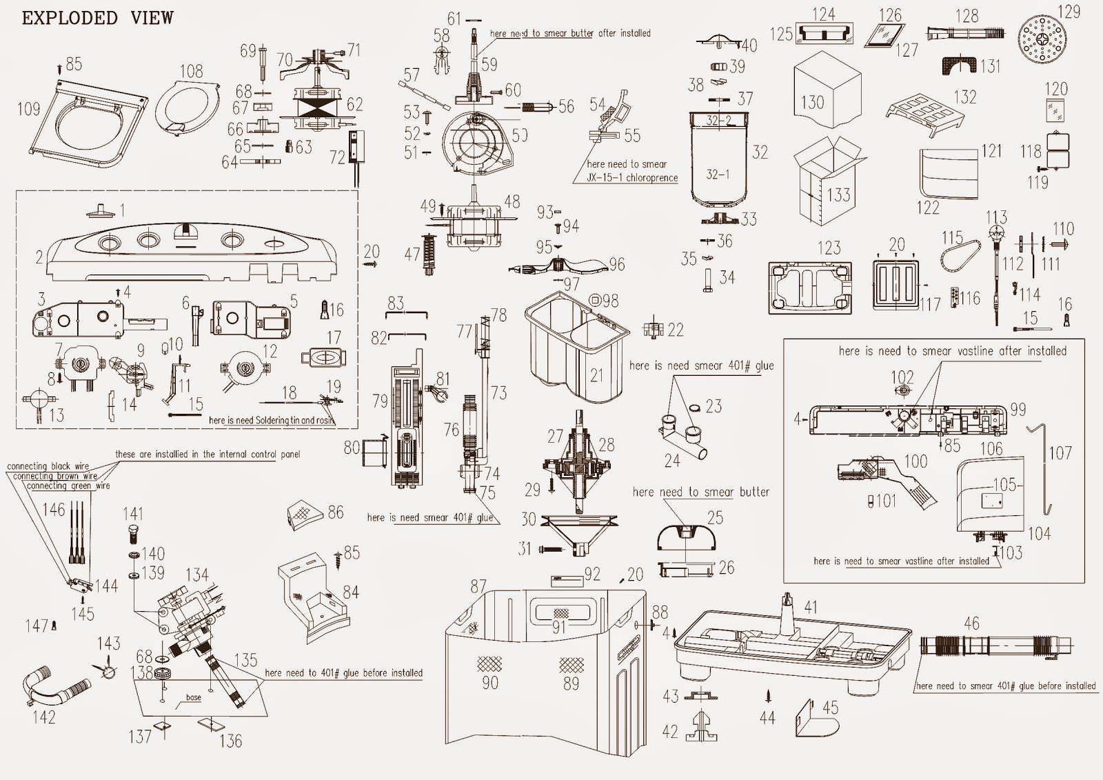
Exploded View _ Part list _ Wiring Diagram
Sanyo SW-7010T - SW-7010TP- Twin Tub Washing Machine
WIRING DIAGRAM
PARTS LIST & EXPLODED VIEW
* Un-plug the machine to prevent possible electrical shock when the washer is repaired.
* When a washing motor is rotating, a fan of the main body of a small pulley cannot be seen. When you touch your hand to the fan by accident, you may get hurt.
* Start to repair the washer after it stops completely.
CLICK ON THE PICTURES TO MAGNIFY

RICOH GXE3300N - GXE770N - GX7000 - PRINTER ADJUSTMENTS

$
0
0
Ricoh GX e3300N - Ricoh GX e7700N - Ricoh GX7000Adjustment _ Line Fault _ Paper feed adjustment.
PAPER FEED ADJUSTMENT
If horizontal lines are printed unaligned, print images are patchy, or a black or white line is printed at regular intervals, print a test pattern, and then adjust the paper feed setting.
* Slide the envelope selector to the forward position.
* Press the [Menu] key.
* Press the [UP] or [DN] key to display [Maintenance], and then press the [Enter] key. [M e n u : M a i n t e n a n c e]
* Press the [UP ] or [DN] key to display [Adj.Paper Feed], and then press the [Enter] key.  [M a i n t e n a n c e : A d j . P a p e r F e e d]
* Press the [UP ] or [DN ] key to display [Pr.Test Pattern], and then press the [Enter] key. [A d j . P a p e r F e e d : P r . T e s t P a t t e r n]

* Check the optimal adjustment values on the printed test pattern.  The optimal adjustment value is the number that appears on the left of the lightest gray square with straight horizontal lines on both sides. When this number is “+2”, the optimal adjustment value is “+2”.
When horizontal lines beside the lightest grey square are broken, select the optimal adjustment value by referring to the lines broken in the opposite direction. When the “+2” square is the lightest grey square and the “+6” horizontal lines are broken in the opposite direction, the optimal adjustment value is between “+3” and “+5”. After adjustment, check the adjustment result.
* Press the [UP] or [DN] key to display [Adjustment], and then press the [Enter] key. [A d j . P a p e r F e e d : A d j u s t m e n t]
* Press the [UP] or [DN] key to enter the adjustment value (-14 to +14) from step 6, and then press the [Enter] key. [A :( - 1 4 , + 1 4 ) 0.
* Press the [Online] key.  The initial screen appears.
Head Position Adjustment
* Slide the envelope selector to the forward position.
* Press the [Menu] key.
* Press the [UP] or [DN] key to display [Maintenance], and then press the [Enter] key. [M e n u : M a i n t e n a n c e]
* Press the [UP] or [DN] key to display [Head Position], and then press the [Enter] key. [M a i n t e n a n c e : H e a d P o s i t i o n]
* Press the [UP] or [DN] key to display [Pr.Test Pattern], and then press the [Enter] key.  [A d j . P a p e r F e e d : P r . T e s t P a t t e r n]
* Press the [UP] or [DN] key to select a test pattern, and then press the [Enter] key. [P r . T e s t P a t t e r n : H i g h Q u a l i t y]
To adjust print-head positions for all resolutions, repeat this procedure selecting the other resolution.  NOTE: A test pattern to adjust print-head positions is printed.
* Press the [UP] or [DN] key to select a test pattern, and then press the [Enter]
key.
* Press the [UP ] or [DN] key to display [Adjustment], and then press the [Enter] key.
* Press the [UP ] or [DN] key to select a resolution from step 6, and then press the [Enter] key. [A d j u s t m e n t : H i g h Q u a l i t y]
* Press the [UP] or [DN] key to select a line, and then press the [Enter] key. [A d j u s t m e n t : 1 . A]
* Enter the optimal adjustment values from step 7, and then press the [Enter] key. [A : ( - 4 , + 4 ) 0.
* Press the [Online] key.  The initial screen appears.


CANON PIXMA iP4200 Printer - Error display _ Service Call Errors _ Fault Indications [LED]

$
0
0
Error display _ Service call errors _ Fault Indications [LED] _ CANON - PIXMA iP4200

ERROR DISPLAYs
Errors are indicated by the LED, and warnings are displayed on the monitor of the computer connected to the printer.
Operator Call Errors (by Alarm LED Blinking in Orange)
Service Call Errors (by Cyclic Blinking in Orange (Alarm LED) and Green (Power LED), or Alarm LED Lit in Orange)
Before replacement of the logic board ass'y, check the waste ink amount (by service test print or EEPROM information print). If the waste ink amount is 7% or more, also replace the ink absorber kit (QY5-0146) when replacing the logic board ass'y
Printer (no LED indications) & Troubleshooting by Symptom
CLICK ON THE TABLES TO ZOOM IN

Viewing all 2033 articles
Browse latest View live