Quantcast
Channel: Electro help
Viewing all 2033 articles
Browse latest View live

VESTEL 17PS15-4 - 16” – 19” – 22” - LCD Integrated Power Supply – 17ps15-4 - Schematic

$
0
0
16”–19”–22”_ LCD Integrated Power Supply – 17ps15-4 - Schematic VESTEL
CIRCUIT DIAGRAM - SMPS & INVERTER {Click on the Circuit Diagrams to Magnify}
INVERTER


INFINITY PRIMUS - SUB-WOOFER - SCHEMATIC

$
0
0
Schematic & Exploded View - Infinity SUB-100
EXPLODED VIEW
SCHEMATICS - POWER AMP - POWER SUPPLY & PRE-AMP
CLICK ON THE PICTURES TO ZOOM IN


INFINITY MODULUS Sub Amplifier - Sub-100 HTS - Repair HELP

$
0
0
Exploded View _ Circuit Diagram _ Infinity Modulus Home Theater System _ HTS SUB-100
SPECIFICATIONS
Center Channel
Frequency Range: 80Hz - 20,000Hz (+/-3dB)
Recommended Amplifier Power: 15 - 125 watts Sensitivity (2,83 V @ 1m) 88dB
Nominal Impedance: 8 Ohms
Crossover Frequency: 2500Hz, 12dB/Octave
Midrange Driver
Dual 100mm C.M.M.D., magnetically shielded
High-Frequency Driver
19mm C.M.M.D., magnetically shielded
Dimensions (H x W x D): 159mm x 527mm x 114mm
Weight: 3.6kg.
Subwoofer
Frequency Range: 35Hz - 100Hz (+/-3dB)
Amplifier Power Output: 110 watts
Low-Frequency Driver: 250mm C.M.M.D., magnetically shielded
Crossover Frequency: variable 40-130Hz, detent at 100Hz
Dimensions (H x W x D): 369mm x 349mm x 414mm
Weight: 15.5kg.
Satellite
Frequency Range: 100Hz - 20,000Hz (+/-3db)
Recommended Amplifier Power: 15 - 125 watts
Sensitivity: 86dB
Nominal Impedance: 8 Ohms
Crossover Frequency: 2500Hz, 12dB/Octave
Midrange Driver
100mm C.M.M.D., magnetically shielded
High-Frequency Driver
19mm C.M.M.D., magnetically shielded
Dimensions (H x W x D): Shelf Position: 279mm x 140mm x 114mm
Wall Position: 248mm x 140mm x 146mm
Weight: 2.3kg.
EXPLODED VIEW & WIRING DIAGRAM: SUB-WOOFER
TO SERVICE THE MODULUS MCC-1 CENTER
1 Remove the grille.
2 Remove the (7) exposed rubber grille retainers; this can be accomplished by carefully pulling them out of their cavities with long-nosed pliers or similar tool.
3 Remove the (7) Phillips screws that are now exposed.
4 Four additional screws lie underneath the two front trim panels; these can be carefully removed by applying a blow dryer (high or maximum) or heat gun to the trim panels. Take care not to direct the gun directly at the woofer or tweeter; do not burn yourself after each panel has been heated – gloves are recommended. See illustration.  If either trim panel is damaged upon removal, order:
 MODCTRPLATE-L – Left Trim Panel
 MODCTRPLATE-R – Right Trim Panel
5 Remove the (4) additional Phillips screws that are now exposed.
6 Carefully lift the front baffle, with drivers attached, off the cabinet.
7 Reassembly: Adhesive already in place, if encrusted on the front baffle, must be removed by scraping it off as it may prevent the trim panel from sitting flush on the front baffle. New adhesive must be added to reattach the trim panel.
TO SERVICE THE MODULUS MS-1 SATELLITE
1 Remove the grille.
2 Remove the (4) exposed rubber grille retainers; this can be accomplished by carefully pulling them out of their cavities with long-nosed pliers or similar tool.
3 Remove the (4) Phillips screws that are now exposed.
4 Two additional screws lie underneath the front trim panel; this can be carefully removed by applying a blow dryer (high or maximum) or heat gun to the trim panel. Take care not to direct the gun directly at the woofer or tweeter; do not burn yourself after the panel has been heated – gloves are recommended. See illustration.  If this trim panel is damaged upon removal, order:
 MODSATDECCHAR (Charcoal)
 MODSATDECPLAT (Platinum)
5 Remove the (2) additional Phillips screws that are now exposed.
6 Carefully lift the front baffle, with drivers attached, off the cabinet.
7 Reassembly: Adhesive already in place, if encrusted on the front baffle, must be removed by scraping it off as it may prevent the trim panel from sitting flush on the front baffle. New adhesive must be added to reattach the trim panel.
CIRCUIT DIAGRAM
CLICK ON THE PICTURES TO MAGNIFY

SAMSUNG PN50C450B1 - POWER SUPPLY [SMPS] TROUBLESHOOTING

$
0
0
Firmware: Check Samsung.com for latest update - 3/16/11 IMPORTANT -T-SAT4AUSHC(1008.2 or 1008.3).EXE
You should check serial number and bulletin before updating firmware.
Reason: Red Dot issue.  Buzzing noise level will be reduced.
POWER SUPPLY TROUBLESHOOTING
Activating Power & Logic Board test patterns without main board.
* Remove the power cord to panel.
* Short the Highest two pins on the logic board.
* Remove the power connection at the main main board; keeping connection to SMPS. Short the  Power ON pin to circuit ground on power connector to SMPS.
* Connect the power cord to panel.
2010/2011 models
Will not be run with the “X” or “Y” main disconnected. The SMPS will shut down immediately. However if a meter is first connected to the test point when power is applied it will read the correct voltage briefly before shutting down.(You have enough time to check key voltages).  CAUTION: Do not reconnect any connectors to SMPS or Y/X Boards until power has been turned off long enough for Vs to drop below 10V or damage will occur to X or Y Boards.
Over Current Protection
  For the SMPS Power Supply... If a short circuit occurs on either the VS or VA voltage lines, the SMPS stops operating, but should not fail. When the short circuit is removed from the source line, the Power Supply will operate normally again. Many SMPS Supplies are replaced needlessly.
  When troubleshooting, It’s very important to first check Vs, Va, Vsc & Ve If Vs is missing (0V), disconnect power and check for short. Use ohm meter to measure resistance while disconnecting Y-Board & X-Board supply feeds one at a time.  Turn Power On and Test SMPS with short connector removed for correct Vs voltage verification. (It may only come up briefly but to full level). Again be careful not to reconnect Power Connectors until Vs falls below 10V.
  If Va is low or missing, disconnect Supply Feed to Address Boards and Check to see if SMPS Supply is restored. (Note Va feed normally passes through the Y-Drive to the Address Boards (Logic Buffer Boards). 
  If Vsc is low or missing and Vs was OK, the failure is with the Y-Board since the Y-Board generate the Vsc voltage from the Vs supplied by the SMPS.
  If Ve is low or missing and Vs is OK, the failure is with the X-Board since the Ve is generated by the X-Board from the Vs supplied by the SMPS. Please note in some rare cases the Ve may be generated by the Y-Board feed to the XBoard.)
Other SMPS Voltages:
Check Low Voltage feeds to the Main Board and other supplied Assemblies.
CLICK ON THE PICTURES TO ZOOM IN

PN50C450B1DXZA - SAMSUNG PLASMA DISPLAY - SERVICE MODE - VIDEO PROBLEMS - TROUBLESHOOTING.

$
0
0
Logic board_Logic buffer board_Y board_Y-buffer board _ X-board & Main Board failure symptoms.
Almost all Plasma Displays will exhibit the similar symptoms as give below; irrespective of its Brand name and Model number.
Universal remote control set-up codes
VIDEO PROBLEMS
Verify Video Operation
# Customer Picture Test (if available)
# “Display” (If display is OK source is suspected)
# Using Test Patterns in Service Mode.
 ENTERING SERVICE MODE
Customer Remote:  Power off > Mute > 182 > Power.
Service Remote: Power On > Info, Factory.
2010 PDP signal path for troubleshooting.
To Determine the cause
* If Logic pattern is NG; Logic board, Logic buffers or Panel are suspect.
* If FBE patterns is NG and Logic is OK; Main or LVDS cable are suspect.
* If both are OK it is likely a source issue.
Y-board failure examples.
Y buffer board failure examples.
Logic board failure examples.
Logic buffer board failure examples.
X board failure examples
Main board failure
Boards & part numbers
Universal remote control set-up codes, to check with Samsung Brand TVs [For All Types]
0030 0049 0050 0066 0076 0101 0102 0119 0143 0152 0154 0166 0181 0195 0209 0217 0240 0307 0318 0365 0379 0414 0421 0488 0492 0601 0624 0637 0642 0827
CLICK ON THE PICTURES TO ZOOM IN

HOW TO ENTER SERVICE MODE - PANASONIC PLASMA TV - PN50C450B1DXZC

$
0
0
Panasonic Plasma TV - PN50C450B1DXZC–  Service Mode – Fault Symptoms and Suspected-able Board Assemblies.
FAULT SYMPTOMS & PROBABLE CIRCUIT BOARD ASSEMBLIES
SMPS-PDP TV > No power, Blank screen, the Relay repeats On and Off
ASSY PDP P-X-MAIN BOARD> Blank screen
ASSY PDP P-Y-MAIN BOARD> Blank screen
ASSY PDP P-LOGIC MAIN BOARD> Blank screen, Screen noise
ASSY PDP P-X-MAIN BUFFER BOARD> Upper screen is blank
ASSY PDP P-Y-MAIN BUFFER BOARD> Lower screen is blank
ASSY PDP P-E-BUFFER BOARD> Corresponding Buffer Board block screen is blank
ASSY PDP P-F-BUFFER BOARD> Corresponding Buffer Board block screen is blank
ASSY PCB MISC-MAIN> No Power, Abnormal screen for each input source, PIP screen trouble, Sound trouble.
ASSY BOARD P-TOUCH FUNCTION&IR> The side function key does not work properly.  The remote control does not work properly, the LED does not work properly.
Service adjustment after board replacement
If adjustment equipment is available
* PDP Option of Factory Mode > set the Factory Data Type item as the suitable value of relevant model.
* Adjust Calibration of Factory Mode for each mode.
* Adjust White Balance of Factory Mode.
If adjustment equipment is not available
# Write down the value of HDMI White Balance of Factory Mode before replacing Board.
# PDP Option of Factory Mode > set the Factory Data Type item as the suitable value of relevant model.
# Set the value of HDMI White Balance with the value written down before.
HOW TO ENTER & HOW TO EXIT THE SERVICE MODE
To Enter : POWER OFFMUTE> 18> 2POWER ON
To Exit : POWER OFFPOWER ON
ADJUSTMENT KEYS USED IN SERVICE MODE
> Channel ▲▼ Key : Select an item.
> Volume 
◄/► Key : Adjust the value up or down.
> MENU Key : Save the changes to the EEPROM and return to the higher-level mode.
> Using the Numeric (0~9) keys; you can select a channel.
> Using the SOURCE key; you can switch AV modes.
THE FIRMWARE VERSION DISPLAY
The version of the firmware displayed at the bottom of the screen may differ and the firmware is subject to change for the improvement of product functions.  If you have adjusted the settings in Service Mode, you have to reset the product.
Procedures for checking in the User Menu
* Select the “Setup” menu in the Menu screen
* Place the cursor over the “Software Upgrade” of “Setup” and press the “Info” key on the remote control.
* The version of the program is displayed at the bottom of the Menu screen.
FIRMWARE UPGRADE
How to check Program Version on factory mode.
VOLTAGE ADJUSTMENT AFTER REPLACING THE SMPS
After replacing the SMPS or PDP panel, you must adjust the voltage referring to the voltage label printed on the panel. (If you do not adjust the voltage, an abnormal discharge symptom may appear.)
Point of adjusting SMPS voltage

INFINITY 5760a - 5761a - 6 CHANNEL POWER AMPLIFIER Wiring Diagram

$
0
0
5760a - 5761a - INFINITY6 CHANNEL POWER AMPLIFIER Wiring Diagram & Troubleshooting 
SPECIFICATIONS
> Output Power: 56W RMS x 4 and107W RMS x 2 channels @ 4 ohms; ≤1% THD + N
> 80W RMS x 4 and150W RMS x 2 channels @ 2 ohms; ≤1% THD + N
> 148W RMS x 2 and 287W RMS x 1 channels @ 4 ohms; ≤1% THD + N
> Signal-to-noise ratio: 82dBA (reference 1W into 4 ohms)
> Dynamic power: 117W channels 1,2,3,4; 163W channels 5,6 @ 2 ohms
> Effective damping factor: 6.373 @ 4 ohms
> Frequency response: 10Hz – 57kHz channels 1,2,3,4; 10Hz – 302Hz channels 5,6
> Maximum input signal: 6.3V
> Maximum sensitivity: Reference 5760a - 230mV
> Reference 5761a - 75mV
> DC Offset <50mV (-50%)
> Output regulation: .063dB @ 4 ohms
> Idle Current 2.1A
> Input Impedance 22kΩ
> Max Current Draw 34A @ 4 ohms 88A @ 2 ohms 89.5 @ 4 ohm bridged
Dimensions: 12 x 18 1/2 x 2 11/16”
(L x W x D)
(305mm x 470mm x 68mm)
>
Fuse: 2 x 30A
 The amplifier can be configured for 6-channel, 5-channel or 3-channel operation, as shown here.
 Use INT (internal mode) to send a signal from the front and rear inputs to the subwoofer.
 Use EXT (external mode) when sending a dedicated signal to the subwoofer inputs; e.g., if your source unit has a subwoofer output.
 Minimum speaker impedance for stereo operation is 2 ohms. Minimum speaker impedance for bridged operation is 4 ohms.
WIRING DIAGRAM & SETTINGS
5_4 & 3 CHANNEL SETTINGS
SETTING THE CROSSOVER(S)
Determine your system plans and set the crossover-mode switch accordingly. If your system design does not include a subwoofer, set the crossover mode to FLAT and skip to “Setting Input Sensitivity.”
MODE SWITCH
Flat:
Allows a full-range signal through to the speakers; can be used with larger full-range speakers such as 6" x 9"s.
HP:Allows a high-pass signal through to the speakers; should be used with most loudspeakers (can protect your full-range speakers from being overdriven with low frequencies, one cause of speaker damage).
LP:Allows bass to pass through to the speakers; should be selected when powering subwoofers.
Initially set the crossover-frequency control midway. While listening to music, adjust the crossover for the least perceived distortion from the speakers, allowing them to reproduce as much bass as possible.  Systems using a separate subwoofer set the crossover mode to HP (high pass) for your full-range speakers. Adjust the crossover frequency to limit bass, and provide increased system volume with less distortion.
For subwoofers, choose the highest frequency that removes vocal information from the sound of the subwoofer.  The subwoofer output of the 5760a/5761a is low-pass only and does not have a crossover-mode switch.
SETTING INPUT SENSITIVITY
1 Initially turn the INPUT LEVEL control(s) to minimum (counterclockwise).
2 Reconnect the (–) negative lead to the vehicle’s battery. Apply power to the audio system and play a dynamic music track.
3 On the source unit, increase the volume control to 3/4 volume. Slowly increase the INPUT LEVEL control(s) toward three o’clock until you hear slight distortion in the music.  Then reduce the INPUT LEVEL slightly until distortion is no longer heard. [After the source unit is on, blue LEDs (on the top panel) will light, indicating the amplifier is on. If not, check the wiring, especially the remote connection from the source unit.]
REMOTE LEVEL CONTROL (OPTIONAL)
All three Reference subwoofer amplifiers and the 5760a/5761a amplifier have inputs for an optional remote level control (100rc). This will allow the subwoofer level to be adjusted from the listening position. Connect the optional remote level control using the RJ-11 jack on the side of the amplifier. Install the control module in the front of the vehicle within easy reach of the driver.  Both the underside of the dash and the center console are suitable locations. Refer to the mounting instructions accompanying the 100rc.
SETTING THE BASS BOOST
The5760a/5761a are all equipped with a bass-boost control. This allows you to enhance the bass output of your system at 50Hz up to 12dB.
Reference amplifiers 5760a/5761a are equipped with full-range outputs that can be used to connect additional amplifiers.  When using the low- or high-level inputs,the AUX outputs can be used to pass a full-range line-level signal to another amplifier.
STATUS LEDs
Clip:
Indicates the amplifier is being overdriven, and your speakers may be in danger.This should blink only on musical peaks, and not be on constantly.
Power:Indicates the amplifier is on.
Protection:Refer to “Troubleshooting” for specific indications
WIRING
TROUBLESHOOTING
No audio (POWER LED is off)> No voltage at BATT+ and/or REM terminals, or bad or no ground connection. Check voltages at amplifier terminals with VOM.
No audio (PROTECT LED flashes every 4 seconds). > DC voltage on amplifier output. Amplifier may need service.
No audio (PROTECT LED is on) > Amplifier is overheated. Make sure amplifier cooling is not blocked at mounting location; verify that speaker-system impedance is within specified limits.
No audio (PROTECT and POWER LEDs flash)> Voltage less than 9V on BATT+ connection.  Check vehicle charging system.
No audio (PROTECT LED is on). > Voltage greater than 16V or less than 8.5V on BATT+ connection. Check vehicle charging system.
Distorted audio.> Input sensitivity is not set properly, or amplifier or source unit is defective. Check INPUT LEVEL setting, or check speaker wires for shorts or grounds.
Distorted audio (PROTECT LED flashes)> Short circuit in speaker or wire. Remove speaker leads one at a time to locate shorted speaker or wire, then repair. [Make sure that the Ground Point to all the wire connections are connected as shown in figure.  A single point ground connection, CHASSIS GROUND] as shown in the wiring diagram is a must.  Otherwise; distortion will occur at higher volume levels.]
Music lacks “punch.”> Speakers are not connected properly. Check speaker connections for proper polarity.

POWER SUPPLY and POWER AMP SCHEMATIC - INFINITY 5760a-5761a - Auto Amplifier

$
0
0
Infinity 5760a-5761a  6 CHANNEL POWER AMPLIFIER _Power Supply & Power Amplifier Circuit Diagram
POWER SUPPLY
POWER AMP
CLICK ON THE PICTURES TO MAGNIFY


PHILCO VISTA EXPLODIDA – PHT777 – HTS POWER SUPPLY [SMPS] and POWER AMP SCHEMATIC

$
0
0
Power Supply Regulator & Power Amplifier Circuit Diagram_Philco [Philips] – PHT777 – SV VCD HOME THEATER
POWER AMPLIFIER
SMPS
CLICK ON THE SCHEMATICS TO MAGNIFY

PHILIPS LED LCD TV-32PFL3008D – 39PFL300BD – 46PFL3008D – POWER SUPPLY [SMPS] and LED DRIVER – SCHEMATIC

$
0
0
32PFL3008D – 39PFL300BD – 46PFL3008D– POWER SUPPLY [SMPS] and LED DRIVER – SCHEMATIC [Circuit Diagram]
POWER FILTER
MAIN POWER [SMPS]
LED DRIVER
PCB - TOP & BOTTOM VIEWS
CLICK ON THE PICTURES TO ZOOM IN

32PFL3008D – 39PFL3008D – 42PFL3008D – 46PFL300D – PHILIPS LED LCD TV - BLINKING CODES and OTHER DETAILS

$
0
0
PHILIPS 32PFL3008D – 39PFL3008D – 42PFL3008D – 46PFL300D – BLINKING CODES - FACTORY MODE - and OTHER DETAILS
FACTORY MODE
How to Activate the Factory mode
To activate the Factory mode, use the following method:
* Press the following key sequence on the remote control transmitter: from the “Home screen” press “1999”, directly followed by the “Back” button. Do not allow the display to time out between entries while keying the sequence.
How to Exit the Factory mode
Use one of the following methods:
* Select EXIT_FACTORY from the menu and press the “OK” button.
Note: When the TV is switched “off” by a power interrupt, or normal switch to “stand-by” while in the factory mode, the TV will show up in “normal operation mode” as soon as the power is supplied again. The error buffer will not be cleared.
Error codes
In this chassis only “layer 2” error codes are available and point to problems on the SSB. They are triggered by LED blinking when CSM is activated. Only the following layer 2 errors are defined:
How to Clear the Error Buffer
The error code buffer is cleared in the following cases:
* By using the CLEAR command in the SAM menu
* By using the CLEAR command in the Factory mode:
* By using the following key sequence on the remote control transmitter: “062599” directly followed by the OK button.
* If the contents of the error buffer have not changed for 50 hours, the error buffer resets automatically.
Note: If you exit SAM by disconnecting the mains from the television set, the error buffer is not reset.
The Blinking LED Procedure
The software is capable of identifying different kinds of errors.  Because it is possible that more than one error can occur over time, an error buffer is available, which is capable of storing the last five errors that occurred. This is useful if the OSD is not working properly.  Errors can also be displayed by the blinking LED procedure.  The method is to repeatedly let the front LED pulse with as many pulses as the error code number, followed by a period of 1.5 seconds in which the LED is “off”. Then this sequence is repeated.
Example (1): error code 4 will result in four times the sequence LED “on” for 0.25 seconds / LED “off” for 0.25 seconds. After this sequence, the LED will be “off” for 1.5 seconds. Any RC command terminates the sequence. Error code LED blinking is
in red color.
Example (2): the content of the error buffer is “12 9 6 0 0” After entering SDM, the following occurs.
> 1 long blink of 5 seconds to start the sequence.
> 12 short blinks followed by a pause of 1.5 seconds.
> 9 short blinks followed by a pause of 1.5 seconds.
> 6 short blinks followed by a pause of 1.5 seconds.
> 1 long blink of 1.5 seconds to finish the sequence.
* The sequence starts again with 12 short blinks.
NVM Editor
 In some cases, it can be convenient if one directly can change the NVM contents. This can be done with the “NVM Editor” in SAM mode. With this option, single bytes can be changed.
Do not change these, without understanding the function of each setting, because incorrect NVM settings may seriously hamper the correct functioning of the TV set.
 
Always write down the existing NVM settings, before changing the settings. This will enable you to return to the original settings, if the new settings turn out to be incorrect.
Load Default NVM Values
It is possible to upload the default values to the NVM with ComPair in case the SW is changed, the NVM is replaced with a new (empty) one, or when the NVM content is corrupted.  After replacing an EEPROM (or with a defective/no EEPROM), default settings should be used to enable the set to start-up and allow the Service Default Mode and Service Alignment Mode to be accessed.
Unstable Picture via HDMI input
Check (via ComPair or factory mode) if HDMI EDID data is properly programmed.
No Picture via HDMI input
Check if HDCP key is valid. This can be done in CSM.
TV Do Not Start-up from Stand-by
Possible Stand-by Controller failure. Re-flash the software.
Audio Amplifier
The Class D-IC U606 has a power pad for cooling. When the IC is replaced it must be ensured that the power pad is very well pushed to the PWB while the solder is still liquid. This is needed to insure that the cooling is guaranteed, otherwise the Class D-IC could break down in short time.
CSM [Customer Service Mode]
When CSM is activated and there is a USB memory stick connected to the TV, the software will dump the complete CSM content to the USB memory stick. The file (Csm.txt) will be saved in the root of the USB memory stick.
Loudspeakers
Make sure that the volume is set to minimum during disconnecting the speakers in the ON-state of the TV. The audio amplifier can be damaged by disconnecting the speakers during ON-state of the set.
Display option code
Attention: In case the SSB is replaced, always check the Panel Code in CSM, even when picture is available. Performance with the incorrect display option code can lead to unwanted side-effects for certain conditions.
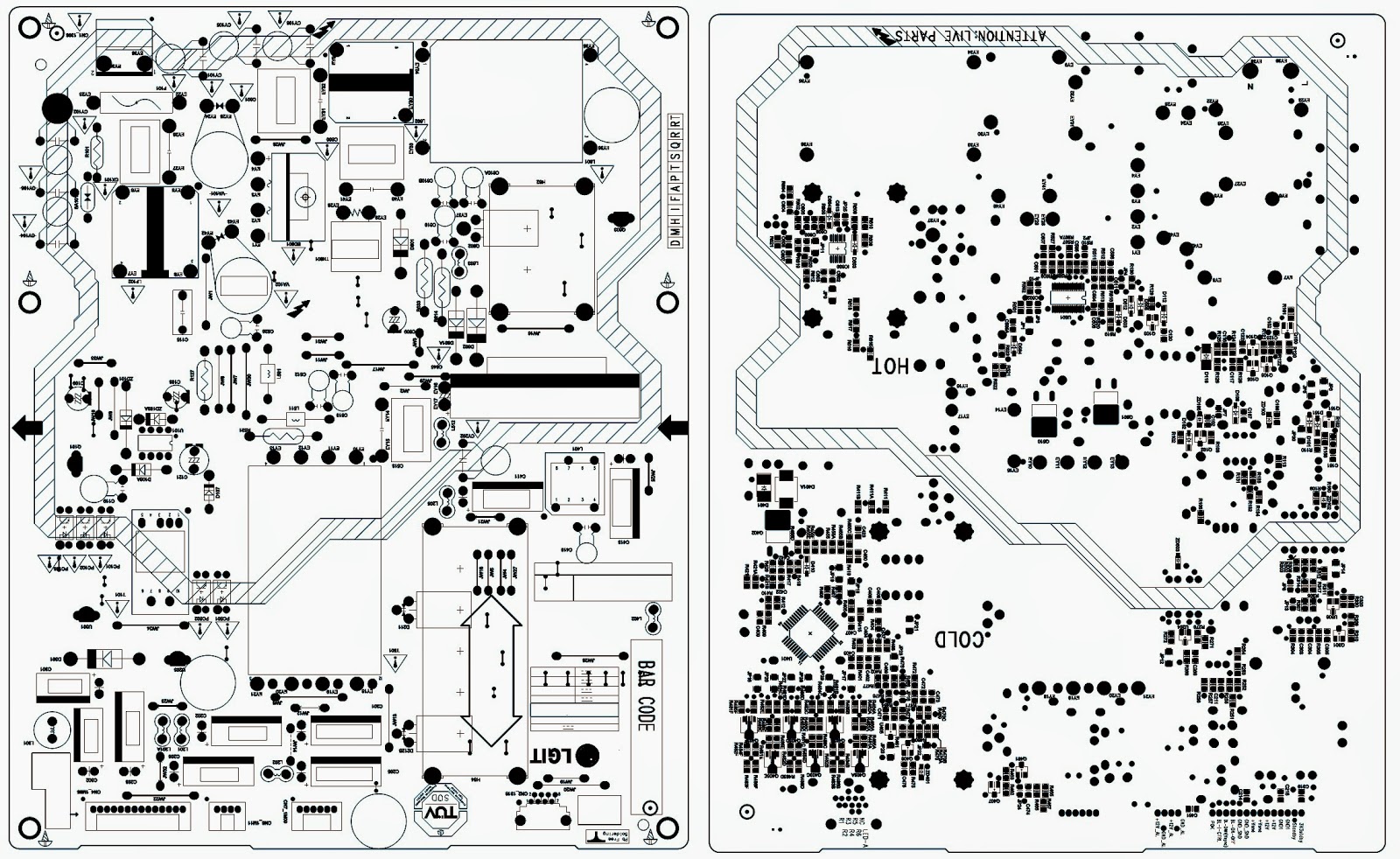
SSB [Small Sognal Board] Identification
SSB’s of this chassis are identified by a “715” code on the SSB. 715Axxxx-Nnn-MMM-OOOO
> 15 main category, Printed Wiring Board
> Axxxx sub category, sequential coding number
> Nnn Version code
> N Development number
> nn Production number
> MMM Mounting variation code
> OOOO Optional variation code
Make sure when replacing an SSB the SSB identification codes match the replacement panel.
Reset of Repaired SSB
A very important issue towards a repaired SSB from a Service repair shop (SSB repair on component level) implies the reset of the NVM on the SSB.
A repaired SSB in Service should get the service Set type “00PF0000000000” and Production code “00000000000000”.
Also the virgin bit is to be set. To set all this, you can use the ComPair tool or use the “NVM editor” and “Dealer options” items in SAM (do not forget to “store”).
After a repaired SSB has been mounted in the set (set repair on board level), the type number (CTN) and production code of the TV has to be set according to the type plate of the set. For this, you can use the NVM editor in SAM. The loading of the CTN and production code can also be done via compare (Model number programming).  In case of a display replacement, reset the “Operation hours display” to “0”, or to the operation hours of the replacement display.
Remark:
# After the NVM has been replaced, go to SAM and scroll to the <Reload MAC address>
# Select the item and press <OK> on the RC.
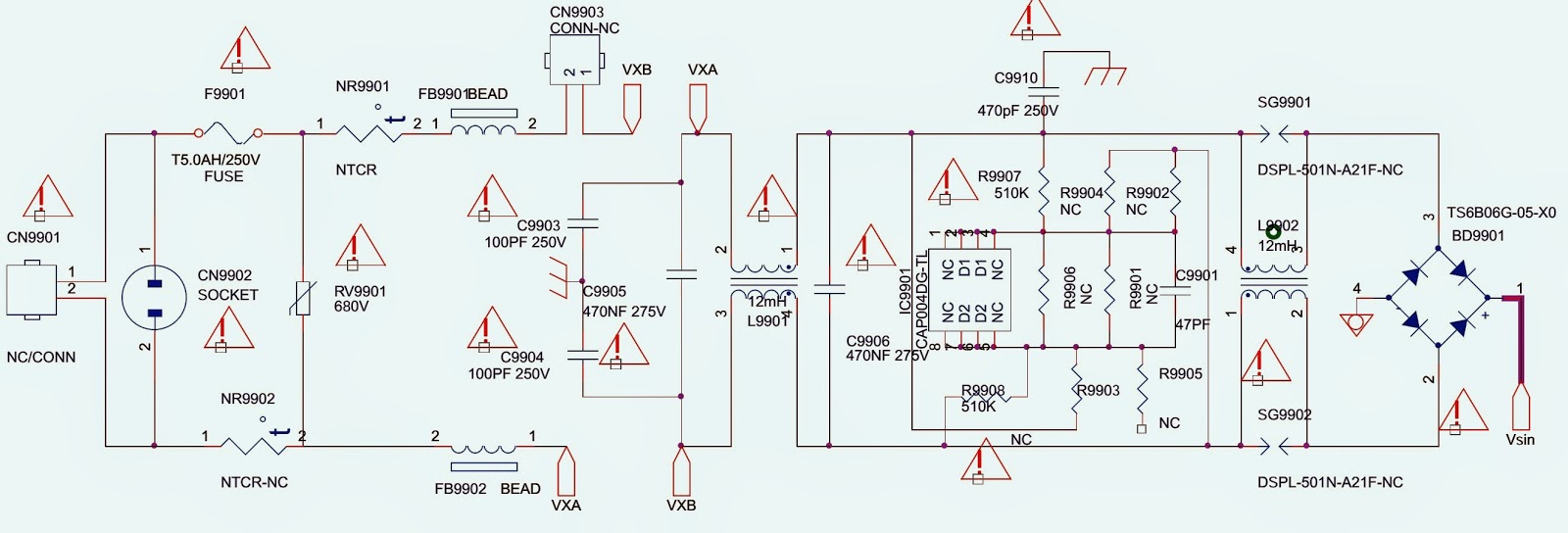
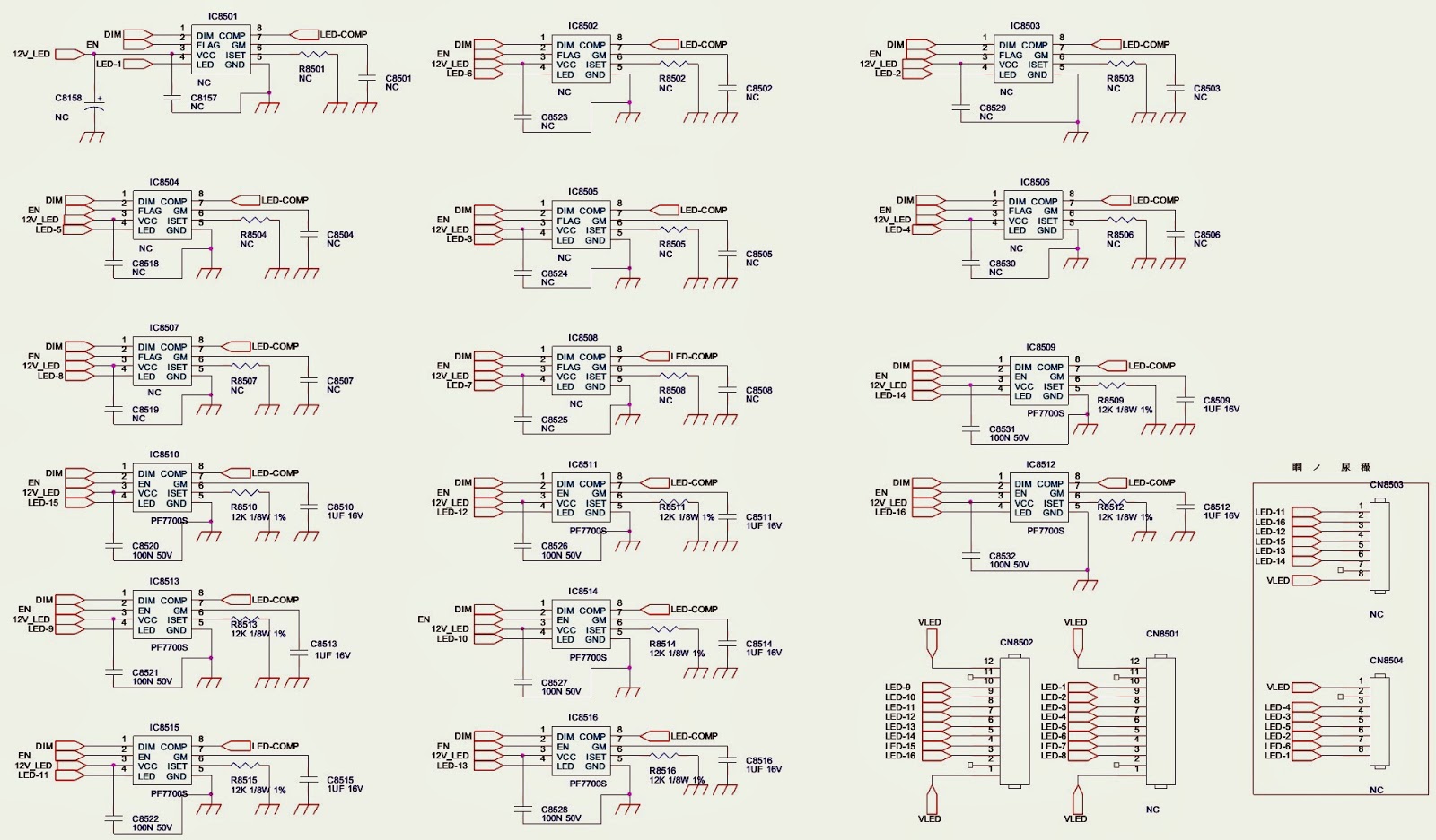
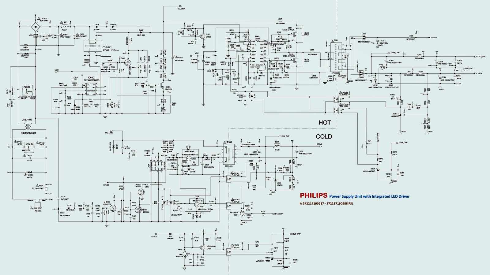
Power Supply Unit
All power supplies are a black box for Service. When defective, a new panel must be ordered and the defective one must be returned, unless the main fuse of the panel is broken. Always replace a defective fuse with one with the correct specifications.
Important delta’s with the TPS10.L LA classis platform are:
* New power architecture for LED backlight
* “Boost”-signal is now a PWM-signal + continuous variable.
The control signals are:
* Stand-by
* Inverter “on/off”
* DIM (PWM) (not for PSDL)
The output voltages to the chassis are:
* +4V7-STANDBY (Stand-by mode only)
* +12V (on-mode)
* +Vsnd (+24V) (audio power) (on-mode)
* +24V (bolt-on power) (on-mode)
* Output to the display; in case of
> IPB: High voltage to the LCD panel
> PSL and PSLS (LED-driver outputs)
> PSDL (high frequent) AC-current.
The diversity in power supply units is mainly determined by the diversity in displays.
The following displays can be distinguished:
* CCFL/EEFL backlight: power panel is conventional IPB
* LED back-light:
> side-view LED without scanning: PSL power panel
> side-view LED with scanning: PSLS power panel
> direct-view LED without 2D-dimming: PSL power panel
> direct-view LED with 2D-dimming: PSDL power panel.
PSLstands for Power Supply with integrated LED-drivers.
PSLSstands for a Power Supply with integrated LED-drivers with added Scanning functionality (added microcontroller).
PSDL stands for a Power Supply for Direct-view LED backlight with 2D-dimming.
Connector voltages
* +3V3-STANDBY, power supply for LED/IR receiver and controls
* +12V, input from the power supply for the panel common(active mode)
* +24V, input from the power supply for the AMP
* +1V2, from the power supply for the scaler IC MST6931
* +1V8, supply voltage for MST6931 DDR POWER
* +3V3, genenal supply voltage
* +3V3-TUN, supply voltage for tuner
* +5V nomal supply voltage for headphone AMP
* +5V-USB, input intermediate supply voltage for the USB Power
* +3V3 from the power supply for the scaler IC MST6931

PANASONIC TX-28MD4 - TX-25MD4 - TX-21MD4 - EURO-4 CHASSIS – SERVICE MODE – ADJUSTMENTS

$
0
0
How to enter Service Mode _ TV to memory pack process_Memory pack to TV process_Self check Procedure_ SMPS (Power Regulator section circuit diagram) _ Universal Remote control Set-up Codes to check with Panasonic Brand Televisions.
SERVICE MODE
* Set the Bass to maximum position, set the Treble to minimum position, press the F button followed by the volume down button on the customer controls at the front of the TV and at the same time press the "INDEX" button on the remote control, this will place the TV into the Service Mode.
* Press the RED / GREEN buttons to step up / down through the functions.
* Press the YELLOW / BLUE buttons to alter the function values.
* Press the STR button after each adjustment has been made to store the required values.
* To exit the Service Mode, press the "N" button.
[This TV also has the option of using a Memory Pack which enables you to copy the preset TV channels into the Memory Pack and then download them onto this or any other EURO-4 TV set.]
TV to Memory Pack process
1 Plug the memory pack into the AV1 21 pin terminal at the back of the TV and switch the TV on.
2 Go into Service Mode as explained above. The screen will show :  Program External>>TV.
3 Press the BLUE button on the remote control.  The screen will show : Program TV>>External.
4 Press the STR button on the TV.  The screen will show : Please Wait.
5 All the tuning information stored inside the TV will now be transferred to the Memory Pack. This process will take 2-3 minutes to complete and when finished the screen will show : Complete.
Memory Pack to TV process
* Plug the memory pack into the AV1 21 pin terminal at the back of the TV and switch the TV on.
* Go into Service Mode as explained above.  The screen will show : Program External>>TV.
* Press the STR button on the TV. The screen will show : Please Wait
All the tuning information stored inside the Memory Pack will now be transferred to the TV. This process will take 2-3 minutes to complete and when finished the screen will show : Complete.
The tuning information from the Memory Pack has now been copied into the TV.
* To exit from the Service Mode press the "N" button.
*  The process has now been completed and the Memory Pack can now be removed.
If an error occurs while using the Memory Pack the TV will detect this and the screen will show : Error;  
  {If this happens then press the "N" button and repeat the process that was being used. If the errors continue to occur then check the connectors between the TV and the memory pack and check the 9V battery inside the memory pack.}
SELF CHECK
Self-check is used to automatically check the bus lines and hexadecimal code of the TV set. To get into the Self-Check mode press the down (-/v) button on the customer controls at the front of the set, at the same time pressing the STATUS button on the remote control, and the screen will show:
[If the CCU ports have been checked and found to be incorrect or not located then " - - " will appear in place of "O.K.".]
ADJUSTMENT PROCEDURE
Additional information for Self-Check feature
(Information in brackets {} refers to the TX-21MD4)
FACTORY SETTINGS
  To return customer settings to factory settings and clear owner ID of all information input by the customer, enter Self-Check mode. Press the down (-/v) button on the customer controls at the front of the TV set, at the same time pressing the STATUS button on the remote control. To exit Self Check, switch off the TV set at the power button.
  Self Check is also used to automatically check the bus lines and hexadecimal code of the TV set. If the CCU ports have been checked and found to be incorrect or not located then " - - " will appear in place of "O.K.". For more in-depth TV diagnostics use the LUCI interface as listed below.
Service Aids
To aid in the service of our current chassis there are a number of Service Aids which have been made available.
LUCI interface kit (Linked Utility Computer Interface) Part number: TZS6EZ002.
This contains interface and cables for connecting TV service connector and a PC as well as diagnostic software. As new models are introduced upgrade software will become available.
VICI (Visual Interactive Computer Information):  These C.D.’s contain multimedia documentation providing quick access to service information. Part No. TZS7EZ006 & TZS7EZ005
TASMIN (Technically Advanced System for Multimedia Interactive Notes).  As well as providing a first step towards more interactive training this product also achieves quick access to Technical Information.
NOTE: Self Check should only be used when refurbishing the TV set and not during normal repair work.
SMPS SCHEMATIC
CLICK ON THE PICTURES TO MAGNIFY
Universal Remote Control Set-up codes to check with Panasonic Brand Televisions.[CRT, LCD & Plasma types]
0016 0032 0033 0049 0054 0075 0099 0101 0104 0107 0110 0119 0143 0151 0152 0161 0166 0207 0249 0304 0305 0306 0396 0420 0461 0611 0631 0633 0692

SMPS POWER SUPPLY - 40LP32S-PWH1XG – SCHEMATIC (Circuit Diagram)

$
0
0
Used ICs _ - L6562D_FSQ510_SG3525
BACK-LIGHT INVERTER
CLICK ON THE SCHEMATICS TO ZOOM IN

TCL POWER SUPPLY [SMPS] – 40E371C4P-WA1XG – SCHEMATIC

$
0
0
Used ICs_ Viper17l _ FAN7930C _ KA12A50D[FET] _FSFR1700XS_ TCP781&TLP781(Opto-couplers)
CLICK ON THE SCHEMATICS TO MAGNIFY

SANYO FVM4612 - DP46132 - DP46132M - DIS-ASSEMBLY - POWER SUPPLY [SMPS] SCHEMATIC

$
0
0
SANYO FVM4612 - DP46132 - DP46132M _ Power Board _ 715G5246P01W22002H _ Disassemble Procedure.
DISASSEMBLE PROCEDURE
* Remove the screws to remove the stand.
* Remove the screws to remove the rear cover.
* Unplug these connectors and cable clip on the IR boardKey boardmain board and power board.
* Remove the screws to remove the IR BoardKey BoardMain BoardPower Board and Deco Bezel.
* Remove the speakers
* Remove the screws to remove the BKT and cover hinge.
* Unplug the LVDS.
* Remove the panel.
POWER SUPPLY BOARD [SMPS] SCHEMATIC (Circuit Diagram)
CLICK ON THE PICTURES TO MAGNIFY


VESTEL 17PW07 – POWER SUPPLY – SMPS – SCHEMATIC - Circuit diagram

$
0
0
LC32LE511 – LC40LE511 – LC40LE531VESTEL 17PW07- POWER SUPPLY [SMPS] SCHEMATIC _Circuit Diagram (32” & 42” SLIM LED TV)
CLICK ON THE SCHEMATIC TO MAGNIFY

PHILIPS 37PFL5422/96 – PHILIPS 42PFL5422/96 – SMPS (POWER SUPPLY) - SCHEMATIC

$
0
0
PHILIPS 37PFL5422/96– PHILIPS 42PFL5422/96– SMPS (POWER SUPPLY) – SCHEMATIC [Circuit Diagram]
37PFL5422/96 SMPS SCHEMATIC
42PFL5422/96 SMPS SCHEMATIC
CLICK ON THE SCHEMATICS TO MAGNIFY

FUNAI CTV S2900PF - SCHEMATIC (Circuit Diagram)

$
0
0
STR-G9656 – TMP8827PSNG – ATM24C08 – TA8246 – TC90L01NFUNAI S-2900PF -  Color TV CIRCUIT DIAGRAM
SCHEMATIC [Circuit Diagram]
SMPS SECTION
CLICK ON THE SCHEMATICS TO ZOOM IN

LED LCD TV - PHILIPS - 32" and 42" 5000 series Power Supply - SMPS SCHEMATIC

$
0
0
PHILIPS Power Supply Unit with Integrated LED Driver - A 272217190587 - 272217190588 PSL [ 32" 5000 series & 42" 5000 series] LED LCD TV
SCHEMATIC
PWB
CLICK ON THE SCHEMATICS TO MAGNIFY
32" 5000 series & 42" 5000 series - POWER SUPPLY BOARDS

PHILIPS 32PFL3506/F7 - 32PFL3000/F8 - SERVICE MODE - SOFTWARE UPGRADE

$
0
0
How to enter Service Mode _ Initialization _  Firmware Upgrade _ White Balance adjustment _ PHILIPS 32PFL3506/F7 - 32PFL3000/F8 _ LCD TV
SERVICE MODE
* Turn the power on.
* Press [MENU] button to display Setup menu.
* Select “Features”.
* Select “Current Software Info”.
* Press [0], [6], [2], [5], [9], [6] and [INFO] buttons on the remote control unit in this order. The following screen appears.
Purity Check
This mode cycles through full-screen displays of red, green, blue, and white to check for non-active pixels.
* Enter the Service mode.
* Each time the [7] button on the remote control unit is pressed, the display changes as follows.
* To cancel or to exit from the Purity Check Mode, press [PREV CH] button.
VCOM Adjustment
Set the color analyzer at the zero point calibration and bring the optical receptor pointing at the center of the LCD-Panel at a distance of 1.18 inches(3cm) away from the LCD-Panel surface.
Note: The optical receptor must be set perpendicularly to the LCD Panel surface.
* Enter the Service mode.
* Press [2] button on the remote control unit.
* Press [CH + or -] buttons on the remote control unit so that the color analyzer value becomes minimum within 2 minutes from Power-On.
* To cancel or to exit from the VCOM Adjustment, press [PREV CH] button.
The White Balance Adjustment should be performed when replacing the LCD Panel or Digital Main CBA
Symptom of Maladjustment: White becomes bluish or reddish.
Operate the unit for more than 60 minutes.
Input the White Raster(70%=70IRE, 40%=40IRE).
> Set the color analyzer at the CHROMA mode and zero point calibration. Bring the optical receptor pointing at the center of the LCD-Panel at a distance of 1.18 inches (3cm) away from the LCD Panel surface.
Note: The optical receptor must be set perpendicularly to the LCD Panel surface.
Enter the Service mode. Press [VOL -] button on the remote control unit and select “C/D” mode.
CUTOFF
> Press [1] button to select “COR” for Red Cutoff adjustment. Press [3] button to select “COB” for Blue Cutoff adjustment.
DRIVE
> Press [4] button to select “DR” for Red Drive adjustment. Press [6] button to select “DB” for Blue Drive adjustment.  In each color mode, press [CH + or -] buttons to adjust the values of color.
> Adjust Cutoff and Drive so that the color temperature becomes 12000°K (x= 0.272 / y= 0.278 ± 0.005).
To cancel or to exit from the White Balance Adjustment, press [PREV CH] button.
HOW TO INITIALIZE THE LCD TV
The purpose of initialization is to place the set in a new out of box condition. The customer will be prompted to select a language and program channels after the set has been initialized.  To put the program back at the factory-default, initialize the LCD TV using the following procedure.
32PFL3506/F7 - 32PFL3000/F8 -  (Serial No.: DS1, XA1) - (Serial No.: XA1)
* Turn the power on.
* Enter the service mode.   To cancel the service mode, press [Power] button on the remote control unit.
* Press [INFO] button on the remote control unit to initialize the LCD television. "INITIALIZED" will appear in the upper right of the screen. "INITIALIZED" color will change to green from red when initializing is completed.
32PFL3506/F7 - 32PFL3000/F8 (Serial No: DS2, DS3) - (Serial No: XA2)
* Turn the power on.
* Enter the service mode.   To cancel the service mode, press [Power] button on the remote control unit.
* Press [FREEZE] button on the remote control unit to initialize the LCD television.
"INITIALIZED" will appear in the upper right of the screen. "INITIALIZED" color will change to green from red when initializing is completed.
Firmware Update Procedure
Note: There are two states (the User Upgrade and the Factory Upgrade) in firmware update.
User Upgrade> Upgrade the firmware only.  The setting values are not initialized.
Factory upgrade> Upgrade the firmware and initialize the setting values.
Factory Upgrade (Flash upgrade)> Upgrade the firmware and initialize the setting values along with the setting data adjusted at the factory such as White Balance, etc.
32PFL3506/F7 (Serial No.: DS2, DS3) _ 32PFL3000/F8 (Serial No.: XA2)
The identification of User Upgrade and Factory Upgrade are done by the filename.
* Turn the power off and unplug the AC Cord.
* Insert the USB storage device to the USB port as shown here.
* The update will start and the following will appear on the screen.
* When the firmware update is completed, the following will appear on the screen.
* Remove the USB storage device from the USB port.
* Turn the power off and turn the power on again.
When the Factory Upgrade is used, after restarting TV, shift to initial screen menu in service mode. "INITIALIZED" will appear on the upper right of the screen. "INITIALIZED" color will
change to green from red when initializing is completed.

Viewing all 2033 articles
Browse latest View live


<script src="https://jsc.adskeeper.com/r/s/rssing.com.1596347.js" async> </script>