Quantcast
Channel: Electro help
Viewing all 2033 articles
Browse latest View live

TOSHIBA LC-1945W – LC-2245W - LC 4245 - KONKA LIPS22 POWER and BACK-LIGHT INVERTER SCHEMATIC

$
0
0
Toshiba LC1945W_LC2245W_LC4245W and KONKA LIPS22 _  Power and Back-light inverter Schematic.
SEMP Toshiba LC1945W_LC2245W_LC2645_LC3245W_LC4345W
KONKA LIPS22 & TOSHIBA LC1945W_LC2245W_POWER & BACK-LIGHT INVERTER Circuit Diagram.  {Click on the Schematics to Zoom In}
Power [Toshiba & konka 19" LCD TV]
B-L Inverter [Toshiba & Konka]
TOSHIBA LC 3245W POWER - Toshiba _ 300W
TOSHIBA LC 4245W POWER - 300W


JBL BALBOA SERIES Powered SUB-10 – CIRCUIT DIAGRAM – (Schematic) - Troubleshooting

$
0
0
JBL SUB-10 _ POWERED SUB-WOOFER _ SCHEMATIC _ [Circuit Diagram] _ Troubleshooting flow chart
Specifications
Amplifier Power (RMS): 100 Watts
Peak Dynamic Power : 225 Watts
Driver: 10" (254mm)
Inputs: Line Level and LFE
Crossover Frequency: Variable from 50Hz to 150Hz, 24 dB per octave
Frequency Response: 30Hz – 150Hz
Dimensions (H x W x D):
19-3/4" x 14-1/16" x 14-3/4" (502mm x 357mm x 375mm)
Weight: 35 lb/16kg
General Unit Function (UUT = Unit Under Test)
* Switches/knobs on the amplifier face-plate:
* Low Pass Frequency Adjust full CW (150Hz)
* Phase switch – either position
* From the signal generator, Connect both right and left line level inputs (RCA) – not the LFE jack - to signal generator and UUT. Use Y-cable if necessary from mono source.
* On the amplifier, turn the LEVEL control full Counterclockwise (Min).
Turn on generator, adjust to 100mV, 50 Hz.
* Plug in UUT; turn the power switch ON. Turn LEVEL control full Clockwise (Max).
LED should now be Green; immediate bass response should be heard and felt from rear port tube opening.  Turn off generator, turn LEVEL control fully Counterclockwise (Min), disconnect RCA cable.
Sweep Function
Follow steps above, using a sweep generator as a signal source.
Sweep generator from 20Hz to 1kHz. Listen to the cabinet and drivers for any rattles, clicks, buzzes or any other noises. If any unusual noises are heard, remove woofer and test.
Driver Function (Woofer)
* Remove woofer from cabinet; detach + and - wire clips.
* Check DC resistance of woofer; it should be 3.3 ohms ±10%.
* Connect a pair of speaker cables to driver terminals. Cables should be connected to an integrated amplifier fed by a signal generator. Turn on generator and adjust so that speaker level output is 5.0V.
Sweep generator from 20Hz to 1kHz. Listen to driver for any rubbing, buzzing, or other unusual noises.
Adjust Level
Turn your Sub-woofer-Level Controlup to the “5” position (halfway). If no sound emanates from the sub-woofer, check the AC-line cord and input cables. Are the connectors on the cables making proper contact? 

Is the AC plug connected to a “live” receptacle? 
Has the Power Switch  been pressed to the “On” position? 
Once you have confirmed that the sub-woofer is active, proceed by playing a CD, record or cassette. Use a selection that has ample bass information.
Set the overall volume control of the pre-amplifier or stereo to a comfortable level. Adjust the Sub-woofer-Level Control  until you obtain a pleasing blend of bass. Bass response should not overpower the room but rather be adjusted so there is a harmonious blend across the entire musical range. Many users have a tendency to set the sub-woofer volume too loud, adhering to the belief that a sub-woofer is there to produce lots of bass. This is not entirely true.  A sub-woofer is there to enhance bass, extending the response of the entire system so the bass can be felt as well as heard. However, overall balance must be maintained or the music will not sound natural. An experienced listener will set the volume of the sub-woofer so its impact on bass response is always there but never obtrusive.
Phase Control
The Phase Switchdetermines whether the sub-woofer speaker’s piston-like action moves in and out with the main speakers (0˚), or opposite the main speakers (180˚). Proper phase adjustment depends on several variables such as room size, sub-woofer placement and listener position. 

Adjust the phase switch to maximize bass output at the listening position.  Crossover Adjustments  The Crossover Adjustment Control  determines the highest frequency at which the sub-woofer reproduces sounds. If your main speakers can comfortably reproduce some low-frequency sounds, set this control to a lower frequency setting, between 50Hz and 100Hz. This will concentrate the sub-woofer’s efforts on the ultra deep bass sounds required by today’s films and music. If you are using smaller bookshelf speakers that do not extend to the lower bass frequencies, set the Crossover Adjustment Control to a higher setting, between 120Hz and 150Hz.
NOTE: This control will have no effect if the LFE Input ¢
is used. If you have a Dolby Digital or DTS processor/receiver, the Low-Pass Frequency is set by the processor/receiver. Consult your owner’s manual to learn how to view or change this setting.
EXPLODED VIEW
SCHEMATICS
Troubleshooting
CLICK ON THE PICTURES TO MAGNIFY

SONY KV-SW29M50 – KV-SW29N60 Trinitron CTV – HOW TO ENTER SERVICE MODE

$
0
0
HOW TO ENTER SERVICE MODE _ SONY KV-SW29M50 – KV-SW29N60 Trinitron CTV_ LED blinking codes _ Universal Remote Control Set-up codes to check with Sony TVs (For CRT, LCD & Plasma TVs) _ Power Supply & Deflection Circuit Diagram _ RGB Amp / Rotation & Landing Correction Circuit.

APPLICABLE TO:
KV-SW29M50 _ RM-W104 E SCC-V21B-A
KV-SW29M50 _ RM-W104 Malaysia SCC-U96V-A
KV-SW29M61 _ RM-W103 GE SCC-V04Q-A
KV-SW29M61 _ RM-W103 Malaysia SCC-U96U-A
KV-SW29M80 _ RM-W104 E SCC-V21A-A
KV-SW29M80 _ RM-W104 Middle East SCC-V18G-A
KV-SW29M81 _ RM-W103 Middle EastSCC-V18H-A
KV-SW29N60 _ RM-W150 Philippines SCC-U87T-A
KV-SW29M80 _ RM-W104 Saudi Arabia SCC-V10W-A
TO ENTER SERVICE MODE
Press the remote control buttons in sequence: [DISPLAY] >  5 >  [VOL + ] > [POWER].  This operation sequence puts the unit into service mode.  This screen display:
METHOD OF CANCELLATION FROM SERVICE MODE
Set the standby condition (Press [POWER] button on the commander), then press [POWER] button again, here upon it becomes TV mode.
METHOD OF WRITE INTO MEMORY
* Set to Service Mode.
* Press 1 (UP) and 4 (DOWN), to select the adjustment item.
* Change item by pressing 3, 6.
* Press [MUTING] button to indicate WRITE on the screen.
* Press [0] button to write into memory.
MEMORY WRITE CONFIRMATION METHOD
After adjustment, pull out the plug from AC outlet, and then plug into AC outlet again.
Turn the power switch ON and set to Service Mode.
Call the adjusted items again to confirm adjustments were made.
OTHER FUNCTION VIA REMOTE COMMANDER
* 7,0 All the data becomes the values in memory.
* 8, 0 All user control goes to the standard state.
* [Display], 0 Service data initialization (Be sure not to use usually.)
* 2, 5 Select Device or Category (Up, Down)
ADJUSTMENT METHOD
Item Number 000HPOS
This explanation uses H POSITION as an example.
1 Select "000 HPOS" with the 1 and 4 buttons, or 2 and 5.
2 Raise/lower the data with the 3 and 6 buttons.
3 Select the optimum state. (The standard is IF for PAL reception.)
4 Write with the [MUTING] button. (The display changes to WRITE.)
5 Execute the writing with the - button. (The WRITE display will be changed to red color while executing, and back to SERVICE.)
Use the same method for all Items. Use 1 and 4 to select the adjustment item, use 3 and 6 to adjust, write with [MUTING], and then execute the write with [0].
Note: In [WRITE], the data for all items are written into memory together.
For adjustment items that have different standard data between 50Hz or 60Hz, be sure to use the respective input signal after adjustment.
SELF DIAGNOSTIC FUNCTION (LED Blinking Codes)
When an error occurs, the STANDBY indicator will flash a set number of times to indicate the possible cause of the problem. If there is more than one error, the indicator will identify the first of the problem areas.
Result for all of the following diagnosis items are displayed on screen. No error has occurred if the screen displays a "0".
Note: If a + B over current is detected, stoppage of the vertical deflection is detected simultaneously.  The symptom that is diagnosed first by the micro-controller is displayed on the screen.
Universal Remote Control Set-up Codes.
0018 0045 0101 0131 0154 0177 0211 0301 0302 0357 0358 0609 0785
POWER SUPPLY & DEFLECTION CIRCUIT
RGB AMP / ROTATION / LANDING CORRECTION CIRCUIT
CLICK ON THE PICTURES TO MAGNIFY

HOW TO ENTER SERVICE MODE TO SHARP SE32JW73E01 32 Inch COLOR TV

$
0
0
SHARP  SE32JW73E01 PAL B/G, I / SECAM L/Lí, B/G, D/KSYSTEM COLOUR TELEVISION _ Service Mode _ Adjustment Details.
SERVICE MODE
All adjustments to this chassis, except for focus, are carried out in the Service Mode.  The Service Mode is provided to enable the engineer to correctly set up the receiver to the CRT fitted in the set.  Note that these adjustments may vary from one receiver to another.
To enter the Service Mode, carry out the following procedure.
1 Connect a test pattern to the antenna terminal.
2 Tune the receiver to this signal.
3 Turn the receiver off using the mains switch.
4 Press volume down and channel up buttons on the front of the receiver at the same time.
5 Keeping these buttons pressed, turn the mains on.
6 When the set starts up it will be in Service Mode.
7 Release the two buttons.
> Use the channel up and down buttons to move between the options.
> Use the volume control buttons to change the data.
> To store the data, use the stand-by button on the remote control.
>
To exit the Service Mode, turn the receiver off using the mains switch.
When the Service Mode is entered the On Screen Display appears.
The figures displayed in the XXXX locations are hexadecimal representations of the number of times that particular function has been executed. For example if the hexadecimal number displayed after SW on was 0E4A, this would correspond to the receiver being turned on 3658 times. The figure displayed in the **_**x** location is the EPROM version.
Adjustment menu
01. Horizontal Shift
02. East West Width
03. Pin Phase
04. Pin Amp (Amplitude)
05. Corner Amplitude
06. Corner Symmetry
07. Vertical Linearity
08. Vertical Angle
09. Vertical Bow
10. Vertical Amplitude
11. S Correction
12. Vertical Shift
13. Red Gain
14. Green Gain
15. Blue Gain
16. Red Cut Off
17. Green Cut Off
18. Blue Cut Off
19. Alter NVM Pag (Page)
20. Alter NVM Pos (Position)
21. Alter NVM Val (Value)
22. Teletext Mix Mode Contrast
23. Teletext Contrast
24. OSD Contrast
25. DVCO Adjustment (Only PAL)
26. DVCO Adjustment (Only NTSC)
27. AGC Adjustment (B/G or L depen-
ding on the receiving signal)
28. Auto Installation On/Off
 When in the Service Mode it is possible to access certain functions by using the teletext keys as below
By pressing the Blue button each adjustment can be directly accessed via the remote control. Referring to the list above, press the Blue button followed by the adjustment number, this will directly access the selected adjustment. 
If any number above 29 is selected, the set will revert to the Service Mode entry page. To access a number less than 10, use the 0 key first, i.e. 02.
* Press the Yellow button to go straight to the AGC adjustment.
* Press the Green button once to enter FACTORY VOLUME level. Use volume control keys to change the setting. The original value will be recovered after resetting the TV set.
* Press the Green button twice to enter FACTORY BALANCE level. Use volume control keys to change the setting. The original value will be recovered after resetting the TV set.
* Press the Green button three times to enter FACTORY BASS level. Use volume control keys to change the setting. The original value will be recovered after resetting the TV set.
* Press the Green button four times to enter FACTORY TREBLE level. Use volume control keys to change the setting. The original value will be recovered after resetting the TV set.
* Press the Red button once to enter FACTORY CONTRAST level. Use volume control keys to change the setting. The adjustment is stored automatically.
* Press the Red button twice to enter FACTORY BRIGHTNESS level. Use volume control keys to change the setting. The adjustment is stored automatically.
* Press the Red button three times to enter factory COLOR level. Use volume control keys to change the setting. The adjustment is stored automatically.  If buttons 0 through 9 are pressed, the set will automatically go to that program number.
* By pressing the Menu button, the unit will normalize Picture and Audio settings. The Auto Installation is then turned on.
Note that the receiver should be set to FULL MODE before carrying out any geometry adjustments. This can be achieved by pressing the widescreen mode button on the remote control until FULL MODE appears on the OSD. This can only be done out of the Service Mode.
Horizontal
Horizontal Shift
E-W Width
Pin Phase
Pin Amp
Corner Amplitude
Corner Symmetry
Just in case the TV set requires a full geometry adjustment, please proceed first with Vertical according to the above order, and after that, adjust Horizontal according to the above order.
Horizontal Shift
Adjust the Horizontal Shift so that the picture is centered.
> When the volume up button is pressed, the picture moves to the right.
> When the volume down button is pressed, the picture moves to the left.
> Press the stand-by button on the remote control to store.
E-W Width
Adjust the E-W Width so that 8% over-scan is achieved.
> When the volume up button is pressed, horizontal scanning decreases.
> When the volume down button is pressed, horizontal scanning increases.
> Press the stand-by button on the remote control to store.
Pin Phase
Adjust the Pin Phase so that the picture is symmetrical top and bottom.
> When the volume up button is pressed, side pincushion changes.
> When the volume down button is pressed, side pincushion changes.
> Press the stand-by button on the remote control to store.
Pin Amp
Adjust the Pin Amp so that the picture is centered.
> When the volume up button is pressed, side pincushion changes from pincushion to barrel shape.
> When the volume down button is pressed, side pincushion changes from barrel shape to pincushion.
> Press the stand-by button on the remote control to store.
Corner Amplitude
Adjust the Corner Amplitude so that the picture is centered.  Note: This adjustment affects to upper and lower sides.
> When the volume up button is pressed, side pincushion changes from pincushion to barrel shape.
> When the volume down button is pressed, side pincushion changes from barrel shape to pincushion.
> Press the stand-by button on the remote control to store.
Corner Symmetry
Adjust the Corner Symmetry so that the picture is centered.
Note: This adjustment affects to upper and lower sides.
> When the volume up button is pressed, side pincushion changes from barrel shape to pincushion.
> When the volume down button is pressed, side pincushion changes from pincushion to barrel shape.
> Press the stand-by button on the remote control to store.
CLICK ON THE PICTURE TO ZOOM IN
Vertical
Vertical Amplitude
Vertical Shift
Vertical Bow
Vertical Angle
S Correction
Vertical Linearity
Vertical Linearity
Adjust the Vertical Linearity so that the upper and lower parts of the picture are symmetrical.
> When the volume up button is pressed, the upper picture scanning decreases and the lower picture scanning increases.
> When the volume down button is pressed, the upper picture scanning increases and the lower picture scanning decreases.
> Press the stand-by button on the remote control to store.
Vertical Angle
Adjust the Vertical Angle so that the picture is centered.
> When the volume up button is pressed, the vertical angle changes to right.
> When the volume down button is pressed, the vertical angle changes to left.
> Press the stand-by button on the remote control to store.
Vertical Bow
Adjust the Vertical Bow so that the picture is centered.
> When the volume up button is pressed, the vertical bow changes to right.
> When the volume down button is pressed, the vertical bow changes to left.
> Press the stand-by button on the remote control to store.
Vertical Amplitude
Adjust the Vertical Amplitude so that 8% over-scan is achieved.
> When the volume up button is pressed, the vertical size of the picture increases.
> When the volume down button is pressed, the vertical size of the picture decreases.
> Press the stand-by button on the remote control to store.
S - Correction
Adjust the S Correction so that the picture symmetrical between the top, center and bottom.
> When the volume up button is pressed, the top and bottom scanning increases and the center scanning decreases.
> When the volume down button is pressed the top and bottom scanning decreases and the center scanning increases.
> Press the stand-by button on the remote control to store.
Vertical Shift
Adjust the Vertical Shift so that the picture is centered.
> When the volume up button is pressed, the picture moves down.
> When the volume down button is pressed, the picture moves up.
> Press the stand-by button on the remote control to store.

ROTEL RA-840BX – INTEGRATED STEREO AMPLIFIER – CIRCUIT DIAGRAM _ Wiring Diagram

$
0
0
 CIRCUIT DIAGRAM (Schematic) & Wiring Diagram - ROTEL RA-840BX– (INTEGRATED STEREO AMPLIFIER)
WIRING DIAGRAM
CIRCUIT DIAGRAM (Schematic)
CLICK ON THE PICTURES TO MAGNIFY

CAIXA CONNECT 800 – WIRELESS SYSTEM - SCHEMATIC

$
0
0
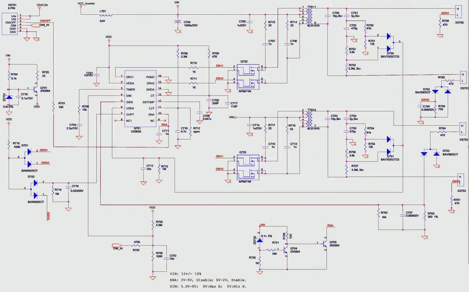
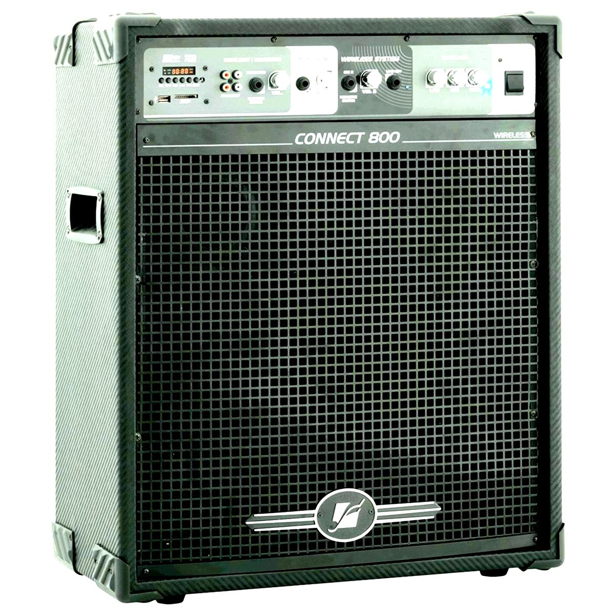
CONNECT 800WIRELESS SYSTEM - Circuit Diagram
SCHEMATIC {Click on the Schematic to Zoom In}


harman-kardon - BDP 20/230 - BDP 2/120 - Blu-ray player - Power Supply (SMPS) _ Schematic

$
0
0
SMPS Circuit Diagram _ BDP 20/230 - BDP 2/120 - Blu-ray player - harman/kardon
SMPS SCHEMATIC
PWB
CLICK ON THE PICTURES TO MAGNIFY


PHILIPS 29PT6807 – Slim TV - SMPS – VERTICAL OUT – HORIZONTAL OUTPUT – VIDEO OUTPUT – SCHEMATIC

$
0
0
29PT6807 Philips – Slim TV -  SMPS – VERTICAL OUT – HORIZONTAL OUTPUT – VIDEO OUTPUT – SCHEMATIC (Circuit Diagram) 
Used ICs _ STR-W6556A_TDA4863AJ_TFA9843AJ(10W)_TFA9842AJ(6W)
SMPS [Power supply regulator] SCHEMATIC
VIDEO OUTPUT [CRT BASE CARD]
LINE DEFLECTION [HORIZONTAL SCAN OUTPUT]
FRAME DEFLECTION [VERTICAL SCAN OUTPUT]
AUDIO [SOUND] OUTPUT
CLICK ON THE SCHEMATICS TO MAGNIFY


PANASONIC TH-L32X10A LCD TV - HOW TO ENTER SERVICE MODE - SMPS SCHEMATIC

$
0
0
Power Supply Regulator Board Circuit Diagram _ Service Mode _ Universal Remote Control Set-up Codes_Panasonic TH-L32X10A LCD TV-LCD TV
SERVICE MODE
* While pressing [-/v] button of the main unit, press [INFO] button of the remote control three times within 3 seconds.
Key command
> “1” button...Main items Selection in forward direction
> “2” button...Main items Selection in reverse direction
> “3” button...Sub items Selection in forward direction
> “4” button...Sub items Selection in reverse direction
> “VOL” button...Value of sub items change in forward direction ( + ), in reverse direction ( - )
TO EXIT Service Mode - Switch off the power with the [POWER] button on the main unit or the [POWER] button on the remote control.
SMPS_BACK-LIGHT
Click on the pictures to Zoom In
Universal Remote Control set-up codes to check with Panasonic Brand TVs (CRT, LCD & Plasma models)
0016 0032 0033 0049 0054 0075 0099 0101 0104 0107 0110 0119 0143 0151 0152 0161 0166 0207 0249 0304 0305 0306 0396 0420 0461 0611 0631 0633 0692

BDT 30/230 - BDT 3/120 Blu-ray player - harman/kardon - SMPS Circuit diagram

$
0
0
harman/kardon - BDT 30/230 - BDT 3/120 Blu-ray player– SMPS schematic – General troubleshooting – Firmware update Procedure.
SPECIFICATIONS
> Supported disc formats: 5-inch (12cm) or 3-inch (8cm) Bd-video (single-layer or double-layer), Bd-R, Bd-Re, DVD-video, DVD+R/+RW, dvd-R/-RW, CDDA (CD digital audio), CD-R/RW discs
> Region code (BD/DVD): A/1 (BDT 3); B/2 (BDT 30)
> Audio formats: DOLBY digital, DOLBY digital Plus, DOLBY Truehd, dTs digital, DTS-HD high Resolution
> Audio, DTS-HD Master Audio, PCM, CBR @192kbps, vBR @ 355kbps, MP3: 32kbps – 320kbps bitrates, including variable bit rate encoding still-image format: JPEG video signal system: NTSC (BDT 3); PAl (BDT 30)
> HDMI version: 1.4a with 3-d and 30/36-bit deep color
> Power requirement: Ac 110 – 240v, 50/60hz
> Power consumption: 25W maximum, <0.5W standby
> Dimensions (h x W x d): 2-5/8" x 17-5/16" x 13-7/8" (66mm x 440mm x 352mm)
> Weight: 8.2 lb (3.7kg).
* 06-RC2410-A001 REMOTE CONTROL
* 08-0BDT30-PWY ASSY-POWER BOARD
* 43-FS512S-216 DC FAN 5012F 320MM
Preparation to upgrade software
1 Power on the set and press “settings” button on the remote.
2 Press left cursor to select "Information". Check the Software Version.
3 Check that the software version is correct in the UPG folder.  For example: if the software version is displayed as “BDT20 XX.XX.XX”, the correct software is “BDT20_BD.bin”. Otherwise, the software is “BDT2_BD.bin”.
4 Start the CD Burning software and create a new CD project (Data Disc). Copy the UPG folder to the root directory of the data disc.
5 Burn the data onto a blank CDR.
Upgrade software via CDR
1 Power on the set and insert the prepared Upgrade CDR.
2 The set will start reading the disc .
3 When the BDT recognizes the disc, press Setting > System > System >  Upgrade > Disc. Follow the instructions on the screen.
4 About 3 minutes later, the BDT will automatically turn off, when upgrade has been completed.
Upgrade software via USB Flash Drive
1 Decompress the packed file, copy the UP G folder to the root directory of a USB memory device.
2 Insert the USB. The player will recognize the USB device automatically.
3 Press Setting > System > System Upgrade > Disc. Follow the instructions on the screen.
4 About 3 minutes later, the BDT will automatically turn off, when upgrade has been completed.
Read out the software version to confirm upgrade
1 Power on the BDT and press the “Settings” button on the remote.
2 Press left cursor on remote control to select "Information". The software version and other information will be displayed on the TV screen as follows:
Software Version: BDTX XX.XX.XX
Mac Address:XX-XX-XX-XX-XX-XX

Caution:The set must not be powered off during upgrading. Otherwise the Main board will be damaged entirely.
TROUBLESHOOTING
The player won’t power up (the Power indicator is not lit)  
* Check that the player’s Ac power cord is properly plugged into the player’s Power cord connector.
* Check that the player’s Ac power cord is plugged into a working Ac outlet and that the Ac outlet is not controlled by a switch.
* Make sure that the Master Power switch (on the player’s rear panel) is in the “On” position.
The disc does not play  
* Check that the disc is inserted correctly (label side up).
* Check that the disc is the correct type: Bd-video (single-layer or double-layer), DVD-VIDEO, DVD+R/+RW, DVD-R/-RW, CDDA (CD digital audio), CD-R/RW. Other disc types will not play.
No picture
* Check the connection between the player and the TV.
* Check that the Tv is turned on and that it is set to the correct input source.
* Confirm that all of the choices made in the display settings menu are correct for your TV.
* Check that the TV is HDCP-compliant. The player cannot be used with a TV that is not HDCP-compliant.
No sound
* Check that the HDMI and/or coaxial digital connections are properly made.
* If you’re using the coaxial digital connection, check that the digital audio settings on the connected device have been properly set.
* If you’re using only the HDMI connection, check that the HDMI audio settings on the connected device have been properly set.
* If you’re using only the HDMI connection, check that the BDT 3/BDT 30’s HDMI Audio Output is set to “On.”
The picture appears in the wrong aspect ratio
Change the Aspect Ratio setting in the display settings menu to match the TV.
There is noise or other interference in the picture while playing a Blu-ray disc recording or DVD.
Check that the disc surface is clean and not scratched.
Cannot access media on a connected USB device
Check that the device is formatted in the FAT-32 fie system. Other fie systems are not compatible with the BDT 3/BDT 30.
The player does not respond to remote-control commands.
* Replace both remote-control batteries with fresh ones, and make sure that they are installed correctly.
* Hold the remote control closer to the player.
* Check that the player’s remote sensor is in the remote control’s line of sight.
* Make sure that the protective shipping film has been removed from the player’s front panel.
The Ø symbol appears on the screen when you press a remote-control button 
The selected function is not permitted at the time you press the button.
The player does not respond to commands, or it behaves in an erratic way:
Unplug the player’s power cord from the Ac outlet, wait 30 seconds, and plug it back in.
SMPS SCHEMATIC & PWB
CLICK ON THE PICTURES TO MAGNIFY

HOW TO TAKE OUT DISC AT EMERGENCY - harman/kardon - BDP1/BDP10 - Blu-ray Players

$
0
0
TO TAKE OUT DISC
Retrieve a Blu-ray/DVD/CD disc from the tray without power
This method will allow you to retrieve a disc without power in the BDP1/10 or pull out the disc tray if needed.
* Remove all screws holding the top cover on: four screws at the rear and four on the sides. Remove the top cover.
* Tip the unit up to view the bottom of the chassis near the front panel; there are two open slots under the disc mechanism.
(With one free hand, reach inside the unit to support the Blu-ray/DVD/CD disc; it may fall out when you release the loader mechanism in the next step.)
In the slots, you can see a white bar inside. 
* Using a small flat-blade screwdriver, move the slotted bar as far to the right as it will go; this will unlock the loader mechanism and free the disc.
The disc should now be free and can be pulled out the rear of the loader mechanism, if it has not fallen out already. 
Now move the white bar back to the left, to its original location.
NOTE:  There is also a method where you can open the tray without removing the top cover, but in the process of tipping the unit up to slide the mechanism release, the disc may drop out of the tray (and may possibly scratch the disc) and into the unit, so you would still need to remove the top cover.  
In this method, you will need to locate the white locking bar under the unit as described above, without tipping the unit upright. Once this is done, open the hinged tray door with your fingernail. 
Use a pair of long-nosed pliers to reach in and pull the tray out of the loader, exposing the disc.

SONY KLV-22BX300-KLV-32BX300-KLV-26BX300-KLV-40BX400 - Service mode _ LED Blinking Codes

$
0
0
KLV 22BX300 - KLV 26BX300 – KLV-32BX300 KLV40 BX400 [RM-GA019] – SERVICE MODE – LED BLINKING CODES - SONY LCD TV
Accessing Self Diagnostic Menu
* While TV on standby mode, press the following sequence on the Remote commander. (RM-GA019) Display >5 > Vol
> Power.
* To Reset Error Count & Error History Press 8 > 0 key
* To Reset Panel Operation Time Press 7 > 0 key
*
To exit, turn the power off using Remote.
Accessing Service Mode
* While TV on standby mode, press the following sequence on the Remote commander. Display >5 > Vol
> Power.
* Use the ▲/▼ button to select the item you want to refer and press Ø for details.
GAISOU Adjustment
When new board is replaced, confirm the color ornamental of the TV set.
* While TV on standby mode, press the following sequence on the Remote commander. Display >
5 > Vol > Power.
* Use the▲/▼ button to select the GAISOU.
* Use the ◄/► button to change the GAISOU data. [For example if color is Red than should select 03 in the service mode of the TV set.]
SELF DIAGNOSTIC FUNCTION
> When safety shutdown occurs, Standby LED display reports the cause by using the lightning patterns as indicated here.
The figure shows LED display when SHUTDOWN is caused by Balancer Error. It repeats flashing for a specified number of times in 0.5sec/cycle and has a 3 seconds interval of lighting off.
Note that a 3 seconds interval of lighting off is fixed regardless of abnormal state types.
LED BLINKING CODES
CLICK ON THE PICTURES TO MAGNIFY

JBL BASS-2 - BASSWAVE - SCHEMATIC - POWERED SUB-WOOFER

$
0
0
Bass-2 Bass-wave - JBL - Powered Sub-Woofer _ Schematic Diagram & Exploded View
EXPLODED VIEW
SCHEMATIC

JBL CS360 Xcite - 3.1 HTS - SCHEMATIC [Circuit Diagram]

$
0
0
CS360Xcite - 3.1- channel powered surround home audio system JBL_ Circuit Diagram 
POWER SUPPLY [SMPS]
POWER AMPLIFIER
INPUT STAGE
CLICK ON THE SCHEMATICS TO ZOOM IN

XOCECO – DYNEX -32 Inch LCD TV – SMPS SCHEMATIC

$
0
0
Power supply Regulator Board Circuit Diagram _ Dynex & Xoceco – 32” LCD TV
Used ICs - TL431ACD_TLP421_SSC9500 _ FSDH321
SMPS SCHEMATIC {CLICK ON THE SCHEMATIC TO MAGNIFY}


SONY HCD-EC68P- HCD-EC78P - COMPACT DISC RECEIVER - HOW TO DISASSEMBLE CD-MECHANISM

$
0
0
How to disassemble CD mechanism _ replace the belt _ Sony HCD-EC68P- HCD-EC78P - COMPACT DISC RECEIVER HCD-EUS Model
HCD-EC68P/EC78P
Canadian Model; UK Model
HCD-EC78P
Australian Model; HCD-EC68PC68P/EC78P
MECHANISM DISASSEMBLY
CLICK ON THE PICTURES TO ZOOM IN

POWER AMP & POWER SUPPLY SCHEMATIC - SONY HCD-EC68P- HCD-EC78P

$
0
0
Circuit Diagram for Power Amplifier & Power Transformer Section_Sony HCD-EC68P- HCD-EC78P
Canadian Model-UK ModelHCD-EC78P
Australian Model _ HCD-EC68PC68P/EC78P
SCHEMATICS
Click on the pictures to Magnify

HOW TO ENTER SERVICE MODE - SONY HCD-EC68P - EC78P _ RESET

$
0
0
SONY HCD-EC68P/EC78P _ TEST MODE

COLD RESET
The cold reset clears all data including preset data stored in the memory to initial conditions. Execute this mode when returning the set to the customer.
1. In the standby status, press the [Standby/Power] button to turn the power on.
2. Press three buttons of [Stop
], [FUNCTION] and at last [Standby/Power] simultaneously.
3. When “RESET” appears, the set enters standby status.
PANEL TEST MODE
1. In the standby status, press the [Standby/Power] button to turn the power on.
2. Press three buttons of [DISPLAY], [Stop], and [FUNCTION] simultaneously.
3. When the panel test mode is activated, LEDs and segments of the liquid crystal display are all turned on.
Version Check
1. In the panel test mode (all LEDs and segments of the liquid crystal display are turned on), press the [FUNCTION] button.
2. On the liquid crystal display, date and version are displayed “xxxxxxxx”. For example, “1114V102”.
3. From this status, press the [Pause] button, and the destination and model name are displayed. For example, “CE2” and “ESLO–”.
4. To release from this mode, press three buttons of [DISPLAY], [Stop], and [FUNCTION] simultaneously.
Key Test Mode
1. In the panel test mode (all LEDs and segments of the liquid crystal display are turned on), press the [DISPLAY] button.
2. The message “KEY0 0 0”displayed. Whenever any buttons are pressed and the [VOLUME] dial is turned, the value is changed.
3. To release from this mode, press three buttons of [DISPLAY], [Stop], and [FUNCTION] simultaneously.
CD REPEAT 5 LIMIT CANCEL MODE
Number of repeats for CD playback is 5 times when the repeat mode is “REPEAT”. This mode enables CD to repeat playback for limitless times.
1. Press the [Standby/Power] button to turn the power on.
2. Press the [FUNCTION] button to select CD function.
3. Press three buttons of [DISPLAY], [Stop], and [|◄◄– ] TUNING ◄◄ -- ] simultaneously.
4. It enters the CD repeat 5 limit cancel mode and displays “NO LIMIT”
5. To release this mode, press the [Standby/Power] button to turn the power off.
CD SHIP MODE
This mode can run the CD sled motor optionally. Use this mode, for instance, when cleaning the optical pick-up.
1. Press the [Standby/Power] button to turn the power on.
2. Confirm there is no disc in all trays.
3. Press the [FUNCTION] button to select CD function.
4. Press two buttons of [CD ] and [Standby/Power] simultaneously.
5. Set to the CD ship mode. (chucking on)
6. After blink “STANDBY”, “LOCK” is displayed, disconnect the AC plug.
CD TRAY LOCK
This mode is for the antitheft of CD disc in shop. (not for transport) Procedure:
1. Press the [Standby/Power] button to turn the power on.
2. Press the [FUNCTION] button to select CD function.
3. Insert a disc.
4. While pressing the [Stop
] button, press the [Eject] button for more 5 seconds.
5. The message “LOCKED” is displayed and the disc tray is locked. (Even if exiting from this mode, the disc tray is still locked)
6. If press the [Eject] button to eject the disc, the message “LOCKED” is displayed and cannot eject the disc.
7. To release this lock, while pressing the [Stop] button, press the [Eject] button for 5 seconds again.
8. The message “UNLOCKED” is displayed and the disc tray is unlocked.
CD POWER MANAGE
This mode is for switch the CD power supply on/off. Even if this state pulls out AC plug, it is held.
1. Press the [Standby/Power] button to turn the power on.
2. Press the [FUNCTION] button to select CD function.
3. Press the [Standby/Power] button again to turn the power off (standby).
4. After pressing the [DISPLAY] button, while pressing the [Stop] button, press the [Standby/Power] button.
5. It turns power on and displays “CD POWER”, then display “ON” or “OFF”.
CHANGE-OVER THE AM TUNING INTERVAL (Except EC78P: UK model)
The AM tuning interval can be changed over 9 kHz or 10 kHz.
1. Press the [Standby/Power] button to turn the power on.
2. Press the [TUNER/BAND] button to select TUNER (AM) function.
3. Press the [Standby/Power] button again to turn the power off (standby).
4. After pressing the [DISPLAY] button, while pressing the [TUNING +►►; ►►|] button, press the [Standby/Power] button.
5. It turns power on and display “9k STEP” or “10k STEP”, and thus the tuning interval is changed over.
CD SHIP AND COLD RESET
1. Press the [Standby/Power] button to turn the power on.
2. Confirm there is no disc in all trays.
3. Press the [FUNCTION] button to select CD function.
4. Press three buttons of [PLAY MODE/TUNING MODE], [|◄◄ – TUNING] and [Standby/Power] simultaneously.
5. After blink “STANDBY”, “RESET” is displayed, disconnect the AC plug
COMMON TEST MODE
1. Press the [Standby/Power] button to turn the power on.
2. Press three buttons of [PLAY MODE/TUNING MODE], [TUNING +►► FFW], and [DISPLAY] simultaneously.
3. It enters the common test mode and displays “COMMON”.
4. Each time the [VOLUME] dial is turned, “VOL MIN”, “VOL 16”, and “VOL MAX” are displayed.
5. To release from this mode, press three buttons of [PLAY MODE/TUNING MODE], [TUNING +
►► ►►|], and [DISPLAY] simultaneously.
CD SERVO TEST MODE
This mode can check the servo system operations of the optical pick-up system (= optical unit + CD board).
Note1: Do not enter the [CD SERVO TEST MODE] while any other test mode is in progress.
Note2: Do not enter any other test mode while the [CD SERVO TEST MODE] is in progress.
How to Enter the CD Servo Test Mode
1. Press the [Standby/Power] button to turn the power on.
2. Press the [FUNCTION] button to select CD function.
3. Press three buttons of [CD►, |◄◄  ], [◄◄– TUNING] and [DISPLAY] simultaneously.
4. It enters the CD servo test mode and displays “BDT S CU”.
How to Exit from the CD Servo Test Mode
1. Press three buttons of [CD ], [|◄◄ , ◄◄– TUNING] and [DISPLAY] simultaneously.
2. It releases from the CD Servo Test Mode and returns to the ordinary CD function.
CD SERVICE MODE
This mode can move the SLED of the optical pick-up, and also can turn the optical pick-up laser power on and off.
1. Press the [Standby/Power] button to turn the power on.
2. Press three buttons of [CD ], [TUNING + ►►, ►►| ], and DISPLAY simultaneously.
3. Press the [FUNCTION] button to select CD function.
4. It enters the CD service mode and displays “SERVICE”.
5. To exit from this mode, press three buttons of [CD
], [TUNING + ►►, ►►| L] and DISPLAY simultaneously.
Key Operation:
[TUNING +►►, ►►|], [|◄◄,  ◄◄– TUNING]:
Use these keys to move the SLED. When [TUNING +
►►, ►►|] is pressed in this mode, the SLED moves to outer circumference and the message “SLED OUT” is displayed.
When [
|◄◄,◄◄  – TUNING] is pressed in this mode, the SLED moves to inner circumference and the message “SLED IN” is displayed.
DISPLAY
Use this key to turn the optical pick-up laser power on and off. When the laser power is turned on, the message “LD ON” is displayed. When the laser power is turned off, the message “LD OFF” is displayed.
CD ERROR CODE
The past errors of the CD mechanism (CDM) are displayed as the CDM Errors, and those of the optical pick-up system (= optical unit + CD board) are displayed as the BD Errors.
1. Press the [Standby/Power] button to turn the power on.
2. Press the [FUNCTION] button to select CD function.
3. Press three buttons of [TUNING +
►►, ►►|], [Stop and [DISPLAY] simultaneously.
4. Then, the CDM error code is displayed as “M0xxxxxx” (x means hexadecimal number) on the liquid crystal display as shown below.
5. Every pressing of the [TUNING +
►►, ►►|] button in this mode increments the number after “M” starting from “M0” up to “M9”, and then returns to “M0”. Every pressing of the [|◄◄,◄◄– TUNING] button in this mode decrements the number after “M”. The smaller the error code number is, the newer the error content is.
6. When the [PLAY MODE/TUNING MODE] button is pressed then, the BD error code is displayed as “D0xxxxxx” (x means hexadecimal number) on the liquid crystal display as shown below. In the same way as the CDM error code, use of the [TUNING +
►►,►►| and the [|◄◄,◄◄– TUNING] buttons in this mode enables tracing of the error history.
7. To release from this mode, press the [I/1] button to turn the power off.
Contents of “CDM Errors”
Error display example
M 0 FF 11 42
1 2 3 4
1 It indicates the error history number 0 to 9: The error code number 0 indicates the newest error.
2 It indicates whether the CDM error occurs in the normal operations or during the initialization operation.  FF : The error has occurred in the normal operations.  Other than FF : The error has occurred during the initialization operation.
3 It indicates the processing during which the trouble has occurred.
01: The disc EJECT processing is in progress.
02: The disc INSERTION-WAITING processing is in progress.
03: Processing of the disc INSERTION-REQUEST for the upper CD tray is in progress.
04: Processing of the disc EJECTION-REQUEST for the upper CD tray is in progress.
05: The disc pulling-in operation is in progress.
06: The disc chucking processing is in progress.
07: The disc re-chucking processing is in progress.
08: The disc chucking-release completion operation is in progress.
4 It indicates the operation during which the trouble has occurred.
00 : Waiting for the operation.
10 to 13 : The disc EJECT operation is in progress.
20 : The disc pulling-in operation is in progress.
30 : The disc chucking-release operation is in progress.
40 to 43 : The disc EJECT operation due to error is in progress.
Contents of “BD Errors”
Error display example
D 0 02 09 01
1 2 3 4
1 It indicates the error history number.  0 to 9: The error code number 0 indicates the newest error.
2 It indicates the error content
01: The focus servo cannot lock-in.
02: GFS is no good (NG).
03: The startup time exceeds the specified period of time (time over)
04: The focus servo is unlocked continuously.
05: Q code cannot be obtained within the specified period of time.
06: The tracking servo cannot lock-in.
07: Blank disc
3 It indicates the on-going processing of optical pick-up system (= optical unit + BD board) when the trouble has occurred.
01: The CD SHIP mode processing is in progress.
02: The POWER OFF processing is in progress.
03: The INITIALIZE processing is in progress.
04: The optical pick-up system (= optical unit + BD board) is in the stop state.
05: The STOP operation is in progress.
06: The startup processing is in progress.
07: The TOC read-in processing is in progress.
08: The SEARCH operation is in progress.
09: The PLAY operation is in progress.
0A: The PAUSE operation is in progress.
0B: The PLAY – MANUAL SEARCH operation is in progress.
0C: The PAUSE – MANUAL SEARCH operation is in progress.
4 It indicates the operation that is being processed when the trouble has occurred.
It indicates the step number of each processing specified by 3.  Because the numbers of steps are different in each processing, this number is different in each processing.
CD FACTORY MODE
Note1 Do not enter the [CD FACTORY MODE] while any other test mode is in progress.
Note2 Do not enter any other test mode while the [CD FACTORY MODE] is in progress.
1. Press the [Standby/Power] button to turn the power on.
2. Press the [FUNCTION] button to select CD function
3. Press three buttons of [CD
], [FUNCTION], and [DISPLAY] simultaneously.

NAKAMICHI SoundSpace 10-11–12- 21 – Remote Control Schematic Diagram.

$
0
0
How to disassemble the remote control _ Circuit diagram [Remote Control Unit (SS-10/11/12/21)] _ Nakamichi Soundspace 10/11/12/21
REMOVAL PROCEDURE
* Open F01 (Battery Cover).
* Remove screws F02 (4 pcs.), F03 (1 pce.) to detach F04 (Bottom Cabinet Ass'y) and F05 (Front Panel Ass'y)
* Remove screws F06 (4 pcs.) to detach F07 (Main P.C.B. Ass'y) from F05 (Front Panel Ass'y).
* Remove screws F08 (2 pcs.) to detach F09 (Sensor P.C.B. Ass'y) from F04 (Bottom Cabinet Ass'y)
MECHANISM DISASSEMBLE
SCHEMATIC DIAGRAM & PWB
CLICK ON THE PICTURES TO MAGNIFY

SAMSUNG 50 Inch PLASMA TV - PN50C450B1DXZA - HOW TO ACTIVATE POWER and LOGIC BOARD TEST PATTERNS WITHOUT MAIN BOARD

$
0
0
PN50C450B1DXZA - HOW TO ACTIVATE POWER and LOGIC BOARD TEST PATTERNS WITHOUT MAIN BOARD
HOW TO ACTIVATE POWER and LOGIC BOARD TEST PATTERNS WITHOUT MAIN BOARD
> Remove the power cord to panel.
> Short highest 2 pins # on logic board test jig (can be 4 pin or 6 pin)
> Remove power connector at main board; Keeping connection to SMPS.
> Short “Power On” Pin to circuit ground on Power connector to SMPS.
> Connect Power cord to Panel.
Power Supply Trouble Shooting Notes
  Do not  run with the “X” or “Y” main disconnected. The SMPS will shut down immediately. However if a meter is first connected to the test point when power is applied it will read the correct voltage briefly before shutting down. (You have enough time to check key voltages)
  Do not reconnect any connectors to SMPS or Y/X Boards until power has been turned off long enough for Vs to drop below 10V or damage will occur to X or Y Boards.
Over Current Protection
For the SMPS Power Supply
 If a short circuit occurs on either the VS or VA voltage lines, the SMPS stops operating, but should not fail. When the short circuit is removed from the source line, the Power Supply will operate normally again. Many SMPS Supplies are replaced needlessly.
SAMPLE VIEW – READINGS & VITAL SIGNS
  When troubleshooting, It’s very important to first check Vs, Va, Vsc & Ve If Vs is missing (0V), disconnect power and check for short. Use ohm meter to measure resistance while disconnecting Y-Board & X-Board supply feeds one at a time.  Turn Power On and Test SMPS with short connector removed for correct Vs voltage verification. (It may only come up briefly but to full level). Again be careful not to reconnect Power Connectors until Vs falls below 10V.
If Va is low or missing, disconnect Supply Feed to Address Boards and Check to see if SMPS Supply is restored. (Note Va feed normally passes through the Y-Drive to the Address Boards (Logic Buffer Boards).
  If Vsc is low or missing and Vs was OK, the failure is with the Y-Board since the Y-Board generate the Vsc voltage from the Vs supplied by the SMPS.
  If Ve is low or missing and Vs is OK, the failure is with the X-Board since the Ve is generated by the X-Board from the Vs supplied by the SMPS. Note:  in some rare cases the Ve may be generated by the Y-Board feed to the XBoard.)
Other SMPS Voltages
Check Low Voltage feeds to the Main Board and other supplied Assemblies.
Click on the Pictures to Zoom In.
Viewing all 2033 articles
Browse latest View live


<script src="https://jsc.adskeeper.com/r/s/rssing.com.1596347.js" async> </script>