Quantcast
Channel: Electro help
Viewing all 2033 articles
Browse latest View live

50 inch SAMSUNG PLASMA TV - FAILURE SYMPTOMS - Screen-shots

$
0
0
PN50C450B1DXZASamsung Plasma display – Failure Symptoms
“Y” board failure symptoms
These examples show Y board errors, because the Y electrodes run horizontally, errors can often be seen across the screen. 2010 & 2011 y board errors will be detected by the logic board and often create a High Voltage Power down [Vs On to Off], condition.
When failure exists on either the Y board or the Y buffer boards, be sure to replace both assemblies.  A failure on either board can create a failure on both the assemblies.
Y buffer board failure symptoms
X board failure examples
In the left screen, the sustain signal from the X board is low or missing.  For 2009 models, and older; verify the operation of the X board by disconnecting the power supply cable to the X board.  If the other boards are working the picture will be dark.  If the X board power or the Y board power is removed, however, on 2010 or 2011 models, an error will be detected and the Vs supply from the SMPS will be turned Off by the logic board.  A black screen as seen on the right here will be the result.
Logic board & logic buffer board failure examples
The panel illuminated, but displays with incorrect noisy video.
The panel illuminated, display is normal, except for area of Logic Buffer Board failure
X board & Main board failure symptoms
If the Ve initialize signal is low or missing creating image retention.  No Erasing.  Troubleshoot the X board by verifying that the Ve voltage is correct with the label on the panel.
The main board errors are similar to logic errors but the problem can be on a single source such as tuner.  If the Menu also shows the defect the main board is suspected.
Boards_Location


LG CF20F - SCHEMATIC (CIRCUIT DIAGRAM) - 20 inch CRT TV

$
0
0
LG 20" CRT TV _ CF20F - CIRCUIT DIAGRAM
SCHEMATIC - FULL
CLICK ON THE SCHEMATIC TO ZOOM IN

SONY CAR AUDIO WIRING Details & Sockets

$
0
0
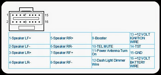
Sony Car Stereos _ XR-7300, XR-7200, XR-7201, XR-7202, XR-7400,  XR-3700RDS, XR-3750, XR-3690RDS, XR-6700RDS, XR-C700, MDX-U1RDS, XR-7082 _  & Others - Wiring Details

SONY XR-7300, XR-7200, XR-7201, XR-7202, XR-7400 
CDX-R79VF
SONY XR-502
SONY XR-7082
SONY XR-3700RDS, XR-3750, XR-3690RDS, XR-6700RDS, XR-C700
SONY XR-7042, XR-4403
SONY CDX-5072
SONY MDX-U1RDS
SONY XR-C210, XR-C214
SONY XR-4252
Click on the tables to Magnify

HOW TO DO A HARD RESET – FAULTS AND REMEDIES - PANASONIC PLASMA TVs

$
0
0
TH65PZ850U, TH58PZ850U, TH50PZ850U, TH46PZ850U, TH58PZ800U, TH50PZ800U, TH46PZ800U, TH42PZ800U, TH50PZ80U, TH46PZ80U, TH42PZ80U, TH50PX80U, TH42PX80U, TH50PZ85U, TH46PZ85U, TH42PZ85U.
How to perform a hard reset to Panasonic Plasma TV
 Normally; a hard reset can be done by unplugging the TV from AC mains wall socket, and re-plug it back after some minutes or hours.
 To   perform HARD RESET of Plasma TV unit by pressing & holding VOL DOWN(-) on unit and MENU button on remote at the same time for about 3 seconds.  This must be done if you replace the main board of the TV.  All new A boards supplied from factory needs to be initialized.  
 After the main board replacement. once AC power cord is plugged in, unit will turn on by itself. Depends on factory settings, unit will either display Video, Component or Tuner icon. After few seconds, screen will change to service mode automatically.  NOTE: Since unit is in service mode, only buttons 1, 2, 3 or 4 on remote are working (rest of buttons are nonfunctional).  After hard reset, confirm if Plasma TV powers ON in user mode and check overall functionality.
FAULTS TO 46" PLASMA TVs
* The unit shuts down and power LED blinks 10 times.
> Shorted Q409 & open PR401.  Replace Q409 & PR401
Speaker box is making rattling sound;  contact with cabinet parts
* Vibration noise from left or right speaker.  Speaker box is making direct contact with cabinet parts.
> Installing mounting screw in the center of speaker box prevents from touching the cabinet parts and minimizes the risk of vibration noise.  Install screw, part number THEL049 to both speaker boxes as shown here.  Repeat the same for left speaker box.
Relay clicks then TV shuts down with power LED 10 blinks
* When AC cord plugged in, relay clicks then TV shuts down with power LED 10 blinks.
> No Vin supply to IC520 (power control IC) due to open R712 & shorted C527.
Replace R712 & C527
R712: ERJ6GEYJ4R7
C527: ECJ3YB1E475K
Picture disappears after a few minutes, but sound is OK.
* Low Ldo_5V supply to IC9800 (DC to DC Converter) due to leaky D9801.  
> Replace D9801 on the D board.
D9801:  B0JCDD000002
Shuts down with power LED 10 blinks.
* Missing 395Vdc output due to shorted Q412 & Q413 and open PR401.
> Replace Q412, Q413, PR401 & check/replace Q408 and Q409.  Note: Always confirm condition of Q408 & Q409, in some cases could be shorted.
Q412 & Q413: B1DEGQ000070
Q408 & Q409:  B1DHCD000034
PR401: K5Y502BA0001

LG1426 - 14 Inch CTV - SCHEMATIC [Circuit Diagram]

$
0
0
USED ICs - HEF4053_M37160_M61260 / M61264_LA7840_AN7522_AT24C04
CIRCUIT DIAGRAM [SCHEMATIC-Full]
CLICK ON THE SCHEMATIC TO MAGNIFY

SANYO LCD27XL2 - LCD27XL2B LCD Television (Argentina / Brazil) - SMPS SCHEMATIC

$
0
0
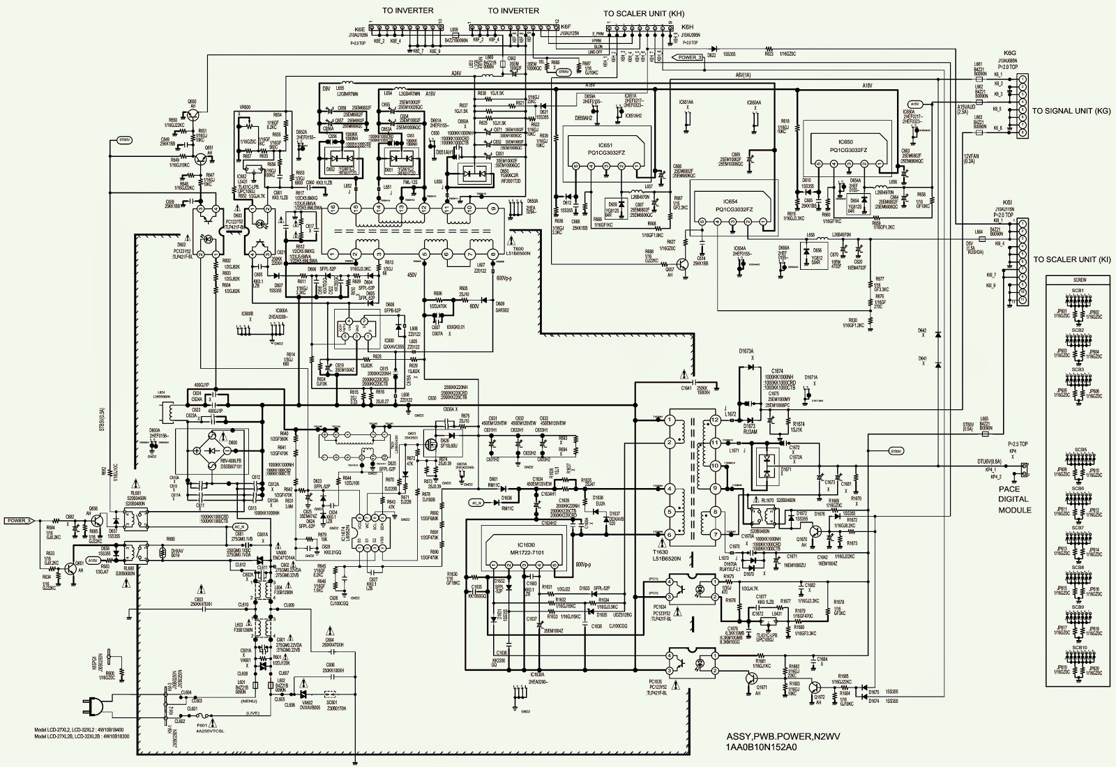
Power Supply Regulator Circuit Diagram _ Sanyo LCD27XL2 - LCD27XL2B LCD Television.
SMPS SCHEMATIC
 
CLICK ON THE SCHEMATIC TO ZOOM IN

How to enter Service Mode – Sanyo LCD-27XL2 - LCD-27XL2B – LCD TV – Option Setting

$
0
0
Sanyo LCD TV _ Option setting_Service Mode_Memory IC initialize_Service mode adjustment procedure
OPTION SETTING
After replacing Memory IC (IC801)
The memory IC (IC802) stores the option data of TV set and service adjustments data for each circuit, therefore, when the memory IC is replaced, it should be programmed to the following settings.
How to enter the Option Setting Mode
Press and hold the MUTE button on the remote control and press the CHANNEL DOWN (P) button on the front
control panel of the TV. The option window will appear on the screen.
How to make the Option Setting
Select desired option item by pressing the CHANNEL UP or DOWN button.
To switch the option mode, use the VOLUME + or - button.
The data which is set in the option mode is stored into the memory IC automatically.
To exit from the Option Mode
Press the MENU button or turn off the TV set by pressing the Power ON/OFF button.
How to enter the Service Menu
Press and hold the SOUND button of the remote control and press the CHANNEL DOWN (P▼) button on the front control panel of the TV
The Main menu of service mode will be displayed.
{Do not attempt to adjust service adjustments not listed otherwise it may cause loss of performance and for correct operation.}
How to select the service section and service item and change data value
To select Service Section: Press the Cursor ▲/ button on the remote control hand set, and press the VOLUME + button to enter the Sub menu.
To change data value: Select service item by pressing the Cursor  ▲/ and change data value by pressing the VOLUME + or - button.  (To return to the Main menu, press the MENU button.)
To exit from the Service Menu
Press the MENU button repeatedly or turn off the TV set by pressing the Power ON/OFF button.
How to Initialize the Memory IC
To initialize the Memory IC (IC802), press and hold the IMAGE button on the remote control, then press the CHANNEL DOWN button on the front panel of the TV set and then turn the Mains switch off and on. The initialization is now completed.  When initialized the memory IC and all of the setting data (option data and service adjustment data) stored in the IC are reset to the default value. It is necessary to set the option settings and readjust the service adjustments listed above.
This TV set has a built-in power supply protection circuit.  It is provided to protect the TV set in case of a power supply circuit malfunctions. When something abnormality occurs during TV reception, the TV set goes to the stand-by mode.  When operating the Protection Circuit, the Stand-by and Power Indicator will blink.
Releasing the protective circuit and restoring power supply
To release the protective circuit and restore power supply, disconnect the AC cord for a short time. This will work only if the power supply trouble was temporary. If there is permanent trouble such as a damaged circuit, power cannot be restored and the circuit will have to be repaired.

SHIVAKI STV2961PF - CRT TV - SCHEMATIC [Circuit Diagram]

$
0
0
Shivaki CRT TV _ STV2961PF _ Circuit Diagram [Full]
Circuit Diagram [Click on the Schematic to Zoom In]


LG 32LV5500 EDGE LED LCD TV - POWER and AUDIO ERROR TROUBLESHOOTING

$
0
0
Power Error_Function error_Audio error_ Troubleshooting.  LG 32LV5500 North/Latin America - Europe/Africa - Asia/Oceania.  LG 32LV5500 LED LCD TV
POWER ERROR_NO-POWER
* Check power input voltage and ST-BY 5V
For ’10 models, there is no voltage out for st-by purpose.  
When st-by, only 3.5V is normally on.
Checking method when power is ON
Power error_Off when on, off whiling viewing.  POWER OFF MODE checking method.
* Press the IN-START button of the remote controller for adjustment 
* Check the entry into adjustment item.
Audio error_No audio/Normal video
Voltage and speaker checking method when there is no audio.
* Check the contact condition of or 24V connector of Main Board.
* Measure the 24V input voltage supplied from Power Board.  (If there is no input voltage, remove and check the connector)
*Connect the tester RX1 to the speaker terminal and if you hear the Chik Chik sound when you touch the GND and output terminal, the speaker is normal.
Function error_ No response in remote controller, key error.
Remote controller operation checking method
* Check IR cable condition between IR & Main board.
* Check the st-by 3.3V on the terminal 6.
When checking the Pre-Amp when the power is in ON condition, it is normal when the Analog Tester needle moves slowly and defective when it does not move at all.
CLICK ON THE PICTURES TO MAGNIFY

SONY KDL22EX308 - KDL32EX308 Back-light Issues _ Check Points

$
0
0
KDL22EX308 - KDL32EX308 Back-light Issues _ Check Points - Sony LCD TVs.
BACK-LIGHT ISSUES
  Under normal circumstances, any failures in the back-lighting system will cause the unit to shut down. If one or more of the fluorescent back-lights fails to turn on, or if the high voltage inverter circuit fails to turn on, the unit will shut down and the standby LED will blink in groups of 6.  The first step to determine the cause of the failure is to observe the screen of the television when it is first turned on. If the back-lights turn on before the shutdown, it is likely that one of the lamps has failed to turn on and the LCD panel must be replaced.  If the back-lights do not turn on, the high voltage inverter did not start and, depending on the method of generating high voltage, replacement of the power supply or inverter board is necessary.
NO BACK-LIGHT_NO SHUT DOWN
  It is possible for a symptom of no back-lighting to occur that does not cause the television to go into protective shutdown. Dynamic dimming control of the back-lights is performed by monitoring information from the TCON board. This is in the form of data and determines the brightness level of the back-lights based on video content.  If the TCON fails to process the RGB video data, or if the dimmer data line fails, the back-lights will not turn on. Audio will be present if the selected input has it available. The television will remain on indefinitely with the green Power LED lit. If the TCON is available, it can be replaced to resolve the issue. If not, the LCD panel must be replaced.
Diagnostics History
Figure illustrates an example of the diagnostics history page. Entry to this page is achieved while the television is powered down and pressing the following buttons on the remote commander: “DISPLAY”, “5”, “VOL –“, “POWER”.  This feature is useful for failures which are intermittent or when the customer is not sure what is causing the television to shut down sometimes. Once a corrective action is determined the error events should be cleared to zero.  This is accomplished by pressing the “8” key followed by the “0” key on the remote commander.
  The drawing in Figure contains the board-to-board connector and pin information for the KDL22EX308 to identify voltages, signal and control
lines for troubleshooting purposes. Figure illustrates the same information for the KDL32EX308. All critical voltages and control signals are easily accessed at the power supply board. Use this drawing in conjunction with the previously discussed troubleshooting techniques and flowcharts for testing operating voltages and control signals.  Figure illustrates the rear of a KDL22EX308 with the cover removed.  The location of the major circuit boards and connectors for voltage checks is provided.
SONY KDL Series TVs.
KDL22EX308 TEST POINTS & BOARD LOCATIONS
KDL32EX308 TEST POINTS & BOARD LOCATIONS

SONYKDL-22EX550-26EX550-32EX650 - HOW TO REMOVE THE BACK COVER and AC COVER

$
0
0
BACK COVER REMOVAL _ SONY KDL-22EX550_KDL-22EX553_KDL-22EX555_KDL-26EX550_KDL-26EX553_KDL-26EX555_KDL-32EX650_KDL-32EX653_KDL-32EX655 - LCD Digital Color TV
* Create clearance between Bezel Assy and Rear cover with holding Rear cover.
 * Insert finger in the bottom corner.
 * Holding the rear cover so that it doesn't move, and then release the side hook.  
 Note: Without “holding Rear cover by hand”, Rear cover hooks won’t be released easily. (Possibility of damage to Rear cover hooks or Bezel Clips.)
 * Lift the lower part of the rear cover, and then release the top hook and corner hook. [When releasing the top hook from the rear cover, push the rear cover forward.]
CLICK ON THE PICTURES TO MAGNIFY

HOW TO ENTER SERVICE MODE - SONY KDL-22/26EX550,553,555,32EX650,653,655

$
0
0
KDL-22/26EX550,553,555,32EX650,653,655(AEP/UK/IT)
Following S/N Range is for (BCN)
1,000,001-1,950,000
Service Mode_V-Com adjustment_White balance adjustment_set to Shipping Condition.
SERVICE MODE
* Turn on the main power switch to place this set in standby mode.
* Press the buttons on the remote commander as follows, and entering service mode.
              DISPLAY> CHANNEL-5> VOLUME +> TV POWER
Service mode display.
Note: First of all, when you enter Service Mode, you can see “Digital” service mode.  Whenever you press “OPTIONS” or “JUMP” on remote, each service mode is changed. “Digital” > “Chassis” > “VPC”.
USING THE REMOTE CONTROL IN SERVICE MODE
After entering service mode, then turn off the power switch.
CHANGING THE DATA VALUES
Note: “Digital” service mode don’t have to Save. (except“002 MODEL” and “005 CHPRSET” category)
1. Change Data of“Digital”service mode. (except“003 DIG_SRV_MODE” category)
a. Press “2 / 5” on remote to select (up / down) category.
b. Press “1 / 4” on remote to select (up / down) Item.
c. Press “3 / 6” on remote change (up / down) data.
2.  Change Data of“Digital”service mode. (“003 DIG_SRV_MODE”category)
“003 DIG_SRV_MODE” is one category of “Digital” service mode.
Please note because this operation is special.
a. Press “2 / 5” on remote to select “003 DIG_SRV_MODE”.
b. Press “1 / 4” on remote to select (up / down) Item.
c. Press “0 / 10” on remote to select item.
d. Press number key “1”~”9” directly. “*” stamp move.
e. Press “12 / enter / select” to decide and advance next step. Press “return”, when returning on the previous page.
TO SAVE THE CHANGED DATA
1. Write data for“Chassis”or“VPC”service mode
a. Press “Mute” on remote.  It shows green “SERVICE” changes to green “WRITE”.
b. Press “0” or “enter” on remote. Green “WRITE” changes to red “WRITE”. It indicates writing is processing.
c. After a while, red “WRITE” changes to green “SERVICE”. Writing process is done at this point.
2. TV reboot is necessary for applying data change.
WHITE BALANCE ADJUSTMENT
Note: execute this adjustment if necessary.
Change Data of“VPC”service mode. (“006 WB”category)
a. Press “1” or “4” on remote to select WB adjustment menu.
b. Change data by pressing “3” or “6”. Each range of these items is 0~255.
c. Press “mute” + ”0” on remote to save the data.  “SERVICE” comment is changed to “WRITE”, indicating writing process.
d. After a while, “WRITE” comment returns to “SERVICE”, which means writing process is done.
VCOM ADJUSTMENT
Note: Execute this adjustment if necessary.
1. Change Data of“VPC”service mode.
a. Select“002 VCOM”category by pressing “2 / 5” on remote.
b. Select “000 ENABLE” item bypressing “1 / 4” on remote.
c. Change ENABLE from “0” to “1” to enable VCOM adjustment.
d. Select“002 VCOM”category by pressing “2 / 5” on remote.
e. Select “001 ADJUST” item by pressing “1 / 4” on remote.
f. Change data by pressing “3 / 6” on remote controller.
g. Finish the adjustment when the picture seems OK.
{Every time the data changed by pressing “3 / 6” Key, the VCOM pattern will display for 5s and in the mean time OSD will disappear, After the 5s period, VCOM pattern will disappear and OSD will display again.  The 5s time can be adjust by data change.
If pressing the “3/6” key again during the 5s period, the VCOM pattern display time will be extended to another 5s.}
TO SET THE SHIPPING CONDITION
* Move to“Digital”service mode.
* Press “8” on remote.
* It shows green “SERVICE” changes to green “RST-”.
* Press “mute” on remote.  Added green “EXE” after green “RST-”.
* Press “0” on remote. Green “EXE-RST” changes to red “EXE-RST”. It indicates writing is processing.  After a while, red “EXE-RST” changes to green “SERVICE”.  And all LED lights.
Writing process is done at this point.
You can set to shipping condition w/o entering Service Mode.
> “Cursor Up” on remote + “Power Key” on Front panel.


PHILIPS 32PFL3506/F7 - 32PFL3000/F8 -SERVICE MODE-INITILIZATION-POWER_INVERTER SCHEMATIC DIAGRAM

$
0
0
How to enter service mode - How to initialize - Main power & back-light Inverter CBA circuit diagram - Philips 32PFL3506/F7 - 32PFL3000/F8
SERVICE MODE
* Turn the power on.
* Press [MENU] button to display Setup menu.
* Select “Features”.
* Select “Current Software Info”.
* Press [0], [6], [2], [5], [9], [6] and [INFO] buttons on the remote control unit in this order. The following screen appears.
HOW TO IINITIALIZE
The purpose of initialization is to place the set in a new out of box condition. The customer will be prompted to select a language and program channels after the set has been initialized.
To put the program back at the factory-default, initialize the LCD TV using the following procedure.
Turn the power on.
* Enter the service mode. [To cancel the service mode, press [Power] button on the remote control unit.]
* Press [INFO] button on the remote control unit to initialize the LCD television.
* "INITIALIZED" will appear in the upper right of the screen. "INITIALIZED" color will change to green from red when initializing is completed.
MAIN POWER SUPPLY [SMPS] SCHEMATIC

BACK-LIGHT INVERTER SCHEMATIC
CLICK ON THE PICTURES TO MAGNIFY

VINVERTH VH32A5 - LCD TV - My Service Experience - Today the 8th Jan:2015

$
0
0
Vinverth VH32A5 - LCD TV - Dead set_Liquid spilled inside.
Faults occurred.
> Fuse blown [4Amp 250v]
> MOSFET5N50C at the main power regulator board [SMPS] damaged.
SMPS PWB _ FSP180-4H02
Main DIGITAL BOARD_ TM30G-V1.0
  Before replacing the fuse with an other, checked all the other components at the SMPS board for further damage.  Nothing fount abnormal, except a short circuit at the DC [rectified] voltage noticed. Soldered out the switching MOSFET 5N50C.  No short circuit measured.  On checking, the plastic body of the MOSFET has burned out and carbon particles accumulated there, causing a conduction path through the fixing screw to the heat sink metal; at the screw point.  I've illustrated the damage occurred to MOSFET in detail here.  Very rare fault indeed.  Might be of arcing due to water spill inside the set; I assume.  Replaced the MOSFET with a new one, no short circuit detected, inserted the fuse, switched the set On; OK.
See the component location and occurred damage to it
Damage to the component.
Click on the pictures to Zoom In

SAMSUNG LA32C450 - LA26C450 - LA22C450 - HOW TO ENTER SERVICE MODE - TROUBLESHOOTING

$
0
0
LA22C450E1 - LA26C450E1 - LA32C450E1 _SAMSUNG LCD TV - Service Mode_Troubleshooting
HOW TO ENTER SERVICE MODE 
> Turn the power off and set to stand-by mode
> Press the remote buttons in this order to turn the set on.
> The set turns on and enters service mode. This may take approximately 20 seconds.
> Press the Power button to exit and store data in memory.  -
If you fail to enter service mode, repeat steps 1 and 2 above.
Initial SERVICE MODE DISPLAY State
How to enter the hidden factory mode.
a. into the factory mode
b. move the tap to Advanced
c. key input : 0 + 0 + 0 + 0 ** hidden menu : Advanced.
Buttons operations within Service Mode
Direction Keys UP/DN - Item Selection by Moving the Cursor
Direction Keys L/R - Data Increase / Decrease for the Selected Item
Source - Cycles through the active input source that are connected to the unit.
FAULTS & CHECKS
No Power (SX1)
The LEDs on the front panel do not work when connecting the power cord.   The SMPS relay does not work when connecting the power cord.   The units appear to be dead.
The IP relay or the LEDs on the front panel does not work when connecting the power cord if the cables are improperly connected or the Main Board or SMPS is not functioning. In this case, check the following:
* Check the internal cable connection status inside the unit.
* Check the fuses of each part.
* Check the output voltage of SMPS.
* Replace the Main Board.
Audio is normal but no picture is displayed on the screen.
* Check the PC source.  Check the IC1102(SX1).
* Check the HDMI source.  Check the IC1102(SX1) , Check the HDMI switch.
* Check the Tuner CVBS source
* Check the M-star
* Check the Video Source
Video is normal but there is no sound.
* When the speaker connectors are disconnected or damaged.
* When the sound processing part of the Main Board is not functioning.
* Speaker defect.
No Power (X4)
The LEDs on the front panel do not work when connecting the power cord.  The SMPS relay does not work when connecting the power cord.  The units appear to be dead.
The IP relay or the LEDs on the front panel does not work when connecting the power cord if the cables are improperly connected or the Main Board or SMPS is not functioning.
* In this case, check the following:
* Check the internal cable connection status inside the unit.
* Check the fuses of each part.
* Check the output voltage of SMPS.
* Replace the Main Board.
No Video_Analog PC signal (X4)
Audio is normal but no picture is displayed on the screen.
* Check the PC source
* Check the Arsenal, Check the Chelsea.
This may happen when the LVDS cable connecting the Main Board and the Panel is disconnected.
No video_HDMI1, 2, 3, 4 - Digital signal (X4)
Check the HDMI source.
Check the HDMI switch, Check the Chelsea.
No Video_Tuner - CVBS (X4)
Check the Tuner CVBS source.
Check the Tuner, Check the Chelsea.
No Video_Video CVBS (X4)
Audio is normal but no picture is displayed on the screen.
* Check the Video CVBS source
* Check the Chelsea.
This may happen when the LVDS cable connecting the Main Board and the Panel is disconnected.
No Video_Component (X4)
Check the Component source
Check the Chelsea.
No Sound (X4)
Video is normal / when the speaker connectors are disconnected or damaged.
When the sound processing part of the Main Board is not functioning.
Speaker defect.


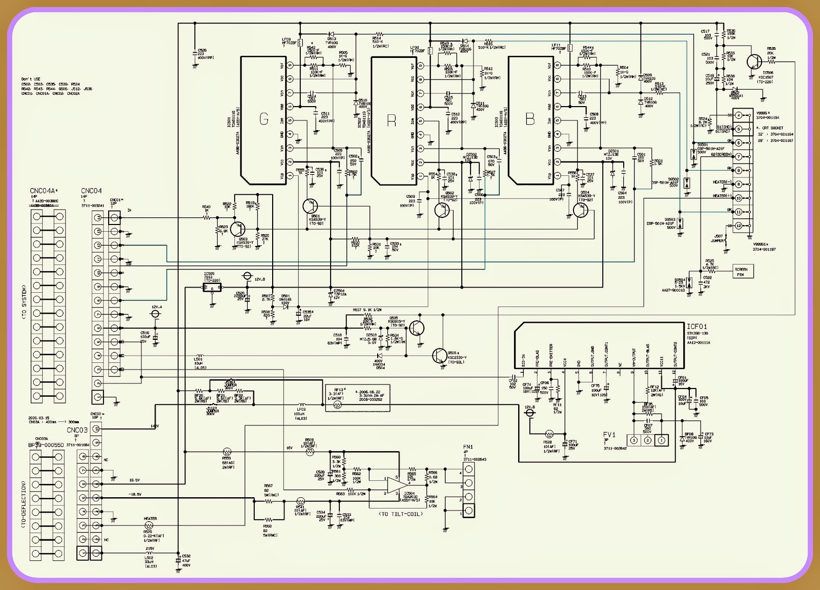
SAMSUNG CRT TV-WS-32Z30HPQ - SMPS (Power) and Deflection - Circuit Diagram (Schematic)

$
0
0
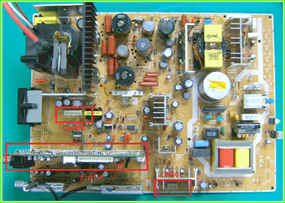
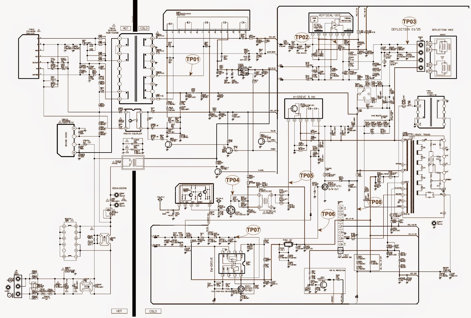
Samsung WS32Z30 - SLIM CRT TV - Power _ Deflection _ Ass'y Feature box & CRT base card Circuit Diagram.
POWER & DEFLECTION ASSY'
CN601  > This is a 4 pin port connected to the Speaker, and sends the signal from the AMP to the speakers.
CN403  > This is a 8 pin port connected to the CRT Board and supplies 200V, +16V, -16V and Heater voltage.
GT804
  > This is a ground port to prevent high voltage due to lighting.
CN802
  > This is a 3 pin port connected to the AC power cable. It is connected to the power cable socket.
GT805
, GT806  > This is a port connected to the D-Coil surrounding the CRT.
SCHEMATIC-SMPS
ASSEMBLY FEATURE-BOX
CN07 > This is a 14 pin port connected to the CRT Assy's, and outputs final R/G/B signals to the CRT Ass'y.
In addition, it outputs the Tilt, VM, and Power signals for the CRT Drive.
CN05 > This is a 4 pin port connected to the Control Ass'y, and receives TV/Video, Menu, Ch Up/Down and Vol -/+ signals.
CN04 > This is a 6 pin port connected to the Master Ass'y, and receives Master Power On/Off, and IR signals.
CN03 > This is a 8 pin port connected to the Side AV, and receives S-Video2 and AV4 external inputs.
CRT DRIVE CARD
GT501, GT502, GT505, GT506> This is a port connected to the TBC-Wire and plays the role of CRT ground.
GT503, GT504> This is a port for countermeasures against compulsory discharges and is connected to the Main Board.
CNC04> This is a port to receive the R/G/B output signals from the Feature Box.
CNC02> This is a port that receives power for the CRT and AMP from the Main Board.
FV1> A port to connect the VM signal to the DY Ass'y.
FN1
> A port to connect signals to the Tilt Coil and is regarded for the screen slant adjustment.
CLICK ON THE PICTURES TO MAGNIFY

PANASONIC PLASMA TV - VERTICAL LINE FAULT PROBLEMS - TH-P65 – TH-P55 – TH-P50 – TH-P42

$
0
0
PANASONIC Plasma TVs - TH-P65 _ TH-P55 _ TH-P50 _ TH-P42 - Vertical Line Fault & Troubleshooting
RAINBOW VERTICAL BARS
  This symptom is very likely to be a A board defect; but for 2011 model the Panel and C board defect is a high possibility.  One of the data driver IC is defective and 3.3V goes down, the other data driver ICs don’t work correctly.  Because 3.3V is common for all data driver ICs.  Vda line is isolated due to resistor being open.
  Check by displaying some images.  If the position of color bars changes and there are some black blocks, the data driver IC is defective.  If there is no black bar block, check the connection of cables. [Between A and C boards].  If the trouble persists, the A board could be defective.
TROUBLESHOOT
EXAMPLES OF OTHER IMAGES
CLICK ON THE PICTURES TO ZOOM IN

HOW TO ENTER SERVICE MODE - PHILIPS 26PFL5332D-32PFL5332D-37PFL5332D-42PFL5332D

$
0
0
Philips 26PFL5332D_32PFL5332D_37PFL5332D_42PFL5332D _ Service Mode _ Option Codes _ Audio Amplifier Circuit Diagram
HOW TO ACTIVATE SAM [Service Alignment Mode]
  Via a standard RC transmitter: key in the code “062596” directly followed by the “INFO” button. After activating SAM with this method a service warning will appear on the screen, you can continue by pressing the red button on the RC.
HARDWARE INFORMATION
A. VIPER SW Version. Displays the software version of the VIPER software (main software) (example: EJ30U_0.77.0.0 = AAAAB_X.Y.W.Z_NNNNN).>  AAAA= the chassis name.>  B= the region: A= AP, E= EU, L= Latam, U = US.>  X.Y.W.Z= the software version, where X is the main version number (different numbers are not compatible with one another) and Y is the sub version number (a higher number is always compatible with a lower number). The last two digits are used for development reasons only, so they will always be zero in official releases.>  NNNNN= last five digits of 12nc code of the software.
B. SBY PROC Version. Displays the software version of the stand-by processor.C. Production Code. Displays the production code of the TV, this is the serial number as printed on the back of the TV set. Note that if an NVM is replaced or is initialized after corruption, this production code has to be re-written to NVM. ComPair will foresee in a possibility to do this.>  Operation Hours.Displays the accumulated total of operation hours (not the stand-by hours). Every time the TV is switched "ON/OFF", 0.5 hours is added to this number.>  Errors.(Followed by maximal 10 errors). The most recent error is displayed at the upper left (for an error explanation see paragraph “Error Codes”).>  Defective Module. Here the module that generates the error is displayed. If there are multiple errors in the buffer, which are not all generated by a single module, there is probably another defect. It will then display the message “UNKNOWN” here.>  Reset Error Buffer. When you press “cursor right” and then the “OK” button, the error buffer is reset.>  Alignments. This will activate the “ALIGNMENTS” submenu.>  Dealer Options. Extra features for the dealers.>  Options. Extra features for Service.>  Initialize NVM. When an NVM was corrupted (or replaced) in the former EMG based chassis, the microprocessor replaces the content with default data (to assure that the set can operate). However, all preferences and alignment values are gone now, and option numbers are not correct.  Therefore, this was a very drastic way. In this chassis, the procedure is implemented in another way: The moment the processor recognizes a corrupted NVM, the “initialize NVM” line will be highlighted. Now, you can do two things (dependent of the service instructions at that moment):
#  Save the content of the NVM via ComPair for development analysis, before initializing. This will give the Service department an extra possibility for diagnosis (e.g. when Development asks for this).
#  Initialize the NVM (same as in the past, however now it happens conscious).
{When you have a corrupted NVM, or you have replaced the NVM, there is a high possibility that you will not have picture anymore because your display option is not correct. So, before you can initialize your NVM via the SAM, you need to have picture and therefore you need the correct display option. To adapt this option, you can use ComPair (the correct HEX values for the options can be found in the table below) or a method via a standard RC (described below).}
Note:Changing the display option via a standard RC
  Key in the code “062598” directly followed by the “MENU” button and by “XXX” (where XXX is the 3 digit decimal display option code as mentioned in the first column of the next table).
Make sure to key in all three digits, also the leading zero’s. If the above action is successful, the front LED will go out as an indication that the RC sequence was correct. After the display option is changed in the NVM, the TV will go to the Stand-by mode. If the NVM was corrupted or empty before this action, it will be initialized first (loaded with default values). This initializing can take up to 20 seconds.
 Store. All options and alignments are stored when pressing “cursor right” and then the “OK” button* SW Maintenance.
SW Events. Not useful for service purposes. In case of specific software problems, the development department can ask for this info.
HW Events. Not functional at the moment this manual is released, description will be published in an update manual if the function becomes available.* Upload to USB. Write the channel list and the settings to a USB device.* Download from USB. Retrieve the channel list and the settings from a USB device.
HOW TO NAVIGATE
>  In SAM, you can select the menu items with the “CURSOR UP/DOWN” key on the RC transmitter. The selected item will be highlighted. When not all menu items fit on the screen, move the “CURSOR UP / DOWN” key to display the next / previous menu items.
>  With the “CURSOR LEFT/RIGHT” keys, it is possible to:  (De-activate the selected menu item.
TO EXIT THE SERVICE ALIGNMENT MODE
Use one of the following methods:
1. Press the “MENU” button on the RC transmitter.
2. Switch the set to STAND-BY via the RC transmitter.
[As long as SAM is activated, it is not possible to change a channel. This could hamper the White Point alignments because you cannot choose your channel/frequency any more.
Workaround: after you have sent the RC code “062596 INFO” you will see the service-warning screen, and in this stage it is still possible to change the channel (so before pressing the “OK” button).]
DISPLAY OPTION CODE_FOR ALL PHILIPS (FTV) CHASSIS
AUDIO AMPLIFIER SCHEMATIC
CLICK ON THE PICTURES TO MAGNIFY

PHILIPS 26PFL5332D-32PFL5332D-37PFL5332D-42PFL5332D _ Error Codes – LED blinking codes & fault finding.

$
0
0
Error Codes – LED blinking codes _ fault finding -  PHILIPS 26PFL5332D-32PFL5332D-37PFL5332D-42PFL5332D
ERROR CODES
The error code buffer contains all detected errors since the last time the buffer was erased. The buffer is written from left to right, new errors are logged at the left side, and all other errors shift one position to the right.  When an error has occurred, the error is added to the list of errors, provided the list is not full or the error is a protection error.  When an error occurs and the error buffer is full, then the new error is not added, and the error buffer stays intact (history is maintained), except when the error is a protection error.  To prevent that an occasional error stays in the list forever, the error is removed from the list after 50+ operation hours.  When multiple errors occur (errors occurred within a short time span), there is a high probability that there is some relation between them. 
> Errors detected by the Stand-by Processor. These errors will always lead to protection and an automatic start of the blinking LED for the concerned error (The Blinking LED Procedure). In these cases SDM can be used to start up.
> Errors detected by VIPER that lead to protection. In this case the TV will go to protection and the front LED will blink at 3 Hz. Further diagnosis via service modes is not possible
here.
> Errors detected by VIPER that do not lead to protection. In this case the error can be read out via ComPair, via the blinking LED method, or in case you have picture, via SAM.
HOW TO READ THE ERROR BUFFER
Use one of the following methods
* On screen via the SAM (only if you have a picture). E.g.:
> 00 00 00 00 00: No errors detected
> 06 00 00 00 00: Error code 6 is the last and only detected error
> 09 06 00 00 00: Error code 6 was first detected and error code 9 is the last detected error
*  Via the blinking LED procedure (when you have no picture).
*  Via com-pair.
HOW TO CLEAR THE ERROR BUFFER
Use one of the following methods
* By activation of the “RESET ERROR BUFFER” command in the SAM menu.
* With a normal RC, key in sequence “MUTE” followed by “062599” and “OK”.
* If the content of the error buffer has not changed for 50+ hours, it resets automatically.
ERROR BUFFER
In case of non-intermittent faults, clear the error buffer before you begin the repair (before clearing the buffer, write down the content, as this history can give you significant information).  This to ensure that old error codes are no longer present.  If possible, check the entire contents of the error buffer. In some situations, an error code is only the result of another error code and not the actual cause (e.g., a fault in the protection detection circuitry can also lead to a protection).
There are several mechanisms of error detection
* Via error bits in the status registers of ICs.
* Via polling on I/O pins going to the stand-by processor.
* Via sensing of analogue values on the stand-by processor.
* Via a “not acknowledge” of an I2 C communication
Take notice that some errors need more than 90 seconds before they start blinking. So in case of problems wait 2 minutes from start-up onwards, and then check if the front LED is blinking.
ERROR CODES
Error 1 (I2 C bus 1 blocked)
When this error occurs, the TV will go to protection and the front LED will blink at 3 Hz.  Now you can partially restart the TV via the SDM shortcut pins on the SSB. Depending on the software version it is possible that no further diagnose (error code read-out) is possible. With the knowledge that only errors 1, 2, 4, and 63 result in a 3 Hz blinking LED, the range of possible defects is limited.
Error 2 (I2 C bus 2 blocked).
When this error occurs, the TV will go to protection and the front LED will blink at 3 Hz.  Now you can partially restart the TV via the SDM shortcut pins on the SSB. Due to hardware restriction (I2 C bus 2 is the fast I2 C bus) it will be impossible to start up the VIPER and therefore it is also impossible to read out the error codes via ComPair or via the blinking LED method. With the knowledge that only errors 1, 2, 4, and 63 result in a 3 Hz blinking LED, the range of possible defects is limited.  When you have restarted the TV via the SDM shortcut pins, and then pressed "CH+" on your remote control, the TV will go to protection again, and the front LED blink at 3 Hz again. This could be an indication that the problem is related to error 2.
Error 3 (I2 C bus 3 blocked).
There are only three devices on I2 C bus 3: VIPER, Stand-by Processor, and NVM. The Stand-by Processor is the detection device of this error, so this error will only occur if the VIPER or the NVM is blocking the bus. This error will also be logged when the NVM gives no acknowledge on the I2 C bus (see error 44). Note that if the 12 V supply is missing (connector 1M46 on the SSB), the DC/DC supply on the SSB will not work. Therefore the VIPER will not get supplies and could block I2 C bus 3. So, a missing 12 V can also lead to an error 3.
Error 4 (I2 C bus 4 blocked).
Error 4 is displayed in SAM. No protection.
Error 5 (Viper doesn’t boot). 
This error will point to a severe hardware problem around the VIPER (supplies not OK, VIPER completely dead, I2 C link between VIPER and Stand-by Processor broken, etc. ...).
Error 7 (8.6 V error). 
Except a physical problem with the 8.6 V itself, it is also possible that there is something wrong with the Audio DC Protection: see paragraph "Hardware Protections" for this.
Error 12 (12 V error). 
Except a physical problem with the 12 V itself, it is also possible that there is something wrong with the Audio DC Protection: see paragraph "Hardware Protections" for this.
• Error 14 (Audio supply). This error is triggered in case of too low voltage of the audio supplies and therefore a drop of the audio supply voltage of below approx. 9 V per supply rail (or lower than 18 V rail to rail). Also a DC voltage of higher than 1 V DC on the speakers will lead to protection and error 14 blinking. For LCD sets this circuit can be found on schematic SA3, for PDP sets this can be found on schematic C. It should be noted that for 26-inch models there is only a supply link between the amplifiers and the stand-by μC whereas in all other models this link is implemented by Audio-Prot line pin 7 on 1 M02.
Error 18 (MPIF1). 
Error 18 is displayed in SAM. No protection.
Error 21 (HDMI switch). 
Error 21 is displayed in SAM. No protection.
Error 25 (Supply fault). 
When this error occurs, the TV will go to protection and the front LED will blink at 3 Hz.
Error 29 (AVIP1). 
This error will probably generate extra errors. You will probably also see errors 32 (MPIF) and error 31 (AVIP 2). Error 29 and 31 will always be logged together due to the fact that both AVIPs are inside the PNX2015 and are on the same I2 C bus. In this case start looking for the cause around AVIP (part of PNX2015).
Error 31 (AVIP2). See info on error 29.
Error 34 (Tuner 1). 
When this error is logged, it is not sure that there is something wrong with the tuner itself. It is also possible that there is something wrong with the communication between channel decoder and tuner. 
Error 37 (Channel decoder). 
This error will always log error 34 (tuner) extra. This is due to the fact that the tuner I2C bus is coming from the channel decoder.
Error 44 (NVM). 
This error will never occur because it is masked by error 3 (I2 C bus 3). The detection mechanism for error 3 checks on an I2 C acknowledge of the NVM. If NVM gives no acknowledge, the stand-by software assumes that the bus is blocked, the TV goes to protection and error 3 will be blinking.
Error 53. 
This error will indicate that the VIPER has started to function (by reading his boot script, if this would have failed, error 5 would blink) but initialization was never completed because of hardware peripheral problems (NAND flash, ..) or software initialization problems.  Possible cause could be that there is no valid software loaded (try to upgrade to the latest main software version).
BLINKING LED PROCEDURE
How to Activate
Use one of the following methods:
* Activate the SDM. The blinking front LED will show the entire contents of the error buffer (this works in “normal operation” mode).
* Transmit the commands “MUTE” - “062500” - “OK” with a normal RC. The complete error buffer is shown.  Take notice that it takes some seconds before the blinking LED starts.
* Transmit the commands “MUTE” - “06250x” - “OK” with a normal RC (where “x” is a number between 1 and 5). When x= 1 the last detected error is shown, x= 2 the second last error, etc.... Take notice that it takes some seconds before the LED starts blinking.
The blinking LED procedure can be split up into two situations
* Blinking LED procedure in case of a protection detected by the stand-by processor. In this case the error is automatically blinked. This will be only one error, namely the one that is causing the protection. Therefore, you do not have to do anything special, just read out the blinks. A long blink indicates the decimal digit; a short blink indicates the units.
* Blinking LED procedure in the “ON” state. Via this procedure, you can make the contents of the error buffer visible via the front LED. This is especially useful for fault finding, when there is no picture.
When the blinking LED procedure is activated in the “ON” state, the front LED will show (blink) the contents of the error-buffer.  Error-codes > 10 are shown as follows
1.“n” long blinks (where “n” =1 - 9) indicating decimal digit,
2. A pause of 1.5 s,
3.“n” short blinks (where “n”= 1 - 9),
4. A pause of approx. 3 s.
5. When all the error-codes are displayed, the sequence finishes with a LED blink of 3 s,
6. The sequence starts again.
Example:Error 12 9 6 0 0.
After activation of the SDM, the front LED will show:
1. 1 long blink of 750 ms (which is an indication of the decimal digit) followed by a pause of 1.5 s,
2. 2 short blinks of 250 ms followed by a pause of 3 s,
3. 9 short blinks followed by a pause of 3 s,
4. 6 short blinks followed by a pause of 3 s,
5. 1 long blink of 3 s to finish the sequence,
6. The sequence starts again.
PROTECTIONS
Software Protections
Most of the protections and errors use either the stand-by microprocessor or the VIPER controller as detection device.  Since in these cases, checking of observers, polling of ADCs,
filtering of input values are all heavily software based, these protections are referred to as software protections.  There are several types of software related protections, solving
a variety of fault conditions:
> Protections related to supplies: check of the 12V, +5V,+8V6, +1.2V, +2.5V and +3.3V.
> Protections related to breakdown of the safety check mechanism. E.g. since a lot of protection detection are done by means of the VIPER, failing of the VIPER communication will have to initiate a protection mode since safety cannot be guaranteed anymore.
The detection of a supply dip or supply loss during the normal playing of the set does not lead to a protection, but to a cold reboot of the set.
Protections during Start-up
During TV start-up, some voltages and IC observers are actively monitored to be able to optimize the start-up speed, and to assure good operation of all components. If these monitors do not respond in a defined way, this indicates a malfunction of the system and leads to a protection.
HARDWARE PROTECTIONS
There is one hardware protection in this chassis: “Audio DC Protection”. This protection occurs when there is a DC voltage on the speakers. In that case the main supply is switched
"OFF", but the stand-by supply is still working.  In case of LCD supplies, the 12V supply will drop. This will be detected by the stand-by processor, which will start blinking the 12 V error (error 12).
Repair Tip
* It is also possible that you have an audio DC protection because of an interruption in one or both speakers (the DC voltage that is still on the circuit cannot disappear through the speakers).
FAULT FINDING TIPS

> Symptom: +1V2, +2V5, and +3V3 not present (even for a short while ~10ms).
1. Check 12V availability (fuse 1U01, resistor 3U22, power MOSFETs) and enable signal ENABLE-1V2 (active low).
2. Check the voltage on pin 9 (1.5 V).
3. Check for +1V2 output voltage short-circuit to GND that can generate pulsed over-currents 7-10 A through coil 5U03.
4. Check the over-current detection circuit (2U12 or 3U97 interrupted).
> Symptom: +1V2 present for about 100 ms. Supplies +2V5 and +3V3 not rising.
1. Check the ENABLE-3V3 signal (active "low").
2. Check the voltage on pin 8 (1.5 V).
3. Check the under-voltage detection circuit (the voltage on collector of transistor7U10-1 should be less than 0.8 V).
4. Check for output voltages short-circuits to GND (+3V3, +2V5 and +2V5D) that generate pulsed over-currents of 7-10 A through coil 5U00.
5. Check the over-current detection circuit (2U18 or 3U83 interrupted).
> Symptom: +1V2 OK, but +2V5 and +3V3 present for about 100 ms.
Cause: The SUPPLY-FAULT line stays "low" even though the +3V3 and +1V2 is available. The Stand-by
Processor is detecting that and switches all supply voltages "OFF".
1. Check the drop voltage across resistor 3U22 (this could be too high)
2. Check if the +1V2 or +3V3 are higher than their normal values. This can be due to defective DC feedback of the respective DC/DC converter (3U18 or 3UA7).
> Symptom: +1V2, +2V5, and +3V3 look okay, except the ripple voltage is increased (audible noise can come from the filtering coils 5U00 or 5U03).
Cause: Instability of the frequency and/or duty cycle of one or both DC/DC converters.
– Check resistor 3U06, the decoupling capacitors, the AC feedback circuits (2U20 + 2U21 + 3U14 + 3U15 for +1V2 or 2U19 + 2U85 + 3U12 + 3U13 for +3V3), the compensation capacitors 2U09, 2U10, 2U23 and 2U73, and IC 7U00. {If fuse 1U01 is broken, this usually means a pair of defective power MOSFETs (7U01 or 7U03). Item 7U00 should be replaced as well in this case.

NETWINNER and NETSTATION 600 - 1200Bi _ SCHEMATIC [Circuit Diagram)

$
0
0
SCHEMATICS
CLICK ON THE SCHEMATICS TO ZOOM IN

Viewing all 2033 articles
Browse latest View live


<script src="https://jsc.adskeeper.com/r/s/rssing.com.1596347.js" async> </script>