Quantcast
Channel: Electro help
Viewing all 2033 articles
Browse latest View live

MARANTZ - PM6010F - STEREO AMPLIFIER - SCHEMATIC

$
0
0
Used ICs - TMP47C200BN_LB1630_NJN206800_AN7062P_TA7317P
ADJUSTMENT OF IDLING CURRENT TO POWER AMPLIFIER
* Before switching the power ON, set the master volume control to the minimum position and the balance volume to the center positions. Also set semi-fixed
resistors R755(L ch) and R756(R ch) on PCB P701 to the center positions.
* Each of the cement resistors R767(L ch) and R768(R ch) on the PCB P701 is provided with three test points.  Connect a digital voltmeter, set for the DC voltage
input, to the test points at the two extremities of the three test points of R767 or R768.
* After the setup above, switch the power ON, and adjust semi-fixed resistors R755(L ch) and R756(R ch) on PCB P701 according to the digital voltmeter reading. The target setting value is 10 mV(50 mA) for both the L ch and R ch.
SYSCON - SCHEMATIC & PWB
MAIN AMP - SCHEMATIC & PWB
CLICK ON THE PICTURES TO MAGNIFY


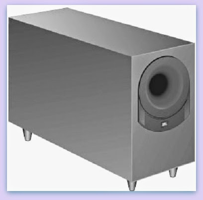
JBL SUB350 – SCHEMATIC DIAGRAM - Exploded View - parts list

$
0
0
JBL SUB350 Dolby Pro-Logic Surround Amplifier_Sub-woofer - Circuit Diagram
SPECIFICATIONS
Total System Output 200 watts
Front channels – 35 watts x 3 @ .1% THD
Surround channels – 15 watts x 2 @.1% THD
Subwoofer – 65 watts @ .1% THD
Frequency response 35Hz – 20kHz
S-N ratio 90 dB
Input Impedance 20k Ohms
Input Sensitivity 1500mV
SUB350
Dimensions 15 1/8 x 13 x 14 ½” (384 x 330 x 368mm)
Weight 34.5 lbs. (15.7 kg)
EXPLODED VIEW
SCHEMATIC DIAGRAM
CLICK ON THE PICTURES TO MAGNIFY
If there is no sound from any of the speakers, check the following
* Make sure the subwoofer is plugged into an active AC wall outlet.
* Make sure the Master Power Switch, located on the rear of the subwoofer, is in the “ On/Standby” position.
* Make sure there is a source – for example, a VCR or television – hooked up to the TV or tape/aux input jacks on The Source.
* Make sure that the program material is playing.
* Recheck the hookup connections. If most of the sound comes from the center-channel speaker, with little or no information from the surround channels, note the following:
Although most of today’s televisions are equipped with stereo audio output jacks, some stereo televisions have poor audio sections and are unable to provide a Dolby Pro Logic encoded signal. In the unlikely event that you experience this problem, connecting the audio outputs from your hi-fi VCR, laser disc player, DVD player, or satellite receiver directly to one of the inputs on The Source will provide a proper audio signal and allow you to enjoy true Dolby Pro Logic surround sound.  If there is no sound from the surround speakers or sound is very low, check the following:
* Check all connections between the amplifier and each of the speakers.
* Raise the surround volume from the remote control.
* Make sure the TV show or movie you are watching is recorded in Dolby Surround.  If there is no sound from the center speaker, check the following:
* Make sure that the processor is in the Pro Logic mode. If it is in Phantom or Stereo mode, the center speaker will not play.
* Check the connections between the subwoofer and the center speaker.
If you have low bass output, check the following
* Experiment with placement of the subwoofer. Remember; place the subwoofer in a corner to get maximum bass output from the system.
* Increase the level of bass, using the remote control.
* Adjust the level control on the rear of the subwoofer.  If you are having trouble picking up radio stations, check the following:
* Make sure the antenna is hooked up properly.
* Depending on your distance from the station’s transmitter, you may need to install an FM antenna on the roof or in the attic.

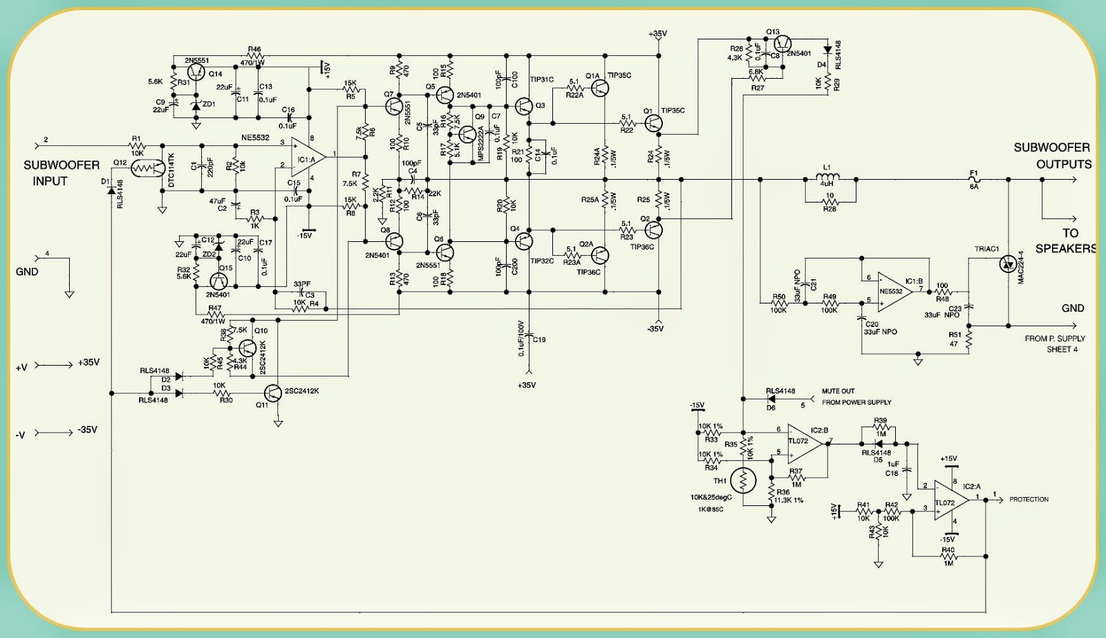
BASS 550 JBL Powered Subwoofer - SCHEMATIC (Circuit Diagram)

$
0
0
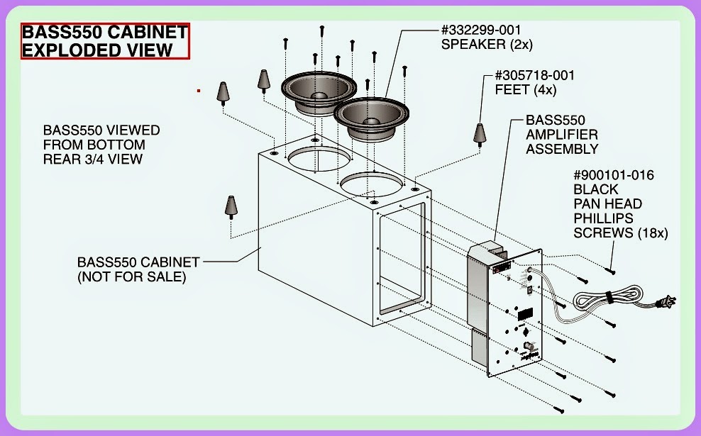
JBL Powered Subwoofer BASS550_Circuit Diagram_Exploded View
POWER SUPPLY SCHEMATIC
PRE-AMP
POWER AMP
EXPLODED VIEW
CLICK ON THE PICTURES TO MAGNIFY

LG LDS4821 DISHWASHER – WIRING DIAGRAM - ERROR CODES DISPLAYS

$
0
0
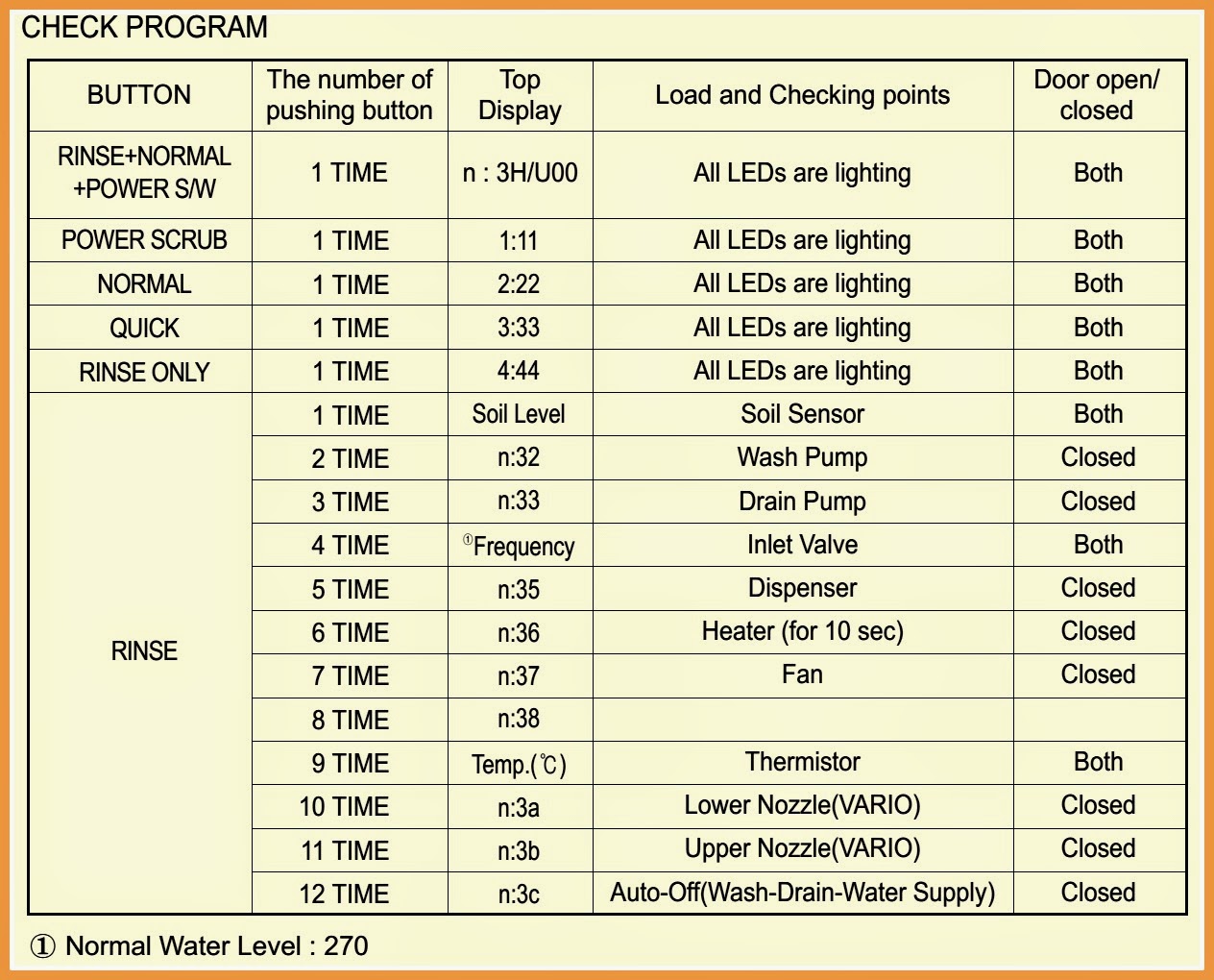
DISHWASHER – WIRING DIAGRAM -  ERROR CODES DISPLAYS  LG-LDS4821(WW,BB,ST)
WIRING DIAGRAM
CHILD LOCK CANCEL
* To cancel a running cycle, open the door, then press and hold the POWER SCRUB and NORMAL buttons together for 3 seconds. The drain pump will be activated and the cycle will be canceled.
* To lock/unlock the buttons, press QUICK and RINSE ONLY simultaneously for 3 seconds. When CHILD LOCK is set, all buttons are disabled.
TEST MODE - LDS4821 Series
ERROR DISPLAY
CLICK ON THE PICTURES TO MAGNIFY

PHILIPS 42" LCD TV - POWER SUPPLY SCHEMATIC

$
0
0
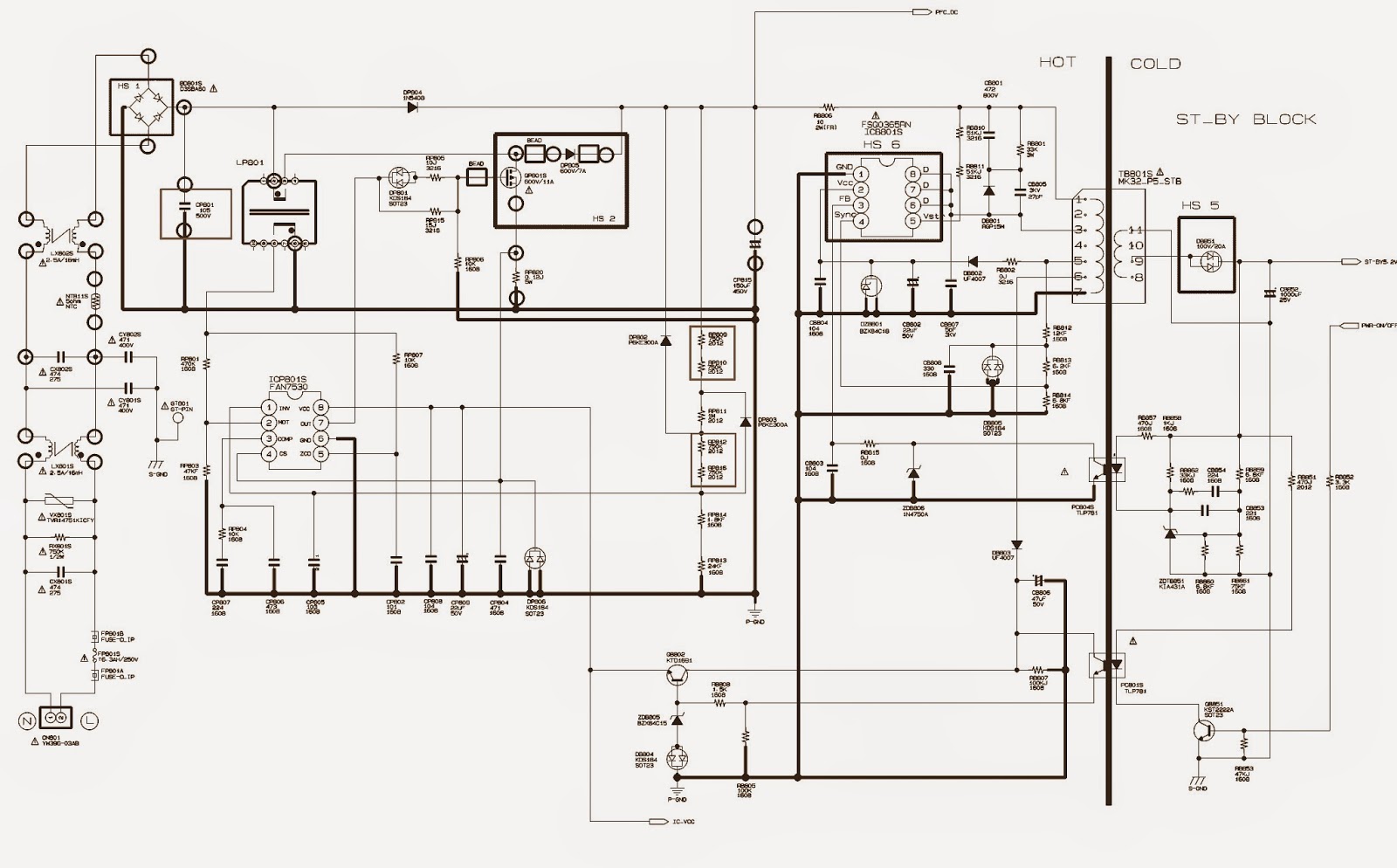
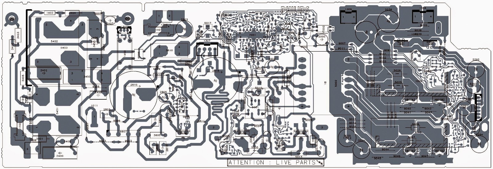
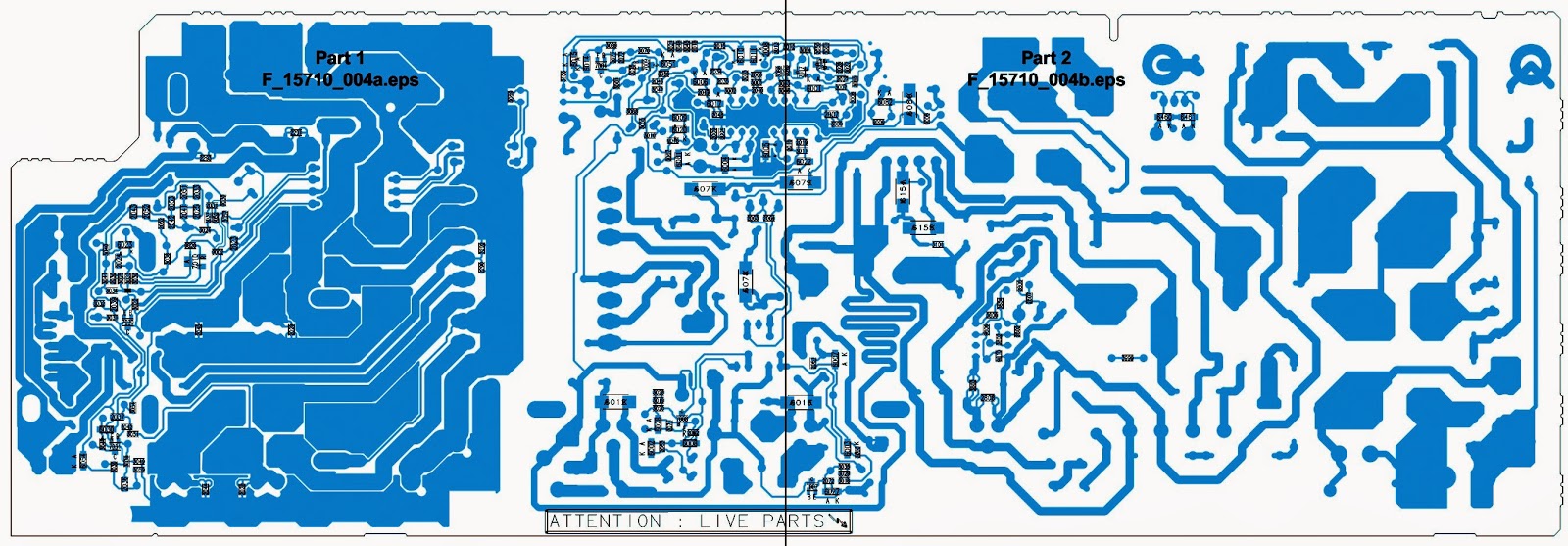
POWER SUPPLY CIRCUIT DIAGRAM [SMPS] - PHILIPS 42" LCD TV
Mains Filter & Standby Part
Switching & Output
PWB
CLICK ON THE PICTURES TO ZOOM IN

SAMSUNG LCD TV POWER SUPPLY - TYPE-BN-4400208A

$
0
0
Samsung LCD TV_SMPS _BN-4400208A
SCHEMATIC {CLICK ON THE SCHEMATICS TO MAGNIFY}

PHILIPS 37" LCD TV POWER SUPPLY [SMPS] - SCHEMATIC

$
0
0
SMPS Schematic (Circuit Diagram) - Philips 37 Inch LCD TVs
PWB
CLICK ON THE PICTURES TO MAGNIFY

32 INCH PHILIPS LCD TV POWER SUPPLY [SMPS] SCHEMATIC

$
0
0
Power Supply Regulator board circuit diagram _ Philips 32" LCD TVs.
MAINS FILTER & STANDBY
PWB & Component layout
Click on the pictures to Magnify


SIEMENS DISH-WASHER - HOW TO REPLACE CIRCULATION PUMP

$
0
0
How to replace circulation pump & Impeller to Bosch _ Siemens _ Gaggenau & Thermador Dish-washers
 The circulation pump & capacitor are accessed from the right side of the dishwasher by removing the right side panel and blocking the tank. Use same process to access heater & Apexx modules.
HOW TO REMOVE THE OUTER DOOR
> Remove six T-20 Torx inner door screws below fascia panel -- three per side (1).
> Carefully pull bottom of outer door out from dishwasher until top door tabs clear, then pull door down until it releases from dishwasher (2). Take care to not scratch outer door.
> Remove 1-piece foam or two plastic door guards (3). The plastic door guards occasionally fall out when the outer door is removed.
{Circulation pump 239144 motor is rated 120V, 60 Hz, 160W, insulation class A. Motor has an auto reset thermal protector and uses a 10μF capacitor. The fascia panel and door don’t need to be removed to access the circulation pump. However, they must be removed to completely remove the tank.}
HOW TO REMOVE THE TOE KICK
> Remove two T-20 Torx screws from toe kick (1).
> Tilt toe kick out from under dishwasher (2)
[For models UC/36 & above, toe kicks screw directly into plastic bases using longer screws.]
To remove right &left side panels
Dishwashers may have long or short side panels, depending on model. Removing the left side panel isn’t necessary for access, but allows the right side of the tank to be blocked upward.
> For models with long side panels, remove two T-20 Torx side panel screws through holes in right & left trim strips(1).
> To remove long side panels, lift panels with trim strips up and out from dishwasher(2).
> To remove short side panels, remove two T-20 Torx screws(3). To avoid damaging trim strips (while blocking tanks), slide trim strips up until they clear dishwasher bases.
To raise right side of tank for circulation pump access
> Remove one T-20 Torx screw from both rear corners holding tank to base (1) removing screw from both sides allows tank to be blocked upward.
> Remove right toe kick bracket by removing T-20 Torx screw (2).
> Remove T-20 Torx screws from front right bottom corner holding tank to base (3).
4.Remove right hinge cover(4a), release right door tension cord from hinge (4b)& remove ground wire (4c).
> Raise and block up tank as shown with strut onto base (5a), sliding a piece of wood or other solid material between the tank and base to keep tank from falling back onto base (5b)
[Don’t turn dishwashers’ upside-down for tank access. When dishwashers are turned upside-down, water can flow into the water fill assembly diaphragm and cause water to not fill properly]
> Disconnect wire harness from motor after carefully noting connections (1).
> For UC/11 & later models with softer bearing, lift up rubber straps from both sides of motor (2). For older models, lift motor up from base.
> To release plastic latch on pump/motor housing (@ 2:30 position), carefully push onto latch with screwdriver (3).
> To release motor from pump housing, twist motor to the right (clockwise). Some force may be required. Capacitor should be ~ 11:00 position (4). Pull motor out from pump housing.
{When replacing circulation pumps for softer bearing models (UC/11 & later), reusing existing front pump housings can save time by not changing hose clamps. If
desired, order #172272 hose clamps & replace entire pumps.  Don’t grab motor next to the capacitor to avoid jamming your hand on the capacitor}
COMPARING CIRCULATION PUMP VERSIONS
665510 BLDC pump (1)
* Pump, motor and control come as one unit.
* Speed changes as needed for wash cycle and washability (Variowash).
* Pump is isolated from motor, so no seal is needed and no need to loosen or replace impellers
* Used starting with UC/46 index.
442548 (“Sicasym”) pump (2)
* Most common pump. Used starting with UC/21 index. Smaller than 239144 pump.
* Used with control modules & single wire harnesses designed for Sicasym pumps. Controls have motor starter software.
* Can’tuse # 167085 impeller kit.
437345 pump for water switches (3)
* More powerful for use with water switches (Apexx & ExactWash models).
* Has separate motor starter (# 182318).
* Must use with heaters with water switches & sumps with extra filter cylinder.
* Can use # 167085 impeller kit
239144 pump (4)
* Can buy # 266511 motor separately.
* Can use # 167085 impeller kit.
{Cheater cords can’t be used to check Sicasym and BLDC pumps since they use special starters}
CLICK ON THE PICTURES TO ZOOM IN

BOSCH - SIEMENS DISHWASHERs - ERROR CODES – HEATER AND NTC REPLACEMENT

$
0
0
Gaggenau_Siemens_Theremador & Bosch dishwashers_ how to replace Heater & NTC _ Error codes.
ERROR CODES
P(X) Program codes
P0 = Functional test - used for assembly
P1 = Customer service test program
P3 = Endurance/Life test
P4 = Control coding (see “C(X)” control codes below)
E(X) Error codes
E0 = No errors
E1 = Heating error
E2 = NTC error
E3 = Filling error
E4 = Water switch cannot be positioned
E5 = Safety level reached E6 = Aqua sensor error
C(X) Control Codes
Codes C1 to C9 possible, depending on DW model.
{Pushing Cancel-Drainer Cancel-Reset buttons while dw’s are off can see codes, leading to service calls.}
ERROR CODE-1
  Occasionally dishwashers can run for hours, not finish washing & show a “1” in the display. This means the module has timed out due to an unidentified heating problem --all heating related parts must be checked until the problem is found.
[Modules have been replaced when problem was loose connections. Before replacing modules, check connections first.  Whenever a “1” shows in the module display, the module must be reset (after the heating problem has been fixed) by running the dishwasher. The module resets after the 1st run.  Check module heater relays, wire harnesses / terminals & heaters before checking NTC’s, flow switches & high limits.]
HEATER OPERATION
  Flow through heater heats water without an exposed tank element. Filtered water enters the heater from the circulation pump. The heater heats water when the flow switch signals water is present.
  The sump also contains an aqua sensor, drain pump, NTC, Hi-limit and back-flow valve. The aqua sensor senses water cleanliness – dishwashers add rinses if needed. The NTC senses water temperature. The Hi-limit shuts off the heater if the water gets too hot. The back-flow valve prevents waste water from entering the dishwasher.
HEATER & NTC DIS-ASSEMBLY
·         The heater & NTC can be accessed or measured from the right side of the dishwasher, but can only be removed by dropping the entire base (by flipping the dishwasher on its back) since they are wedged underneath the tank.
> Remove outer door. {See the previous post here; to get details about door removal}
> Remove toe kick
> Remove right/left side panels.
> Raise right side of tank. 
[The fascia panel and door don’t need to be removed to access the heater & NTC. However, the door must be removed to completely remove the tank.  Remove all water from the sump and hoses before accessing the heater -- when the dishwasher is flipped on its back, water can enter the water fill assembly diaphragm and cause the dishwasher to not fill properly.]
TO SEPARATE THE BASE FROM THE TANK
* Lay dishwasher on its back.
* Pull door springs out from base.
* Remove terminal blocks from base (for two-piece harnesses).
* Disconnect hose from water valve (or remove water valve from base if easier).
* Disconnect J-box ground wire, then pull wires out of J-box.
* Pull out inlet hose from sump.
* Carefully pull base away from tank and sump.
{Remove water from sump and hoses before laying dishwasher on its back (to avoid water entering water fill assembly & causing faulty water filling)}
TO REMOVE HEATER AND NTC
The heater & NTC can be accessed or measured from the right side of the dishwasher, but can only be removed by dropping the entire base (by flipping the dishwasher on its back) since they are wedged underneath the tank.
> Remove two (2) T-20 Torx screws holding heater assembly to sump.
> Disconnect wires from heater, flow switch, NTC & Hi-Limit after noting connections.
> Pull clips, then carefully pull heater assembly from sump & pump.  Note:  heater comes as an assembly (with housing & gasket).
[Softer bearing & no softer bearing heater assemblies, circulation pumps and sumps cannot be mixed and matched. Softer bearing heaters don’t fit in older models and older heaters don’t fit in softer bearing models.  If needed, use rinse aid to lubricate gaskets to make it easier to assemble heater to sump and pump.]
  Softer bearing & non-softer bearing heater assemblies are connected to circulation pumps differently.  Softer bearing models(UC/11 & above) have gasket assembled to heater and have a separate hose clamp (order #172272).  Older models(UC/06) have a separate gasket and do not have a hose clamp.  Heater assemblies contain NTC’s, Hi-Limit’s & flow switches(&aqua sensors where applicable). If heaters  are replaced, these parts are replaced too.
CLICK ON THE PICTURES TO MAGNIFY

THERMADOR DISH-WASHERS-HOW TO REMOVE DRAIN PUMP AND DISPENSERS & AQUA SENSORS

$
0
0
THERMADOR _ SIEMENS _ BOSH & GAGGENAU – DISHWASHERS

DRAIN PUMP
Drain pumps are mounted to sumps in the front of dishwashers -- they’re easily accessible from the front of dishwashers by removing toe kicks.
To remove & install drain pump
Tools needed: small flat blade screwdriver (for unlocking terminals).> Remove toe kick/base cover, pull up terminal cover and disconnect wires (using screwdriver to unlock locking terminals).> To remove pump, pull latch (on circular collar) & rotate pump clockwise (cw). To install new pump, insert @ 2:00 position & rotate counterclockwise (ccw).> Clean water & debris from base, then check float operation.> Connect wires, then install base cover & toe kick.
{See previous posts here for more details}
INSTALLATION TIPS
Must have drain hoses with high loops (min. 20” high), even with air gaps *.* Drain hoses can be up to 10’ long – can add up to 4’ to dishwasher hose.* Secure drain hoses to rear of dishwashers with non-metal bands.* Make sure drain hoses aren’t kinked.* UC/43 & later drain pumps have (Rast 5) connectors, which aren’t interchangeable with older pumps with spade terminals.
# Drain pump is rated 120V, 60 Hz, 35W, 0.85A.
# Drain pumps in installations with Johnson Tees (in Washington State) must use stronger 4-vane pumps (#184178). Standard 9-vane drain pumps (#167082) are quieter and smoother than 4-vane pumps. Older pumps had 6-vanes.
# High loops are needed to prevent cavitating.  Often improper installations, not drain pump issues, cause dishwashers to not drain properly.
DISPENSERS_DISASSEMBLE PROCEDURE
CAUTION: Inner door edges are sharp.   Cover door edges and remove dispenser carefully.
To remove/install dispensers
> Remove outer door, remove fascia panel & disconnect wire harness from fascia panel.

> Disconnect wire harness above dispenser, then remove wires to wax motor & sensor.
> Disconnect condensation tube (for older models with condensation tubes in doors).
> Remove any tape or wire ties. Bring replacement wire ties for reassembly.
> Bend retainer tabs, then push dispenser inward toward tank. Protect hand with towel as inner door edges are sharp.
> Replace from inside of tank - position O-ring seal and bend tabs to secure. Lubricate O-rings with rinse-aid & support inner doors to avoid damage if O-rings stick.
During each wash program, the wax motor opens twice, once to dispense detergent and again to dispense rinse-aid. The wax motor opens the same -- linkages open the detergent door & operate the rinse-aid dosage plunger. Dispensers can have reed switches or optical rinse-aid sensors. 
The white plastic linkage opens the detergent dispenser door, then cocks in place to dispense rinse-aid when the wax motor operates again. After the 2nd operation, the linkage resets for the next wash.
Optical dispensers have different connections and can’t be substituted for reed switch dispensers. Note 431413 top load dispensers also use solenoid actuators
instead of wax motors.
OPTICAL SENSOR DISPENSERS
Optical and top-load dispensers measure rinse-aid levels with optical sensors instead of reed switches.
DOOR LATCHES
Other than occasional misalignment, the only door latch repairs will be replacing micro switches. OlderSHU43/53/68 dishwashers used door latches with rods connecting them with on/off switches.  [Use only latches specified for each model. Latches can have differing closing forces, be suitable for specific door seals & can have child locks.]
* Remove T-20 Torx fascia panel screws from inner door.
* Lower fascia panel from door.
* Locate door latch in console.
* Bend out console metal tabs to allow latch removal.   
{Door latches for UC/14 & up models are different than UC/06 - UC/12 models; they cannot be interchanged. Must replace strike plate & door latch together.}
AQUA SENSORS
The aqua sensor only affects energy usage, eliminating a pre-wash and/or pre-rinse cycle if water is clean. Most customers won’t notice if an aqua sensor fails. It’s located on the rear of the sump and can be reached through the left side of the dishwasher (after the left side panel is removed – see page 4). It’s not necessary to block up the tank to reach the aqua sensor.
To change out the aqua sensor, pull off the connector and pull out the aqua sensor (toward the rear of the dishwasher). The aqua sensor slides into slots in the sump. Make sure the aqua sensor is properly inserted into the slots.
The Apexx Sensotronic 2 aqua sensor # 175340is similar to standard aqua sensor #165279, except it has two (red & green) soil sensors. They mount the same way, but are not interchangeable.
CLICK ON THE PICTURES TO MAGNIFY

INFINITY BU-80_HTS-10 – POWERED SUB-WOOFER – SCHEMATIC

$
0
0
Infinity BU80/HTS-10– Sub-Woofer _ Circuit Diagram
SUB-WOOFER AMPLIFIER & AMP MODULE 
CLICK ON THE PICTURES TO ZOOM IN

DESKTOP COMPUTER POWER SUPPLY - 200W ATX - SCHEMATIC - PIN VOLTAGES

$
0
0
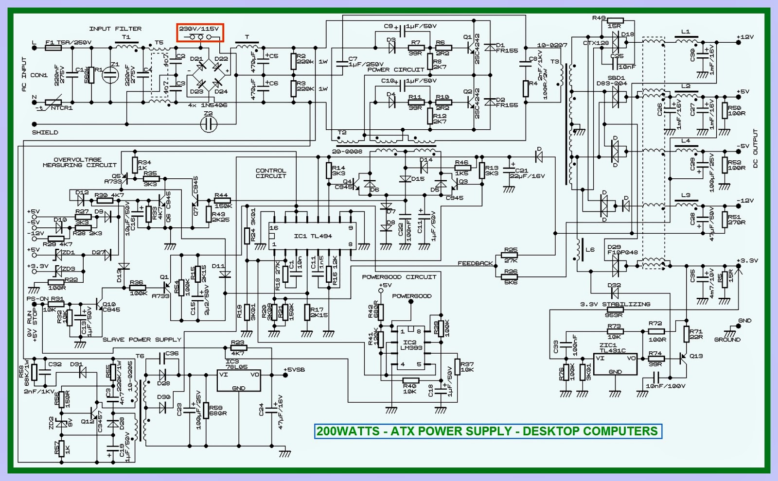
200W ATX power supply Circuit diagram & Output Voltages
SCHEMATIC
OUTPUTS

COLOR TV CIRCUIT DIAGRAM - 20 INCH

$
0
0
USED ICs - HEF4052 – 24C08 - TDA11105/TDA11106/TDA11126/TDA12135/TDA12136/TDA21296 – STV9302B/UTC74080 – BSC24-01N4006EV [FBT] – TDA7266SA/TDA7266MSA (Audio Output)
SCHEMATIC
CLICK ON THE SCHEMATIC TO MAGNIFY

KENSTAR - VIDEOCON-Slim - CTV CIRCUIT DIAGRAM

$
0
0
Videocon Slim CTV & Kenstar CTV schematic
Used ICs _ 24C32 (System Memory) – TDA12120H1/H [SMD (Stereo PAL-SECAM-NTSC)] – STV9302A (Vertical Scan output IC) – TDA7297 (Audio Output IC) - AN17821A – BSC24-1N4028T [FBT] – TDQ EWT-5F3T43-E27W [TUNER] – CQ0765RT [POWER SWITCHING]

SCHEMATIC
CLICK ON THE SCHEMATIC TO ZOOM IN


JBL 50.4 - CAR AMPLIFIER SCHEMATIC

$
0
0
JBL CS Series 50.4 _4 CHANNEL POWER AMPLIFIER - Circuit Diagram
SPECIFICATIONS
Output Power: 67W RMS x 4 channels @ 4 ohms; ≤1% THD + N
(14.4V supply) 82W RMS x 4 channels @ 2 ohms; ≤1% THD + N
162W RMS x 2 channels @ 4 ohms; ≤1% THD + N
Signal-to-noise ratio: 86dBA (reference 1W into 4 ohms)
Dynamic power: 145W @ 2 ohms
Effective damping factor: 6.395 @ 4 ohms
Frequency response: 10Hz – 27kHz (–3dB)
Maximum input signal: 6V
Maximum sensitivity: 240mV
Bass boost (45Hz) Variable 0 – 6dB
DC Offset <30mV
Output regulation: .032dB @ 4 ohms
Idle Current 0.65A
Input Impedance 20kΩ
Max Current Draw 26A @ 4 ohms
49A @ 2 ohms
Dimensions:
12 x 10 x 2 1/4”
(L x W x H)
(305mm x 254mm x 57mm)
Fuses: 25A x 2
  The CS subwoofer amplifier is a single-channel amplifier. There are two sets of terminals to make it easy to connect multiple woofers. Either set of (+/–) terminals may be used when connecting woofers.
SCHEMATICS
CLICK ON THE SCHEMATICS TO ZOOM IN

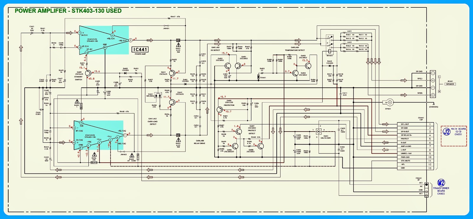
SONY - MHC-RG190 _ MHC-RG290 _ POWER AMPLIFIER & POWER SUPPLY SCHEMATIC

$
0
0
Power Supply & Power amplifier Circuit Diagram.
Sony MHC RG190 _ SONY MHC RG290 _ STK403-100 _  STK403-130 [Brazilian Model]
SCHEMATICS {Click on the schematics to Magnify}
See the next post here; to see the circuit diagram to main board_CD board & LD board

SONY HCD-RG190 _ HCD-RG290 - Brazilian Model _ CIRCUIT DIAGRAM - CD-BOARD - MAIN BOARD

$
0
0
HCD-RG190 _ HCD-RG290 - Brazilian Model - SONY DECK AMP - CD board - Main board - Tape deck board & Motor LD board _ Circuit Diagram.
Visit the previous post here to see the Amp & Power supply section circuit to this set.
Click on the pictures to magnify
CD BOARD
TAPE DECK BOARD
MOTOR LD BOARD
MAIN BOARD

STK --- SERIES - POWER-AMPLIFIER ICs and TYPICAL CIRCUIT DIAGRAMS

$
0
0
STK075G - STK077G - STK078G - STK080G - STK082G - STK083G - STK084G - STK085G - STK086G -- Power audio amplifier – typical circuit diagram
STK280-100 - STK280-130 Dual class-D power audio amplifier – typical circuit diagram
STK290-100 - STK290-130 Triple class-D power audio amplifier – typical circuit diagram
STK401-010 - STK401-020 - STK401-030 - STK401-040 - STK401-050 - STK401-060 - STK401-070 - STK401-080 - STK401-090 - STK401-100 - STK401-110 - STK401-120 - STK401-130 - STK401-140 - STK401-210 - STK401-220 - STK401-230 - STK401-240 - STK401-250 - STK401-260 - STK401-270 - STK401-280 - STK401-290 _ Dual power audio amplifier – typical circuit diagram

TYPICAL CIRCUIT DIAGRAMS - LM4668 – CXA1634M - BA4918-V12 and More

$
0
0
LM4668MH  _   BTL class-D power audio amplifier with shutdown.
1468 – 3571 – 3572 – 3573 – 8510 – 8515 – 8520 – 8530 - OPA502BM - OPA502SM - OPA511AM - OPA512BM - OPA512SM – OPA512SM – PA01 - PA10A - PA12 - PA12A - PA12H - PA12M - PA73 - PA73M - TPA12 - TPA12A _ Power operational _audio amplifier.
LM4668LD - LM4680SD _ BTL class-D power audio amplifier with shutdown.
5G31A - 5G31B - 5G31C _ Power audio amplifier.
A1034P - AN7108 - CXA1005P - CXA1034M - CXA1034P - CXA1634M - CXA1634P - KA22132 _ Dual playback preamplifier, volume control, power audio amplifier for headphone.
5G37 - Power audio amplifier.
BA4918-V12
WHAT IS SENSITIVITY
  Sensitivity of the amplifier understand value of the sine wave input voltage, necessary for obtain of the maximal output power. Frequently, some manufacturers indicate value of a nominal input voltage. A nominal input voltage is a sine wave voltage applied to an input of the amplifier for obtain of nominal output power. It is meant, that the volume regulator of the amplifier should be exposed on the maximal value.  Besides linear and nonlinear distortions, any real amplifier generates the additional signals. Because of it, on an output of the amplifier there is a signal distinct from zero, even in absence of an entrance signal. This signal called as output noise and can be considered as the sum of infinite number of sine wave voltage (not only harmonious) including in a sound range of frequencies. Sources of internal noise of the amplifier are thermal noise of resistors, and also shot, flickering and thermal noise of active components (transistors and diodes).   Quantitatively a value of noise on an output describe through effective value of noise. As the voltage of noise grows simultaneously with a range of reproduced frequencies, it is necessary to specify frequencies within the limits of which measurements of noise on an output of the amplifier were made. If the range of frequencies is not underlined, own noise are measured within the limits of a working range of frequencies of the amplifier.  The range of change of a output voltage is determined by a difference between the maximal and minimal instant value of a voltage on an output of the amplifier. These parameters called sometimes a peak output voltage and designate Up-p (peak-to-peak).
  There are many terms used to describe the amplifier power ratings- the maximal sinusoidal power, maximal continuous power, RMS power, music power (IHFM), peak power, instantaneous power. Depending on indicated term for output power, the same amplifier can have value which one differ in some times. Not resorting to the theories we shall mark that:
 Maximal sinusoidal power- is the power delivered on optimal load (for the given amplifier), at a sine-wave input signal, when THD of the output signal reaches value of 10%.
 Maximal continuous power- this same as maximal sinusoidal power and occurs under such name in the datasheets of USA and Japan manufacturers.
 RMS power- (Root Mean Square power). In the simplified form is described as the power, giving on optimal load (for the given amplifier), at a sine-wave input signal, when output signal completely limits by an output stage of the amplifier and gains the square shape.
 Musical power- IHFM (Institute of High Fidelity Manufactures) is the power delivered on optimal load (for the given amplifier), at a complex (musical) input signal, when THD of the output signal reaches value of 10%.  The peak power and instantaneous power describe extreme (critical) operation conditions of the amplifier and are specified basically in the advertising purposes.  
The impedance of load has optimal value for each amplifier and determines a maximum output current (power) giving by the amplifier. If the impedance of load is less than a optimal value, a output current (accordingly output power) of the amplifier can exceed maximum rating and he can be shattered. If the impedance of load is more than optimal value, the output current (accordingly output power) of the amplifier will be less (under identical conditions of operation) than is specified for the given amplifier.  On a connection type of load it is possible to distinguish single ended (SE) and Bridged-Tied Loads (BTL) amplifiers. On a single ended amplifiers the load are connected between an amplifier output and ground (GND).  Bridged amplifiers work basically as follows: a single input signal is applied to the amplifier. Internal to the amp, the input signal is split into two signals. One is identical to the original, and the second is inverted (sometimes called phase-flipped). The original signal is sent to one channel of the amp, and the inverted signal is applied to the second channel. Amplification of these two signals occurs just like for any other signal. The output results in two channels which are identical except one channel is the inverse of the other. The load is connected between the two amplifier output terminals. In words, one channel “pulls” one way while the second channel “pulls” in the opposite direction. This allows to deliver (at same load and at same power supply) in 3 times lot of power than at single ended amplifiers.  Due to improvements in the speed, power capacity and efficiency of modern semiconductor devices, the class-D amplifiers recently have received broad applying. Class-D amplifiers use a technique called pulse width modulation (sometimes combined with pulse frequency modulation). The input signal is converted to a sequence of pulses whose width at any time is proportional to the amplitude of the signal at that time. The frequency of the pulses is typically thirty or more times the highest frequency of interest in the input signal. The main advantages of a class- D amplifiers are efficiency and simplicity. Efficiencies are in the 80% to 90% range. Because the output pulses have a fixed amplitude, the switching elements (usually MOSFETs) are switched either on or off, rather than operated in linear mode. This means that very little power is dissipated by the transistors except during the very short interval between the on and off states. The wasted power is low because the instantaneous power dissipated in the transistor is the product of voltage and current, and one or the other is almost always close to zero.
WHAT IS INTER-MODULATION DISTORTION
  It is the second “major” type of distortion that is often specified for amplifiers.  Intermodulation distortion is much more objectionable to the human ear, because it generates non-harmonically related “extra” signals which were not present in the original. Basically, two pure tones are simultaneously applied to the input of the amplifier. If the amplifier were perfect, the two tones (and only the two tones) would be present at the amplifier output. In the real world, the amplifier would have some harmonic distortion (as described above), but careful observation of the output signal (using laboratory equipment) would reveal that there are a number of new tones present which cannot be accounted for as a result of harmonic distortion. These “new” tones are called “beat products” or “sum and difference” frequencies, and are a result of the interaction of the two pure tones within the amplifier.  No amplifier is perfect, all have some non linear characteristics. Whenever two signals are applied to a nonlinear system, new signals (in addition to the original two) are generated. For a good amplifier, the new signals are very small in relation to the two original tones.  All amplifiers are generally rated for Total Harmonic Distortion (or THD), usually at full power output over a given frequency band with a particular load. Good values are anything less than 0.5 %THD. When an amplifier is measured for THD, a pure tone is applied to the input and the output is measured with special test equipment. The energy of the pure tone is measured, and the energy of the harmonics is measured. Those two values are compared, and a THD rating is calculated. A THD rating of 1% means that the total energy of all the harmonics combined is one one-hundredth of the energy in the fundamental. Harmonic distortion (although certainly undesirable) is one of the more tolerable types of distortion as long as it is kept reasonably low. Distortion levels of 10% may be very tolerable.  At increase of input signal In the output voltage, a current and power are increased, but also the factor of nonlinear distortions simultaneously grows. Therefore, for reduction of nonlinear distortions target capacity of the amplifier are artificial limit in comparison with the greatest possible output power.

Viewing all 2033 articles
Browse latest View live


<script src="https://jsc.adskeeper.com/r/s/rssing.com.1596347.js" async> </script>