Quantcast
Channel: Electro help
Viewing all 2033 articles
Browse latest View live

TV POWER SUPPLY REGULATOR - SMPS - Circuits - USING REGULATOR ICs STR-KA5Q1265F – STR30110 – STR-F6626

0
0
STR-KA5Q1265RFSTR30110– Memorex MT2205 – STR-F6626– Memorex MT2235
SMPS SCHEMATICS
CLICK ON THE SCHEMATICS TO MAGNIFY


AIWA JAX-PK8 – AIWA CX-JT8 – Brazil – POWER OUTPUT and POWER SUPPLY SCHEMATIC

0
0
Front Speaker - Surround Speaker - Main Power Supply Circuit Diagrams and Exploded view of Speaker-box Aiwa JAX PK8 / CXJT8
SPEAKER BOX [EXPLODED]
POWER SUPPLY
AMPLIFIER CIRCUIT (Front & Surround)
Click on the pictures to Magnify

LG RAD125 – RAS125F – MINI HI-FI SYSTEM - SMPS and MAIN BOARD - SCHEMATIC

0
0
SMPS [Power Supply Regulator] & Main board Circuit Diagram _ LG RAD125 / LGRAS125F
ICs - TAS5342L – CS5346 – PS9850
SMPS SCHEMATIC  BOTTOM VIEW
SMPS SCHEMATIC
MAIN
CLICK ON THE PICTURES TO ZOOM IN

SAMSUNG UE32C4000P - LED TV - HOW TO UPGRADE SUB-MICOM WITH DDC MANAGER – USB DOWNLOAD METHOD

0
0
How to UPGRADE SUB-MICOM WITH DDC MANAGER – USB DOWNLOAD METHOD

SAMSUNG UE32C5*** - UE37C5*** - UE40C5*** - UE46C5*** - UE32C4000P* - LED TV

USB UPGRADE PROCEDURE
Samsung may offer upgrades for TV’s firmware in the future. Please contact the Samsung call center to receive information about downloading upgrades and using a USB drive. Upgrades will be possible by connecting a USB drive to the USB port located on your TV.

> Insert a USB drive containing the firmware (T-TDT5DEUC) upgrade into the USB port on the rear of the TV.
> Press the MENU button to display the menu.  Press the or button to select "Support", then press the ENTER button.
> Press the or button to select "SW Upgrade", then press the ENTER button.  The message "Scanning for USB. It may take up to 30 seconds." is displayed.
> The message "Upgrade version XXXX to version XXXX?  The system will be reset after upgrade." is displayed.
> Press the or to select the "OK", then press the ENTER button.

Be careful to not disconnect the power or remove the USB drive while upgrades are being applied. The TV will turn off and turn on automatically after completing the firmware upgrade.  Check the firmware version after the upgrades are complete. When software is upgraded, video and audio settings you have made will return to their default (factory) settings.
Write down your settings so that you can easily reset them after the upgrade.(Recommended)

HOW TO UPGRADE THE SUB-MICOM WITH DDC MANAGER
* Connect DDC MANAGER to the TV Set with D-SUB cable. And Power on.  (USB type : MTI-2510 / parallel type : MTI-2059)

* Enter the factory mode.  Control - EDID - EDID ON/OFF Select ON.
* Open the DDC tool. (Parallel type & USB type)

* Load the sub micom program fie (T-TDT5DEUS-XXXX.BIN).

* Push the ‘Program’ Button.  (It takes quite a bit of time. You can wait or close the DDC tool by force and open tool and load fie again.)

* Push the ‘Program’ Button again. (It takes about 100 seconds.)

If update completes, TV set will booting automatically. Disconnect the JIG.

> To enter the factory mode; press the remote control keys in this sequence [Power OFF > Info > Menu > Mute > Power On.]

If you want to enter the hidden factory mode.

# Enter into the factory mode first.

# Move the tap to Advanced

# Key in “0 + 0 + 0 + 0.  The hidden menu: Advanced will be displayed. Never enter factory mode and adjust the data values there, if you are not familiar with.  You should know, what you are going to do, and what will be the result.  Improper adjustments to data values here might make the set even in-operative; and irresponsive to any signal thereafter.


VIEWSONIC N-1800 LCD TV - SMPS (Power supply regulator) - SCHEMATIC

0
0
Power Supply Regulator Circuit Diagram _ Viewsonic  N1800TV(NT) - TEA1533AP
SCHEMATIC & PWB
CLICK ON THE PICTURES TO MAGNIFY

KONKA LCD TV - LC32AS28 – LC26A2 - ILO CIWL2606 and Funai 26 inch LCD TVs - SMPS SCHEMATIC

0
0
Used ICs - OZ9932 – 6930A – LD7575 – CE3B1065 – DLA001 – UCC28051 – STP10 (Power MOSFET) – PC123Y82 (Photo-coupler) - 2SK3797 Power Switching FET(ILO - Funai)
ILO-CIWL2606 and FUNAI 26 Inch LCD TV SMPS
CLICK ON THE PICTURES TO MAGNIFY

SAMSUNG 29 Inch CTV - CL29Z50MQTXXAO - CIRCUIT DIAGRAM

0
0
USED ICs & FBT - TDA7297-Audio Amp – LA78045-Vertical output – STR-X6750F-Power Switching – 24C161-EEPROM – VCT4822 or VCT49X3F-PY,F1,CT-2- Micom MTP IC – FUH29A001V FBT(LOT)
SYSTEM CONTROL SCHEMATIC
POWER AND DEFLECTION SCHEMATIC
CLICK ON THE SCHEMATICS TO ZOOM IN
UNIVERSAL REMOTE CONTROL SET-UP CODES TO CHECK WITH SAMSUNG BRAND TVs [for CRT_LCD & PLASMA types]
0030 0049 0050 0066 0076 0101 0102 0119 0143 0152 0154 0166 0181 0195 0209 0217 0240 0307 0318 0365 0379 0414 0421 0488 0492 0601 0624 0637 0642 0827


LG 55LA965V - LCD TV - SCREEN-SHOTS TO DEFECTIVE DISPLAY-Possible Faults

0
0
Screen-shots to Defective Display & Possible Causes _ Main board, Power Supply board and Display Module  _ LG55LA965V
North/Latin America_Europe/Africa_Asia/Oceania
MAIN BOARD FAULT SYMPTOMS
POWER SUPPLY BOARD FAULT SYMPTOMS
MODULE DEFECTS [These are non-repairable cases.  Exchange the Module is the only remedy]
THESE SYMPTOMS ARE COMMON TO MOST LCD TVs - IRRESPECTIVE OF ITS BRAND AND SCREEN SIZE.
CLICK ON THE PICTURES TO MAGNIFY

JVC LT-32C31 - WIDE LCD PANEL TELEVISION - HOW TO ENTER SERVICE MODE - MAIN POWER SUPPLY REGULATOR SCHEMATIC

0
0
JVC LT-32C31BJE, LT-32C31BUE, LT-32C31SJE, LT-32C31SUE - WIDE LCD PANEL TELEVISION
SERVICE MODE – MAIN POWER SUPPLY SCHEMATIC  [STR-F6268S-F3 Switching regulator]
Universal Remote control set-up code list for JVC brand TVs.

HOW TO ENTER SERVICE MODE
1. Press the [INFORMATION] key and the [MUTING] key of the REMOTE CONTROL UNIT simultaneously, and the SERVICE MENU screen will be displayed.
2. When the Main Menu is displayed, press any key of the [1] to [0] key to enter the corresponding menu mode.  *Press any of the [1] to [0] keys before the Service Menu mode disappears.
3. Select the service item using the [FUNCTION (UP / DN)] key.
4. Set the value using the [FUNCTION (LEFT / RIGHT)] key.
5. Press the [OK] key to save the value.

HOW TO EXIT THE SERVICE MODE
Press the [INFORMATION] key to exit the Service Menu mode.

SERVICE MODE MENU
MAIN POWER SUPPLY [Circuit Diagram]
PWB-SOLDER SIDE
Universal remote control set-up code list for JVC TVs
0007 0018 0075 0103 0123 0154 0163 0170 0182 0214 0225 0409 0433 0465 0657 0670

CLICK ON THE PICTURES TO MAGNIFY

AOC 193P - AOC193FW – POWER SUPPLY and BACK-LIGHT INVERTER SCHEMATICS

0
0
AOC -193P – AOC193FW –19 inch MONITOR - POWER SUPPLY and BACK-LIGHT INVERTER – CIRCUIT DIAGRAMS.
AOC 193P - AOC 193FW - POWER ADAPTERS - SCHEMATIC
AOC 193P & 193FW - BACK-LIGHT INVERTER
CLICK ON THE SCHEMATICS TO ZOOM IN

MICROLAB MICROLAB – X5II – MICROLAB X10II and MICROLAB AH200 STEREO AMPLIFIER – CIRCUIT DIAGRAM

0
0
USED ICs - LM1876 – PT2323 – TDA7448 – SG16C57 (Syscon)
AH200 - NE5532 – LM3886
SYSTEM CONTROL & DISPLAY SCHEMATIC
INPUT & TONE CONTROL SCHEMATIC
POWER SUPPLY & POWER AMPLIFIER SCHEMATIC
MICROLAB AH200 STEREO AMPLIFIER OUTPUT SECTION CIRCUIT
INPUT - PRE-AMP & POWER SUPPLY
CLICK ON THE SCHEMATICS TO MAGNIFY

TOSHIBA LE3256 - TOSHIBA DL3954 - LCD TV- SMPS - LED DRIVE - AMPLIFIER - SCHEMATIC

0
0
Toshiba  DL3244(A)W - DL3254(A)W - DL3954(A)F - DL3944(A)F - LE3256(C)W - LE4056(C)F
Used ICsOZ9902A (LED drive control) – FAN6755 (SMPS switching control) – 2N65 (Power switching MOSFET) – PC817B (Photo coupler) – STA33W (Audio Amplifier)
Universal remote control set-up codes
SMPS [POWER SUPPLY]
LED DRIVE
AUDIO AMPLIFIER
REMOTE CONTROL HANDSET SCHEMATIC
CLICK ON THE PICTURES TO ZOOM IN
Universal Remote control set-up codes to check with Toshiba Brand TVs
0018 0025 0039 0044 0045 0075 0101 0119 0128 0141 0143 0145 0165 0195 0227 0247 0369 0379 0460 0642 0658 0713 0810 0813 0814


PHILIPS FWT9200 – MINI Hi-Fi SYSTEM - SCHEMATIC DIAGRAM

0
0
FWT9200– MINI Hi-Fi SYSTEM - PHILIPS - TUNER - AMPLIFIER - CIRCUIT DIAGRAM - PCB LAYOUT - Used Output IC TDA8954TH
 

AM-FM TUNER
MAIN AMPLIFIER_LEFT & RIGHT
L-SUB_R-SUB_L-REAR_R-REAR
PCB LAYOUT

HOW TO ENTER SERVICE MODE TO NOBLEX 32LC815H - LCD TV

0
0
NOBLEX 32LC815H(Argentina) _ Service Mode _ main power supply (SMPS) circuit diagram - Used ICs FAN7602P – L6599DTRP

SERVICE MODE
* Press and hold the MENU button on Side Controls.
* Keep pressing the MENU button and press the MUTE button on the remote control, and the FACTORY MENU will be displayed.

* Select “DATA” line by pressing ▲/▼ button.

* Press◄► button to adjust data.


* Press MENU button to exit service mode.  The all adjusted data in service mode will be memorized into EEPROM automatically.

SMPS [Power supply] - schematic
PWB-SOLDER SIDE
CLICK ON THE PICTURES TO MAGNIFY

HOW TO ENTER SERVICE MODE - PANASONIC TC-P42X3 - PLASMA TV

0
0
Panasonic TC-P42X3 - 42 inch Class 720p Plasma HDTV - Service Mode _ LED blinking Codes
HOW TO ENTER THE SERVICE MODE
While pressing [VOLUME ( -- )] button of the main unit, press [INFO] button of the remote control three times within 2 seconds.

KEY COMMANDS
1> button...Main items Selection in forward direction
2 >  button...Main items Selection in reverse direction
3>  button...Sub items Selection in forward direction
4>  button...Sub items Selection in reverse direction
* [VOL] button: Value of sub items change in forward direction ( + ), in reverse direction (--)

TO EXIT THE SERVICE MODE
Switch off the power with the [POWER] button on the main unit or the [POWER] button on the remote control.

HOW TO ACCESS SELF CHECK
Prod Self-check indication and forced to factory shipment setting
* Produce TV reception screen, and while pressing [VOLUME ( - )] button on the main unit, press [MENU] button on the remote control for more than 3 seconds . 
* TV reception screen, and while pressing [VOLUME ( - )] button on the main unit, press [OK] button on the remote control for more than 3 seconds.

TO EXITDisconnect the AC cord from wall outlet.
Confirm the following parts if NG was displayed.

SCREEN DISPLAY & CHECK POINTS
POWER LED BLINKING
When an abnormality has occurred the unit, the protection circuit operates and reset to the stand by mode. At this time, the defective block can be identified by the number of blinks of the Power LED on the front panel of the unit.

BLINKING CODES
Local screen failure
Plasma display may have local area failure on the screen.

Click on the pictures to Magnify


FLUKE 192B _196B-C _199B-C Scope-Meter SCHEMATIC

0
0
ATTENTIONNever attempt to open this instrument, unless you’re familiar with repairing measuring instruments.  This is a very delicate and accurate measuring instrument. 
BATTERY
Battery operating time is does not meet the specification (4 hours)
1. Turn the ScopeMeter on (battery power only)
2. Check the voltage across R4101 (near the battery connector) for about 140 mV. This corresponds to a current of about 0.95 A. If the current is much higher the cause of the problem is not the battery.  

Battery is discharged when ScopeMeter is not used for some time (2 or 3 weeks).
1. Turn the ScopeMeter on (battery power only)
2. Check the voltage across R4101 (near the battery connector) for about 0.15 mV.  This corresponds to a current of about 1 mA. Turn the ScopeMeter off and on, and check the voltage again for 0.15 mV. Do this about 10 times.  If one or more times a current of about 1.2 mV is measured (8 mA), the cause is a defective IC D3550. This IC takes care of a correct power state of D3500.  As the 8 mA discharge current can have damaged the battery, you must check the battery capacity as described below.
3. If the current is much higher then 8 mA the cause of the problem is not or is not only D3550 
To check if the battery has a correct capacity
1. Do a battery refresh

2. Disconnect the BC190 Battery Charger/Power Adapter
3. Start a TrendPlot: RECORDER
4. When the battery is discharged the ScopeMeter will shut down. Now connect the BC190, turn the power on and check the length of the TrendPlot trace. For a new battery pack this should be about 4 hours. Depending on the number of applied charge cycles the battery capacity will decrease. If the TrendPlot trace has a length of 3 hours or less you may consider to replace the battery pack.

Loading Software
To load a new software version in the test tool contact an authorized Fluke Service center.

ELPLODED VIEW
FLY-BACK CONVERTER
1. Check the fly back converter output voltages +5V2, +3V3GAR (+3.3 V), +3V45, +2V6, -1V8, -5V2 and +30V.  Check FLTPOWIN1and FLTPOWIN2 (6.5Vrms, ≈ 70 kHz) on for example T1102 pin 3 and pin 5.

a.If one or more voltages are correct, then check the rectifier diodes, coils, and capacitors of the incorrect voltage (s)
b. If none of the voltages is correct, then the fly back converter does not run correctly, continue at step 2.
2. Check VBATT for >7 V.
3. Check N4000:49 (FLYGATE) for a square wave voltage of at least some volts (for a correct Fly Back Converter 50...100 kHz, ≅8 Vpp).  If no square wave is present on N4000:49 go to step 4.  If a square wave is present on pin 49 (maybe not the correct value), then check N4000:55 (FLYSENSP) for a saw tooth voltage of 50...100 kHz, 300 mVpp.

a. If no sawtooth voltage is present on N4000:55, no current or a DC current flows in FET V4001. The primary coil of T4001 or V4001 may be defective. Check also R4101 (current sense resistor); it can be fused due to a short in FET V4001.
b. An incorrect sawtooth on N4000:55 can be caused by:
* overloaded outputs (Frequency too low, <<50 kHz)
* underloaded outputs (Frequency too high, >>100 kHz)
* bad FET V4001 (Sawtooth voltage is not linear).
4. Check N4000:62 (PWRONOFF) for >+3V. If wrong, see Section 7.5.13 Power ON/OFF.
5. Check N4000:43 (COSC) for a triangle wave form, 50...100 kHz, +1.6 V to +3.2 V.  If wrong check C4123 and connections; check IREF, see step 6.
If all correct, then replace N4000.
6. Check N4000:74 (IREF) for 1.6 V. If wrong:
a. Check N4000:73 (REFPWM2) for +3V3. REFPWM2 is supplied by N4000, and derived from REFP. Check N4000:72 (REFP) for 1.22 V. If wrong, check V4114 and connected parts.
b. Check R4021, replace N4000.
7. Check N4000:51 (VOUTHI) for <2.5 V (nominal value 1.8 V). If wrong check R4014 and connections to N4000.
8. Check N4000:57 (IMAXFLY) for 570 mV. If wrong check R4020 and connections to N4000.

BACK-LIGHT
MAIN
CLICK ON THE PICTURES TO ZOOM IN

PANASONIC SC-AKX72LB-K CD Stereo System – SMPS and Power Amplifier Schematic

0
0
SC-AKX72LB-K CD Stereo System – SMPS and Power Amplifier Schematic _ PANASONIC

SMPS CIRCUIT DIAGRAM
POWER AMPLIFIER
CLICK ON THE SCHEMATICS TO MAGNIFY

LCD TV SMPS - SAMSUNG BN96-0B - SCHEMATIC (Circuit Diagram)

0
0
BN96_Samsung LCD Television SMPS - BACK-LIGHT INVERTER - Schematic
Used ICs _ TDA4863-SOPS – VIPER12ADIP – RS605M_600V6A – FQPF18N50V2 – F9222L – BCV62C
SCHEMATICS[CLICK ON THE SCHEMATICS TO ZOOM IN]

BN-7997 - INVERTER - SAMSUNG LCD TV - SCHEMATIC

0
0
Samsung LCD TV SMPS - BN-7997 - Circuit Diagram
Used ICs: SPA11N60 – Power Switching _ TDA4863 SOP8 _ VIPER22ADDIP _ MC33167 _ KIA278R12 _ F9222L-STR _ BCY62A
SCHEMATIC [CLICK ON THE SCHEMATICS TO MAGNIFY]

UN 55B7000WMXZD - SAMSUNG TFT- LCD TV - SERVICE MODE - TROUBLESHOOTING

0
0
How to enter Service Mode _ Samsung 55B7000WMXZD LCD TV _ Troubleshooting
SERVICE MODE
To enter ‘Service Mode’ Press the remote -control keys in this sequence:
If you do not have Factory remote – control.

MUTENumber Key(1)Number Key(8)Number Key(2)Power on

The buttons are active in the service mode.
1 Remote - Control Key : Power, Arrow Up, Arrow Down, Arrow Left Arrow Right, Menu, Enter, Number Key(0~9)
2 Function - Control Key : Power, CH +, CH -, VOL +, VOL -, Menu, TV/VIDEO(Enter)
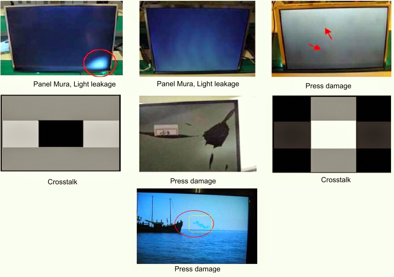
PANEL CHECK
You have to check Panel Maker Because of different adjustments as follows.
First of all, check the label rating

Label Rating File
LCD PANEL MARK
A:ACER(AUO) S : SEC C : CMO.  If not printed you could consider S(sec) panel mark.

WISE-LINK BUTTON
Using the WISELINK Function
This function enables you to view and listen to photo(JPEG), audio files(MP3) and movie(MPEG) saved on a USB Mass Storage Class (MSC) device.
* Press the POWER button on the remote control or front panel.
* The TV is powered on.
Connect a USB device containing JPEG and/or MP3 and or/MPEG files to the WISELINK jack (USB jack) on the side of the TV.
* (If you enter the WISELINK mode with no USB device connected the message “No external storage device found.  Check the connection status.” will appear. In this case, insert
the USB device, exit the screen by pressing the W.LINK button on the remote control and enter the WISELINK screen again.

> MTP (Media Transfer Protocol) is not supported.
> The file system only supports FAT16/32 (The NTFS fie system is not supported).
> Certain types of USB Digital camera and audio devices may not be compatible with this TV.
> Wiselink only supports USB Mass Storage Class devices (MSC). MSC is a Mass Storage Class Bulk-Only Transport device. Examples of MSC are Thumb drives and Flash Card
Readers (Both USB HDD and HUB are not supported.)
> connect directly to the USB port of your TV. If you are using a separate cable connection, there may be a USB Compatibility problem.
> Before connecting your device to the TV, please back up your files to prevent them from damage or loss of data. SAMSUNG is not responsible for any data fie damage or data loss.
> Do not disconnect the USB device while it is loading.
> MSC supports MP3 and JPEG files, while a PTP device supports JPEG files only.
> The sequential jpeg format is supported.
> Photo and audio files must be named in English, French or Spanish. If not, the files cannot be played. Change the file names to English, French or Spanish if necessary.
> The higher the resolution of the image, the longer it takes to display on the screen.
> The maximum supported JPEG resolution is 15360 x 8640 pixels.
> For unsupported or corrupted files, the “Not Supported File Format” message is displayed.
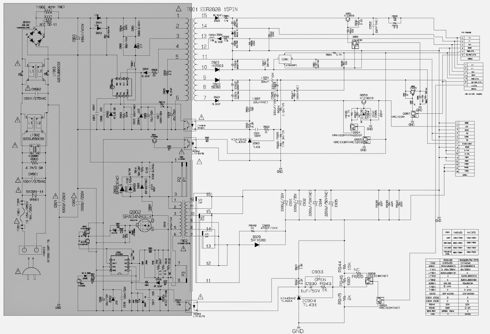
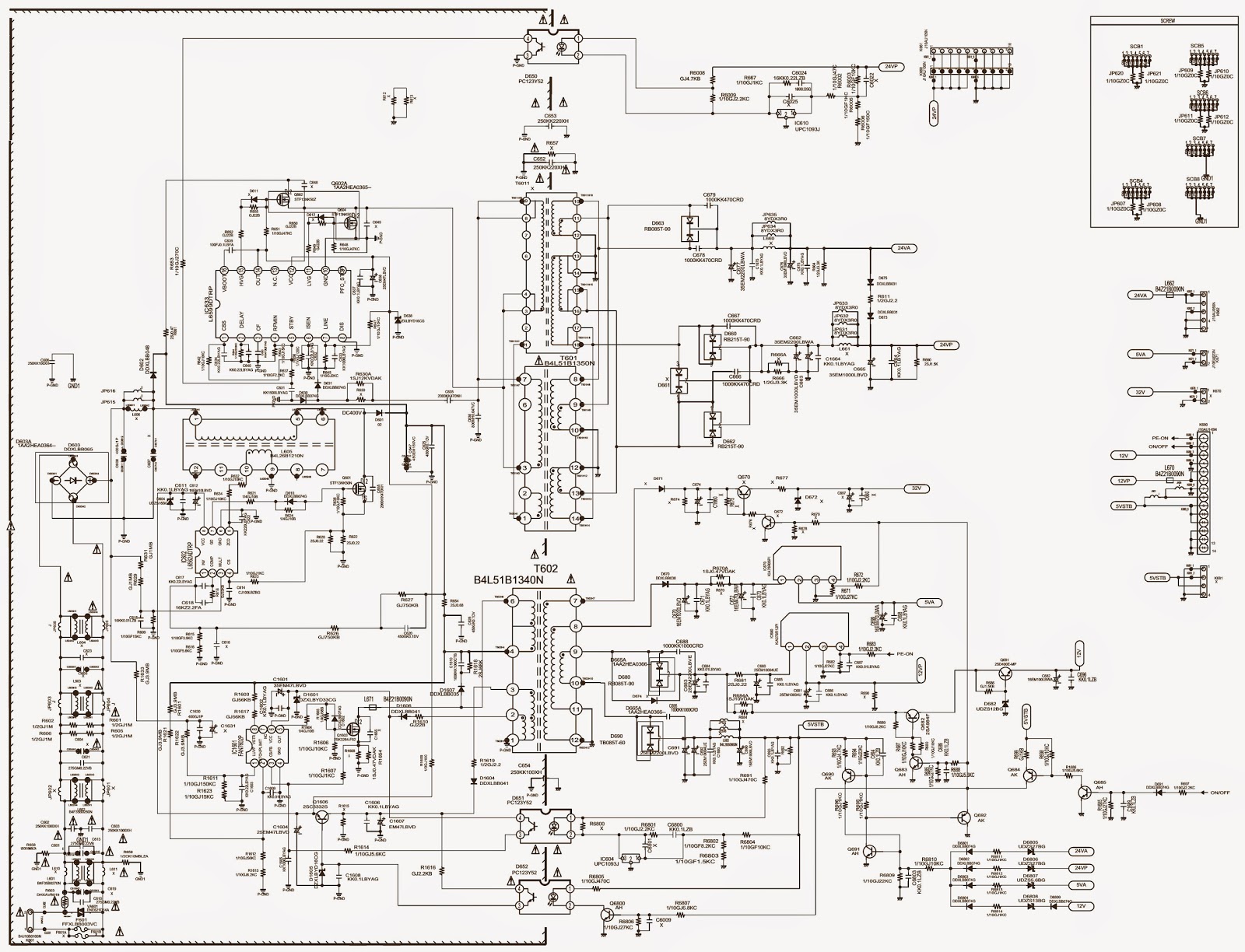
TROUBLESHOOTING
* Check the various cable connections fist.
* Check to see if there is a burnt or damaged cable.
* Check to see if there is a disconnected or loose cable connection.
Check to see if the cables are connected according to the connection diagram.  Check the power input to the Main Board.  Check the Power input to the FRC(Frame Rate Conversion) Board.  Check internal Pattern both of FRC and FBE3 if there is some picture noise.
FRC: Factory mode (MUTE - BUTTON 1 - BUTTON 8 - BUTTON 2 - Power on) > FRCM > TP After DDR Press right button of Remocon.
FBE3: Factory mode (MUTE - BUTTON 1 - BUTTON 8 - BUTTON 2 - Power on) > FBE > Patt Sel > Press right button of Remocon.
Case1: FBE3 ok, FRC NG: change the FRC Board Case2: FBE3 NG: change the main Board.
Check the LED lamp for source button on front.
If this LED blank 100mS frequently then FRC board is defective (communication problem via Main board) in this case change the FRC board.
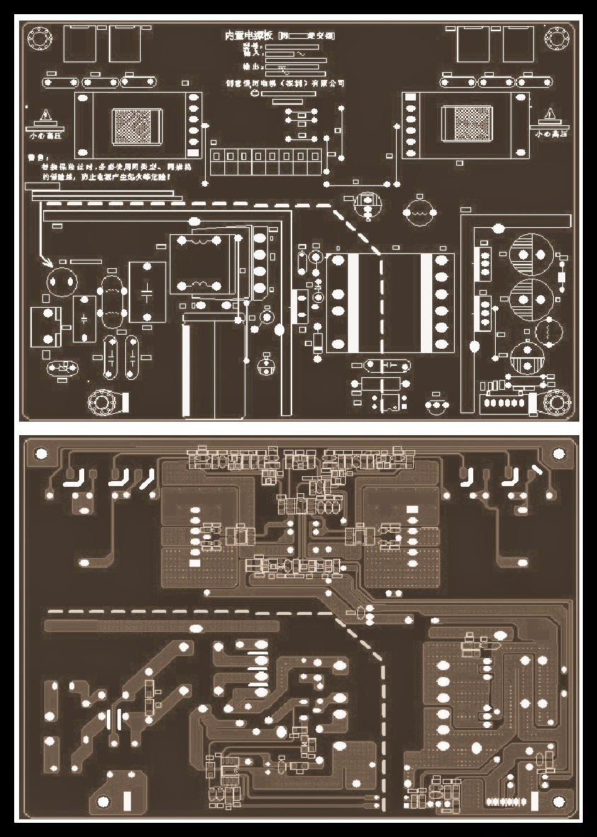
NO POWER
> The LEDs on the front panel do not work when connecting the power cord.
> The SMPS relay does not work when connecting the power cord.
The units appear to be dead.

The IP relay or the LEDs on the front panel does not work when connecting the power cord if the cables are improperly connected or the Main Board or SMPS is not functioning. In this case, check the following:
* Check the internal cable connection status inside the unit.
* Check the fuses of each part.
* Check the output voltage of SMPS.
Replace the Main Board.

NO VIDEO-Analog PC signal
Audio is normal but no picture is displayed on the screen.

> Check the PC source
> Check the SDP84 (ARSENAL)
This may happen when the LVDS cable connecting the Main Board and the Panel is disconnected.


Viewing all 2033 articles
Browse latest View live


Latest Images