Quantcast
Viewing all 2033 articles
Browse latest View live

HOW TO DISASSEMBLE SAMSUNG LE19C45*** - LE22C45*** - TFT-LCD TV

LE19C45*** - LE22C45***  Samsung TFT-LCD TV - Disassemble Procedure
DIS-ASSEMBLY
Place the TV face down on cushioned table.  Remove screws from the stand and back.
19 inch : 6 screws
22 inch : 8 screws.
Lift up the rear cover.
Remove screws and disconnect connectors.
19 inch : 6 screws
22 inch : 8 screws
Lift up the bracket and remove it.
Lift up the panel.
Reassembly procedures are in the reverse order of disassembly procedures.
Disconnect the LCD TV from the power source before disassembly.
Follow these directions carefully; never use metal instruments to pry apart the cabinet.
CLICK ON THE PICTURES TO MAGNIFY

UN46C9000ZF - SERVICE MODE – NETWORK PROBLEMS - SAMSUNG TFT LED TV

SAMSUNG UN46C9000ZF - UN55C9000ZF– TFT LED TV – SERVICE MODE – NETWORK PROBLEMS - Service Mode _ EDID sucess Mode
SERVICE MODE
How to Access Service Mode
Using the Customer Remote
1 Turn the power off and set to stand-by mode
2 Press the remote buttons in this order; MUTE-1-8-2-POWER ON to turn the set on.
3 The set turns on and enters service mode. This may take approximately 20 seconds.
4 Press the Power button to exit and store data in memory.  - If you fail to enter service mode, repeat steps 1 and 2 above.
Initial SERVICE MODE DISPLAY State  (If you entered Service Mode by Customer Remote , 'Expert' and 'Advanced' menu would be hidden for security)
"Advanced" is hidden menu.
You can not enter "Advanced" mode even you entered Service Mode using Factory Remote.
Buttons operations within Service Mode
Direction Keys [Up / Dn] > Item Selection by Moving the Cursor
Direction Keys [Left / Right] > Data Increase / Decrease for the Selected Item
Source > Cycles through the active input source that are connected to the unit
How to Access ‘EDID SUCCESS’ Mode
At initial SERVICE MODE DISPLAY state, you’ll see ‘EDID SUCCESS’.  If not, go to
Control > EDID and follow the procedure.

1. Set ON at EDID ON/OFF menu.
2. at EDID WRITE ALL menu, press the Right Arrow key of the remote control. After few seconds Success will appear.
3. If Failure appears, remove the PC cable and HDMI cable that connected to TV. And try it again.
4. If the problem still exists, go to HDMI EDID Ver menu, and change the HDMI version to HDMI 1.2 or HDMI 1.3.
5. Change the Main Board if same problem occurs.
HOW TO SET-UP NETWORK
Click the [Menu] button and open [Setup] to select [Network].  Confiure wired or wireless network settings.
How to check the network status
Select [Menu] >[Setup] >  [Network] and run [Network Test] to see test results and check the network status.
In a network test over a wired connection, the second items which include the IP address, subnet, gateway and DNS server fail.
If the IP address, subnet mask and gateway address were typed in manually, check that valid values were entered.  (For example, 0.0.0.0 is not valid for an IP address, subnet mask or gateway address.)
If the IP address the user entered in is invalid, change it to a valid IP address.
In a network test over a wired connection, the third item, gateway ping fails.
1. Check that the network cable is connected to the TV correctly.
2. If the TV is connected correctly, check whether the IP address is automatic or manual.
3. If the IP is automatic and connected to a sharing device, check the settings of the sharing device (AP) that is using a cable connection, or consult the corresponding Internet service provider.
4. If the IP is manual, check if the IP address is entered correctly. (Here, the user should confirm if the manual IP address entered in is valid.)
Cannot connect to a wireless network.
1. If an encryption key must be entered in to connect to a sharing device, please check that the correct password set for the sharing device is entered.
2. Search surrounding sharing devices to see if there is a sharing device with the same SSID by selecting [Wireless Network Setup] and [Select Network].  If there is a sharing device with the same SSID, try to connect to this device.
3. If the IP address is set to automatic and you cannot connect to the sharing device using option 1 or 2, check the settings of the sharing device to see if the DHCP server function on the sharing device is enabled. If disabled, activate the function. (For details on how to set up the sharing device, see the manual for the corresponding sharing device.)
4. If you still cannot connect to the sharing device after confirming options 1, 2 and 3, reset the sharing device and try again.
When using a wireless network, the user’s wireless sharing device cannot connect to the PBC (WPS)
Check if the sharing device of the user supports WPS.
2. Check if the user pressed the PBC button on the sharing device.
3. If there is another sharing device with WPS running nearby, a connection cannot be made. Please retry after 2 minutes.
4. Reset the sharing device and retry.
5. If the sharing device of the user is not Wi-Fi certified, it may not be able to connect using WPS.
The auto-configuring sharing device cannot be connected to automatically through a wireless dongle.  (Here, the user’s sharing device must support auto-configuration.)
1. Check if the sharing device of the user supports auto configuration.
2. If the sharing device of the user supports auto configuration, place the sharing device as close as possible to the wireless dongle on the TV and try to re-establish the connection. (Must be placed close to the TV to establish a connection.)
Cannot connect to a wireless network (2) or AP
* There could be several causes of the connection failure. Check the AP settings to see if the following condition is found.
* The Pure high-Throughput 802.11n mode (or Greenfield 802.11n mode) is selected and the Encryption type is set to WEP, TKIP or TKIP-AES. • Under the conditions stated above, Samsung TVs will not support a connection in compliance with new Wi-Fi certification specifications. This is intended to maximize the performance of the AP, TV and TV network.  To connect to the AP, set the Encryption type to AES. If Pure High-Throughput 802.11n mode (or Greenfield 802.11n mode) is selected and the Encryption type is set to AES, your Samsung TV will connect to the AP providing you with optimum
performance.
Although the TV is placed close to the AP and the dongle is inserted into the TV, the sharing device cannot be connected to using auto-configuration.
Select [Menu] > [Setup] > [Network] and check if SWL is Off.
If the AP is turned off, the TV will try to re-establish a connection for 2 minutes.
Although the TV is placed close to the AP and the dongle is inserted into the TV, the sharing device cannot be connected to using auto-configuration and a message that it is connecting is displayed only
Check if the AP is not turned off during connection.  If the AP is turned off, the TV will try to re-establish a connection for 2 minutes.
In order to use the Samsung Auto Configuration function, I did as the user manual instructed. I get a message that connecting to an external network has failed
The Samsung Auto Configuration feature is designed to establish an auto connection between the TV and the gateway of the AP. It performs a connection test if the AP is connected to an external network.
If the AP is not connected to an external network, a message that establishing a connection to an external network has failed is displayed. In this case, connect the AP to an external network. After a connection to the external network is established through a network test, you can use the network without any problem. Check if the AP is connected to an external network.  If you perform a test when a connection to an external network is established through a LAN cable, you will obtain successful test results.
When SWL is On,  cannot connect to the 5GHz Wi-Fi mobile device
SWL is connected to a Wi-Fi mobile device which uses 2.4GHz bandwidth and supports PBC (Push Button Configuration) mode.  A mobile device which uses 5GHz or 2.4GHz bandwidth but does not support PBC cannot be connected to the TV.
* WPS: WPS is the acronym for Wi-Fi Protected Setup, and includes two types: PBC (Push Button Configuration) type which performs cross certification with the press of a button and PIN type which performs cross certification when a PIN (Personal Identification Number) code is entered.
Although the TV is placed close to the AP and the dongle is inserted into the TV, the sharing device cannot be connected to using auto-configuration and a message that it is connecting is displayed only.
* If Samsung Wireless Link is On, a 5G-bandwidth wireless sharing device may not be found in a search (restriction).
* If Samsung Wireless Link is Off or the product does not have the Samsung Wireless Link function, please retry searching to fid the sharing device. (May not be found in a search depending on the settings of the wireless connection.)
In a network test over a wireless connection, the second items which include the IP address, subnet, gateway and DNS server fail
*If the IP address, subnet mask and gateway were typed in manually, check that valid values were entered. (For example, 0.0.0.0 is not valid for an IP address, subnet mask or gateway address.)
* If the IP address the user entered in is invalid, change it to a valid IP address.
In a network test over a wireless connection, the third item, gateway ping fails.
1. If the IP address is automatic and connected to a sharing device, check the settings of the sharing device (AP) that is using a cable connection, or consult the corresponding Internet service provider.
2. If the IP address is manual, check that the IP address is entered in correctly. (Here, the user should confirm if the manual IP entered in is valid.)
In a network test over a wireless connection, the fourth item, Internet service test fails.
Consult the corresponding Internet service provider (an Internet network service provider the user has subscribed to such as KT)
InfoLink
To select another song in the slideshow
Only the default song provided in the widget is available.
The "Recent Photos" change continuously.
The corresponding information is received from the CP and is irrelevant to your TV.  The "Recent Photos" are updated in real time.
The same news articles are always shown. (The list of articles is not updated.)
After an account and logged into the system, when  enter My Apps or My Cyber Cash on My Page, the message "Your login account has a problem." is displayed.
This occurs because you are not connected to your partner account for Samsung
Apps. Connect to your partner account on the Settings page using your actual PC website account and then try again.
The Goods List icons disappear temporarily
Since the goods information including the icons is downloaded via the Internet to be displayed on the screen, they may be shown with a delay depending on your network status.
When  select this operation and press "Enter" on the remote control,  not moved to the proper page and a detailed advert page is displayed.
To use the Internet @TV normally, you must connect to the Internet and agree to the User License Agreement.
How many cities can I add to My Interest Cities?
Can add up to 20 cities.
Cannot fid the city for which  want to view weather.
Select [Menu] >[Setup] >[Network] and check if SWL is Off.
How frequently is weather information updated
Weather information is real-time information but there may be a slight time difference. If the Widget is run continually, the weather information is updated every 30 minutes.
No traffic information is shown
Traffic information for countries and areas is limited. As of December 2009, traffic information is only provided for the USA, England, France, and China (some big cities).
What are the differences between the map types?
MAP: Normal street map. Satellite: Satellite photo. Hybrid: Satellite photo + street map.
No map is displayed.
1. Check whether the map is magnified too much.  Try to change to a middle zoom ratio.
2. There may be no map data for a location in an ocean.  Try to use the Search function to search the map using a location name.
3. Connect to the Google Maps website (http://maps.google.com) and check whether the Google Maps server is operating normally
What is the difference between when the widget after logging in and when  use the widget without logging in
When you enter the widget after logging in, you can save the video you are watching in the storage space assigned to your login account. You can also view the videos added as your favorites from the Favo rites category or from the favorites of your YouTube site account
What is the difference between when  use the widget after logging in and when I use the widget without logging in?
When you enter the widget after logging in, you can zzim (select) the video you are watching and save it in the storage assigned to your login account. From the My Zzim category, you can also view the videos you zzimed (selected) on the KBS zzim website (http://www.kbs.co.kr/zzim/section/) or your TV.
How many videos can save on the TV Box
Can save up to 40 videos
Where can  create  login ID and charge my cyber money
You can create your ID and charge your SBS cyber money account on the SBS website.
Cannot log into Twitter.
To use Twitter, you must log in to it fist.
Create your account on the Settings page, register your created account on the Twitter website (www.twitter.com), and then log in to Twitter using your registered ID. If you cannot access Twitter after you have logged in, it may be a temporary service error. Try again after a while.
Logged into the system with a different user account. But the interests do not change.
It is not supported to have different interests for each login user.  You can set up to 20 interests.
The current time does not change
The current time is designed to be updated every hour
How to view the weather after a week
The weather information is only provided for a week from today.

FUNAI - 32FL553P-10 32FL553-10 - LED-LCD TV - SERVICE MODE – INITILIZE – Firmware Update

How to enter Service Mode _ Initialize _ Firmware Update _ FUNAI 32FL553P-10 -  32FL553-10 _ 32˝ COLOR LED-LCD TELEVISION
SMPS (Main Power Regulator_ Schematic Diagram_PWB 
Used ICs Power Regulator Circuit: FA8A00N [Switching Control] _ TK5A65D [Switching MOSFET] x 2 _ TLP781F [Photo-coupler] _ MP2482DN-C447-LF-Z [+5V Regulator] _ FDD5612 [STB + 5V & for +13V Switching] _ HA7219PB [LED Back-light Driver]
Universal Remote Control Set-up Codes to check with FUNAI brand TVs [all types] - With Different brand remote controls
HOW TO ENTER SERVICE MODE
1. Turn the power on.
2. Press [SOURCE], [2], [5], [8] and [0] buttons on the remote control unit in this order to enter the service mode.
The Factory Setting menu appears in the screen.
HOW TO INITIALIZE
Turn the power on.
2. Enter the service mode.
> To cancel the service mode, press [BACK] button on the remote control unit.
3. Select “Factory Reset” and [OK] button on the remote control unit.  The TV set will go off and turn back on automatically when initialization completes.
HOW TO UPDATE THE FIRMWARE
1. Prepare USB storage device.
2. Copy F/W-file to USB storage device.  Note: Make sure to use the blank USB Storage.
3. Make sure that the F/W-file’s name is “LC11_308B_FUNAI.bin
Update procedure
1. Turn the power on.
2. Insert USB storage device with F/W to TV set.
3. Press the [MENU] button on the remote control unit to display Menu.
4. Select “SETUP”.
5. Select “Software Update (USB)” and press [OK] button.  
The message “Are you sure?” will appear in the screen.
6. Press [LEFT] button to select “YES”.
7. Updating starts.  Note: Do not turn off the TV set and do not remove the USB storage device while this procedure.
8. The TV set will go off and turn back on automatically when update completes.
Additional step:
A1. Enter the service mode.
A2. Select "Init TV" and press [OK] button.  The TV set will go off and go back on automatically.
A3. Adjust the white balance.
White Balance Adjustment
Purpose: To mix red and blue beams correctly for pure white.
Symptom of Maladjustment: White becomes bluish or reddish.
1. Operate the unit for more than 60 minutes.
2. Input the White Raster of composite video signal to AV (70%=70IRE, 40%=40IRE).
3. Enter the service mode.
4. Press [0] button on the remote control unit to display the “White Balance” menu.
Additional step:
A1. Press [2] button on the remote control unit to select the “Colour Temp” menu.
A2. Press [] or [] button to select the "Normal".
5. Select a color mode (“3 R-GAIN”, “5 B-GAIN”, “6 R-OFFSET” or “8 B-OFFSET”).
6. Set the color analyzer at the CHROMA mode and zero point calibration. Bring the optical receptor pointing at the center of the LCD-Panel.  Note: The optical receptor must be set perpendicularly to the LCD Panel surface.
7. In each color mode, press [ s] or [ B] button to adjust the color temperature becomes 12000°K (x= 0.272 / y= 0.278 ±0.002).
8. To cancel or to exit from the White Balance Adjustment, press [BACK] button.
SMPS CIRCUIT DIAGRAM
PWB - TOP & BOTTOM VIEW
  Because a hot chassis ground is present in the power supply circuit, an isolation transformer must be used when repairing.  Also, in order to have the ability to increase the input slowly, when troubleshooting this type of power supply circuit, a variable isolation transformer is required.
  Fixed voltage (or Auto voltage selectable) power supply circuit issued in this unit. If Main Fuse (F602) is blown, check to see that all components in the power supply circuit are not defective before you connect the AC plug to the AC power supply.  Otherwise it may cause some components in the power supply circuit to fail.
  For continued protection against fire hazard, replace only with the same type fuse.
UNIVERSAL REMOTE CONTROL SET-UP CODES
0042 0076 0094 0601 0616 0654
If your TV asks for a 3 digit code; just strike out the leading 'Zero' of each code; and check with it.
For example, if the four digit code is 0601; you can make it as '601' (3-digit code) by deleting the leading zero.  Like-ways; you can check  all the other codes stated here..
CLICK ON THE PICTURES TO MAGNIFY

LCD 42XF6 (Argentina) - SANYO - HOW TO ENTER SERVICE MODE - INITIAL DATA SETTING

SANYO 42XF6 (Argentina)_Service Mode _ Main Power Regulator [SMPS] Circuit Diagram [Schematic]
Used ICs - 6599DTRP – L6562ADTRP – FAN7602P – 2SK3264 [FET] – PC123Y-52  [Photo-coupler]
Universal remote control set-up codes to Sanyo Brand TVs; with different brand Remote Controls (Sorted)
SERVICE MODE
1.Press and hold the MENU button on Side Controls.
2. Keep pressing the MENU button and press the MUTE button on the remote control, and the FACTORY MENU will be displayed.
* Select “DATA” line by pressing ▲▼ button.  Press ◄►button to adjust data.
* To exit service mode Press MENU button to exit service mode.   The all adjusted data in service mode will be memorized into EEPROM automatically.
INITIAL DATA SETTING
This adjustment is controlled by the CPU (IC8000) through the IIC Bus Data Line in the chassis, and those adjustment data are memorized the memory IC (IC8001). Therefore, Main board or the memory IC (IC8001) is replaced, these data will be disappeared. Readjust should be made. Initial data is provided in the CPU ROM, when the memory IC (IC8001) is replaced with new one. CPU ROM data is loaded into the memory. Initial data is provided to operating the
monitor basically. For operating the monitor quality performance, further adjustment is required following chassis electrical adjustment.
1.Receive good quality signal.
2.Enter the Service Mode.
3.Confirm data value to be the same as the Service Adjustment Data Table. If it is different, change to correct data
4. Exit the Service Mode.
SMPS SCHEMATIC _ COMPONENT & SOLDER SIDE VIEWS
Universal remote control set-up codes
0018 0020 0041 0049 0050 0065 0101 0102 0107 0131 0139 0152 0161 0166 0177 0181 0195 0198 0209 0215 0314 0320 0379 0391 0408 0421 0634 0660 0667
CLICK ON THE PICTURES TO ZOOM IN

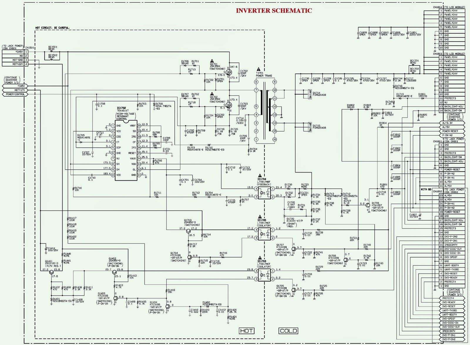
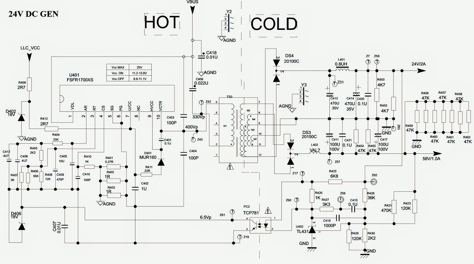
SAMSUNG BN96-0-1 and PHILIPS 42PFL3704D – SMPS - INVERTER SCHEMATICS

Power Supply Regulators - Samsung BN96& Philips 47PFL3704D - Circuit Diagrams.
Used ICs: UCC28060DR [Power control] _ 2SK3561 [power switching] – TEA1611T [High voltage resonant control] – MC33167 – FS7M0880 – VIPER12A – LM2576
SAMSUNG BN96 - SCHEMATIC
PHILIPS 42PFL3704D - SMPS & INVERTER SCHEMATICS
CLICK ON THE SCHEMATICS TO MAGNIFY

SONY KV32HS – KV42DRC - SERVICE MODE – SELF DIAGNOSIS – HORIZONTAL SCAN and SMPS SCHEMATICS

Self Diagnosis Function _ Service Mode_LED blinking codes _ Horizontal & Main Power Regulator [SMPS] Circuit diagram.
Applicable to Sony ModelsKV-32HS500 RM-Y186 CND SCC-S70A-A /  KV-32HV600 RM-Y187 US SCC-S66B-A  /  KV-34DRC500 RM-Y186 LATIN NORTH SCC-S71A-A  /  KV-34DRC500 RM-Y186 LATIN SOUTH SCC-S71B-A  /  KV-34XBR800 RM-Y188 US SCC-S66F-A  /  KV-34XBR800 RM-Y188 CND SCC-S70D-A  /  KV-36HS500 RM-Y186 US SCC-S66C-A  / KV-36HS500 RM-Y186 CND SCC-S70B-A  /  KV-36HS500 RM-Y186 HAWAII SCC-S69B-A / KV-36XBR800 RM-Y187 US SCC-S66D-A /  KV-36XBR800 RM-Y187 CND SCC-S70C-A /  KV-36XBR800 RM-Y187 HAWAII SCC-S69C-A  / KV-38DRC500 RM-Y186 LATIN NORTH SCC-S71C-A  / KV-38DRC500 RM-Y186 LATIN SOUTH SCC-S71D-A  / KV-40XBR800 RM-Y187 US SCC-S66E-A  /  KV-40XBR800 RM-Y187 CND SCC-S70E-A  /  KV-40XBR800 RM-Y187 HAWAII SCC-S69A-A  / KV-42DRC800 RM-Y187 LATIN NORTH SCC-S71E-A
SELF DIAGNOSIS
  The units in this manual contain a self-diagnostic function. If an error occurs, the STANDBY/TIMER LED will automatically begin to fl ash. The number of times the LED fl ashes translates to a probable source of the problem. A definition of the STANDBY/TIMER LED fl ash indicators is listed in the instruction manual for the user’s knowledge and reference. If an error symptom cannot be reproduced, the Remote Commander can be used to review the failure occurrence data stored in memory to reveal past problems and how often these problems occur.
  When an error occurs, the STANDBY/TIMER LED will flash a set number of times to indicate the possible cause of the problem. If there is more than one error, the LED will identify the first of the problem areas.  Results for all of the following diagnostic items are displayed on screen. If the screen displays a “0”, an error has occurred.
* If a +B over-current is detected, stoppage of the vertical deflection is detected simultaneously. The symptom that is diagnosed first by the micro-controller is displayed on the screen.
** Check the screen (G2) voltage for abnormality in this case.
*** If STANDBY/STEREO LED flashes six (6) times, unplug the unit and wait 10 seconds before performing the adjustment.
Stopping the Standby/Timer LED Flash
Turn off the power switch on the TV main unit or unplug the power cord from the outlet to stop the STANDBY/TIMER LAMP from flashing.
Self-Diagnostic Screen Display
For errors with symptoms such as “power sometimes shuts off” or “screen sometimes goes out” that cannot be confirmed, it is possible to bring up past occurrences of failure on the screen for confirmation. 
To Bring Up Screen Test
In standby mode, press buttons on the Remote Commander sequentially, in rapid succession.
DISPLAY> Channel [5]Sound volume (--)> Power ON.
Handling of Self-Diagnostic Screen Display
Since the diagnostic results displayed on the screen are not automatically cleared, always check the self-diagnostic screen during repairs. When you have completed the repairs, clear the result display to “0”.  Unless the result display is cleared to “0”, the self-diagnostic function will not be able to detect subsequent faults after completion of the repairs.
Clearing the Result Display
To clear the result display to “0”, press buttons on the Remote Commander sequentially when the diagnostic screen is displayed, as shown below:
Channel 8ENTER
Quitting the Self-Diagnostic Screen
To quit the entire self-diagnostic screen, turn off the power switch on the Remote Commander or the main unit.
Self-Diagnostic Circuit
+B over-current (OCP)
Occurs when excessive current fl ows through R5013. The increase in voltage across R5013 causes the output of Q5004 to go high, and this high signal goes to the micro.
+B over-voltage (OVP)
IC6505 detects +B OVP condition and turns on Q6522. This sends a high signal to the micro and also shuts down the AC relay.
V-STOP
Occurs when an absence of the vertical de fl ection pulse is detected by pin 24 of IC2801 (B Board). Power supply will shut down when waveform interval exceeds 2 seconds.
White Balance Failure
If the RGB levels* do not balance within 2 seconds after the power is turned on, this error will be detected by IC2801. TV will stay on, but there will be no picture.
*(Refers to the RGB levels of the AKB detection Ref pulse that detects 1K).
Low B OCP/OVP
1. Occurs when set 5V is out.
2. Horizontal Deflection Stopped
3. Occurs when either:
1) a +B over current is detected (IC5007), or
2)
overheating is detected (Thermistor TH5002).
SERVICE ADJUSTMENT MODE
1. Standby mode (Power off).
2. Press the following buttons on the remote commander within a second of each other:
DISPLAY >  Channel 5 >  Sound Volume
[+]>  Power.

3. The CRT displays the item being adjusted.
4. Press 1 or 2 on the Remote Commander to select the item.
5. Press 3 or 6 on the Remote Commander to change the data.
6. Press MUTING then ENTER to write into memory.
SERVICE ADJUSTMENT MODE MEMORY
7. Press then on the Remote Commander to initialize.
8.DO NOT turn off set until SERVICE appears.
READING THE MEMORY
1. Enter into Service Mode.
2. Press 0 on the Remote Commander.
3. Press ENTER to read memory.
ADJUSTING THE PICTURE
1. Enter into Service Mode
2. Press 2 or 5 on the remote to select the device item.
3. Press 1 or 4 on the remote to select an item.
4. Press 3 or 6 on the remote to change the data.
5. Press MUTING then ENTER to write into memory.
RESETTING THE DATA
Note:
Be careful when using the remote! It will clear and re-initialize ALL NVM data including deflection adjustment data if not reset properly as follows:
RESETTING THE MID NVM DATA
1. Enter into Service Mode.
2. Press 7 , then JUMP , and then press ENTER on the remote.
RESETTING THE SYSTEM NVM DATA
1. Enter into Service Mode.
2. Press
7 , then 9 , and then press ENTER on the remote.
COPY FUNCTION
How to use copy function for DA4 Chassis
• After writing your adjusted data into NVM MUTING then ENTER , copy can be made by changing copy data from 0 to 1 then MUTING , ENTER again.
WARNING: DO NOT copy data before writing your corrected data in NVM. If data is copied before writing corrected data, old data will be copied.
• CPY1: DF/DQP DATA
• CPY2: CONVERGENCE DATA 
MEMORY WRITE CONFIRMATION METHOD
1. After adjustment, pull out the plug from the AC outlet, then replace the plug in the AC outlet again.
2. Turn the power switch ON and set to Service Mode.
3. Call the adjusted items again to confirm they were adjusted.
SMPS SCHEMATIC
DEFLECTION SCHEMATICS
CLICK ON THE PICTURES TO MAGNIFY

LG 42LG80FR – LCD TV - FIRMWARE UPGRADE – EDID DATA DOWNLOAD

42LG80FR – FIRMWARE UPGRADE – EDID DATA DOWNLOAD - Power Amplifier & Sub-Woofer Amplifier Schematic [Circuit Diagram] - LG LCD TV
Used ICs: NTP3000A – LM324 – MC74HC4066ADR2G
Universal remote control set-up codes with (different brand universal remote controls) to check with LG Brand TVs [All types]
MAIN SOFTWARE DOWNLOAD PROGRAM PROCEDURE
1 Download method 1 (PCB Assy) – HD
2 Connect the download jig to D-sub jack
3 Execute ‘ISP Tool’ program in PC, then a main window will be opened.
4 Click the connect button and confirm “Dialog Box”.
5 Click the Config button and Change speed E2PROM Device setting : over the 350Khz.
6 Read and write bin file: Click “(1) Read” tab, and then load download file(XXXX.bin) by 7 clicking “Read”.
7 Click “Auto(2)” tab and set as below
8  click “Run(3)”.
9 After downloading, check “OK (4)” message.
EDID (The Extended Display Identification Data) /DDC (Display Data Channel) download
Caution:Use the proper signal cable for EDID Download.
Never connect HDMI & D-SUB Cable at the same time.
Use the proper cables below for EDID Writing.
EDID DATA
HDCP SETTING (High-Bandwidth Digital Contents Protection)
1 Connect D-sub Signal Cable to D-Sub Jack
2 Input HDCP key with HDCP-key- in-program
3 HDCP Key value is stored on EEPROM(AT24C64) which is From “0x80” addresses.
4 AC off/ on and on HDCP button of MSPG925 and confirm whether picture is displayed or not of using MSPG925
5 HDCP Key value is different among the sets.
# Before HDCP Download, you have to set the Configuration that CMD delay. > Configuration > Option > I2C(16 Byte Write : 20ms, 128 Byte Read : 20ms, Read CMD Byte : 0.5ms, I2C Clock : 45KHz.
MAIN AMPLIFIER & SUB-WOOFER AMPLIFIER SCHEMATIC
URC SET-UP CODE LIST LG (GOLDSTAR)
0011 0025 0049 0050 0054 0055 0101 0107 0110 0119 0152 0165 0166 0168 0181 0182 0195 0235 0250 0303 0379 0380 0414 0421 0433 0460 0465 0611 0613 0658
CLICK ON THE PICTURES TO ZOOM IN

PHILIPS - PHILCO - PH39E53SG – LED LCD TV – CIRCUIT DIAGRAM


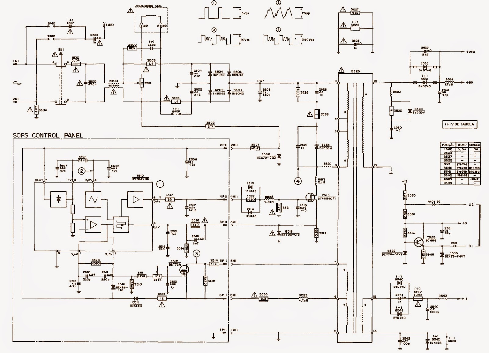
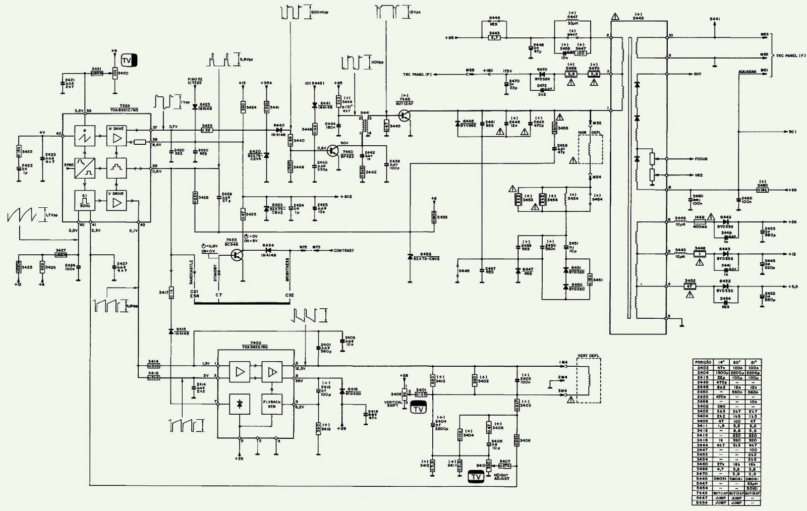
PHILIPS 20 inch CRT TV - Anubis Chassis - CIRCUIT DIAGRAM

PHILIPS ANUBIS CHASSIS CRT TV - SCHEMATIC - 20".
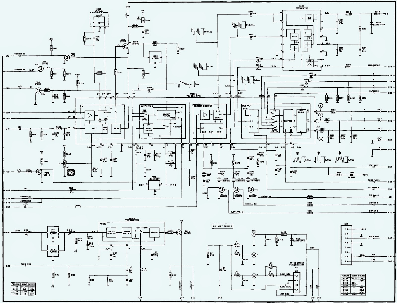
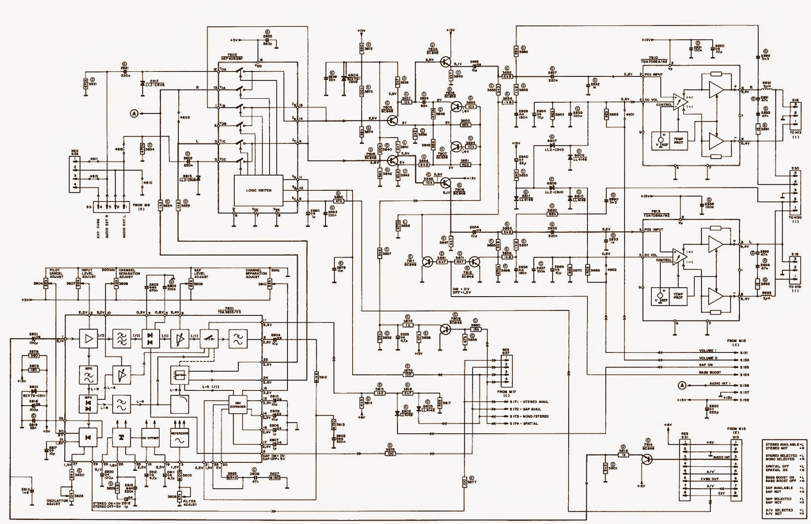
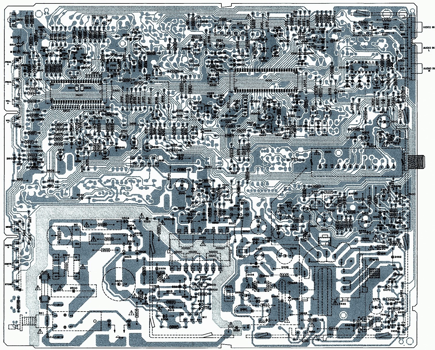
ICs used: UC3842BN (Power Control) – BST72A  - STP6N60F1(Power Switching FET) – TDA8361C/N3 (Horizontal / Vertical/ Chroma/ Synchronization / Video IF ) Jungle– TDA3653 (Vertical Scan Output) – P83C054 (System Control) – ST24C04B (System Memory) – TDA4661 – HEF4055BP – TDA7056A (Audio Output) – TDA3833/V3 (Stereo De-coder)
SYSTEM CONTROL & MEMORY
SMPS
HORIZONTAL & VERTICAL 
CHROMA
AUDIO DE-CODER & OUTPUT
PWB
CLICK ON THE PICTURES TO ZOOM IN

SYLVANIA LCT6637 - SERVICE MODE - SMPS and BACK-LIGHT INVERTER SCHEMATIC

Service Mode_Flicker Adjustment _ Initialization _ SMPS & Back-light Inverter Circuit Diagram.Used ICsOZ9938GN-B-O-T2 (Back-light inverter control) – ba10324af-e2 (Comparator) – UCC28600DR (Switching Control) – 2SK3568 (Switching output FET)
SERVICE MODE
* Use the service remote control unit.
* Turn the power on. (Use main power on the TV unit.)
* Press [SLEEP] button on the service remote control unit. The following screen appears.
To cancel the service mode, press [TV POWER] button on the remote control.
HOW TO MAKE A SERVICE REMOTE CONTROL FROM  normal remote control unit. (Part No. N0105UD or N0127UD) 
* Remove 3 Screws from the back lid.
* Add J1 (Jumper Wire) to the remote control CBA
FLICKER ADJUSTMENT
This adjustment is required when repairing T-CON CBA.
1. Enter the Service mode.
2. Press [2] button on the remote control unit. The following screen appears.
If Flicker Adjustment is not fit, the screen become the following [See the bottom picture]
Turn the VR1 on the LCD Module so that flash stops.
HOW TO INITILAIZE
1 To turn the power on, press [POWER] button on the normal remote control unit or the unit.
2 Use the service remote control unit
3 To enter the service mode, press [SLEEP] button on the service remote control unit.
 To cancel the service mode, press [TV POWER] button on the remote control.
4 To initialize the LCD television, press [DISPLAY] button on the normal remote control unit.
 “INITIALIZED” (red) appears on the screen.
 After few seconds (completion initialization), the screen is reset.
SMPS (Power) & BACK-LIGHT INVERTER SCHEMATICS
CLICK ON THE PICTURES TO MAGNIFY

SONY KDL32L504 LCD TV - HOW TO REMOVE STAND ASSEMBLY AND UNDER COVER – INVERTER – FACTORY RESET

STAND ASSEMBLY AND UNDER COVER – INVERTER – FACTORY RESET _ SONY KDL-32L504  [RM-YD028 REMOTE COTNROL]

TABLETOP STAND ASSY' and UNDERCOVER REMOVAL
* Gently place the TV set face down onto a soft cloth
* Remove 1 screw from Under Cover
* Remove 4 screws Table-Top Stand Assembly
* Slide Table-Top Stand Assembly out away from Bottom Bracket.
SPEAKER REMOVAL
* Remove 1 screw from each Speaker Baffle Plate (2 total)
* Remove 4 screws from each loudspeaker (8 total)
* Disconnect speaker wire

INVERTER BOARD REMOVAL
> Remove 5 screws from Board cover
> Pull out the Board from Lamp socket
Only remove the screws securing the inverter cover which may be metal or plastic. The remaining plastic strip contains sockets for the fluorescent backlights and should never be loosened. The backlights will pop out of the sockets and/or break the backlight requiring a LCD panel replacement. The example shown is a 32” model but applies to all models.
RESET TO FACTORY DEFAULT
Use the following instructions to restore the User Controls and Channel Memory settings to the preset factory conditions.
* While holding down the on the Remote Commander, press the POWER button on the right side of the set.
The set restarts and displays the initial setup screen.This may take several minutes.
CLICK ON THE PICTURES TO ZOOM IN

POLAROID TLM-22601B – SERVICE MODE – PASSWORD SET – SMPS SCHEMATIC

Used ICs in SMPS _ FAN7602BMK (SMPS control) – 2SK101LS (SMPS switching) – EL817MC (Photo-coupler)
SERVICE MODE & PASSWORD RESET
Turn on the TV, press MENU key with remote control, then press number key 1  9  9  9. It will achieve the factory mode.  It’s no need to adjust the white balance for this model.
PASSWORD SET
Change the 4-numeral parental control password. 
Three steps are required for changing the password. 
Enter Old Password > Enter New Password > Confirm New Password. Note: This item is only available in TV, Composite and S-Video source modes. 
The default password is [0 0 0 0]
PARENTAL CONTROL
Provide the parental Control (V-chip) function setting. Before entering the Parental Control sub-menu, user has to key in the password first. Then enter the Parental Lock item, User can modify the restricted table about MPAA or TV Rating respectively. While exiting the sub-menu, the parental control function is working.  The inhibitive channels or source signals can be un-lock through pressing the V-CHIP key on the remote control and then key in the correct password. Note: This feature is only available in TV, Composite and S-Video source modes.  (The default password is: [0 0 0 0]
Universal remote control set-up code 
{0343}
SMPS [POWER SUPPLY REGULATOR BOARD] CIRCUIT DIAGRAM
CLICK ON THE PICTURES TO MAGNIFY

SAMSUNG BN94-03052A - LCD TV POWER SUPPLY SCHEMATIC

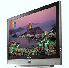
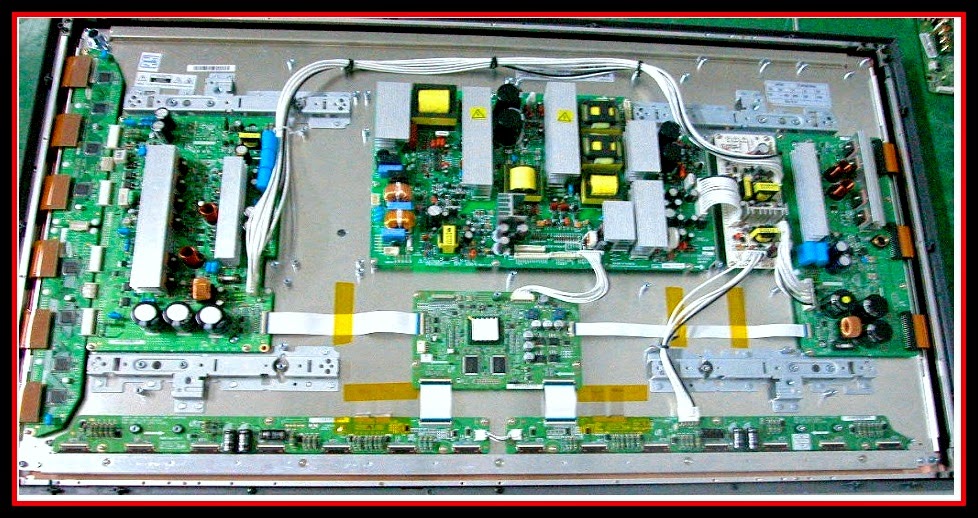
PS42D5SX - SAMSUNG PLASMA TV - FAULTS - WIRING DIAGRAM - CONNECTOR VOLTAGES

Samsung PS42D5SX/XEC - PS42D5SX/XSG - PS42D5SX/XTL Plasma Display TV - Common Faults - Wiring Diagram _ Connector pin Voltages.
THE TV IS HOT
Since a PDP TV displays a picture on the screen by discharging plasma, operating for a long time may introduce heat onto the panel. The internal heat of the panel is sent to the vent on the upper part of the product, and users must take care not to touch the hot air from the vent.  The heat from the PDP TV does not indicate a defect or problem.
NOISE FROM THE TV
A PDP TV may produce sound at a certain level when operating the fan to cool its internal temperature. In addition, since the high-speed switching circuit and the high current may produce noise depending on the screen brightness change, a PDP TV produces more noise than a conventional CRT TV.
AFTER IMAGE REMAINS ON SCREEN
Due to the nature of PDP TVs, partial after-images may appear if a still picture is displayed for a certain period of time after connecting a video game console or a computer.  This is caused by brightness deterioration due to the storage effect of the panel, and to prevent this from happening, we recommend you reduce 'brightness' and 'contrast'.
RED OR BLACK SPOTS APPEARS ON THE SCREEN
A PDP TV uses a PDP panel consisting of 123million (SD Grade) ~ 315million (HD Grade) pixels. Although a PDP panel is a product that requires high technologies to integrate a few million pixels, a bright or dark pixel may exist on the panel, this does not affect the performance of the product.
BOUNDARY APPEARS ON THE SCREEN
Displaying a still picture on the screen may permanently damage the PDP panel.
A boundary may appear due to the difference in the transparency of the panel when watching the picture in the 4:3 aspect ratios for a long time and the picture in the left, right and center screens is a still image.
A boundary may appear when watching a still picture from a DVD player or a video game console on the screen for a long time.
UNUSUAL LINES APPEARS
Keep the antenna away from the power cord or connectors if possible.
The SMPS relay repeatedly turns on and off by the protection function due to a defect on a board connected to the SMPS.
> Disconnect all cables from the SMPS, operate the SMPS alone and check if the SMPS works properly and if each voltage output is correct.
> If the symptom continues even when SMPS is operated alone, replace the SMPS.
> If the symptom is not observed when operating the SMPS alone, find any defective ASSYs by connecting the cables one by one.
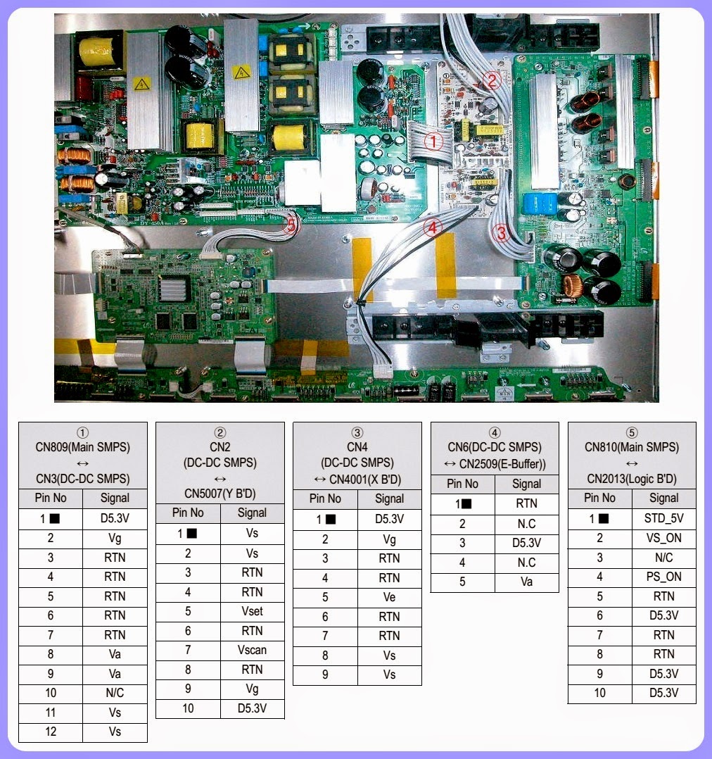
[When separating and connecting the cables such as CN809 of the Main SMPS, CN1, CN2, CN3, CN4 and CN5 of DC-DC SMPS, CN of the X Drive Board, and CN of the Y Drive Board, a spark may be generated by the electric charge of the high capacity capacitor. Therefore, wait some time after separating the power cord from the unit.]
The SMPS relay or the LEDs on the front panel do not work when connecting the power cord if the cables are improperly connected or the Video Board or SMPS is out of order. In this case, check the following
* Check the internal cable connection status inside the unit.
* Check the fuses of each part.
* Check the output voltage of SMPS.
* Replace the Video Board
TROUBLESHOOTING PROCEDURES BY ASSEMBLY
OVERALL WIRING
The Main Board – SMPS - Power Button – Speaker - Function Board Wiring - Connector pin voltages
The Main Board - SMPS, Side A/V - Sub Tuner Board - Power Button -  Speaker Out Wiring.
SMPS MODULE WIRING
CLICK ON THE PICTURES TO ZOOM IN

HOW TO TROUBLESHOOT SAMSUNG PS50C550 G1FXXY – 50inch PLASMA DISPLAY

PS50C550 G1FXXY – 50inch PLASMA DISPLAY - SAMSUNG50"PLASMA DISPLAY _ Troubleshoot _ connector Voltages _ Troubleshooting Procedures by assembly.
Universal Remote Control Set-up Codes to check with Samsung Brand TVs [All types]
TROUBLESHOOTING BY ASSEMBLY
* SMPS-PDP TV > No power, Blank screen, the Relay repeats On and Off
* ASSY PDP P-X-MAIN BOARD > Blank screen
* ASSY PDP P-Y-MAIN BOARD > Blank screen
* ASSY BOARD P-TOUCH FUNCTION&IR > The side function key does not work properly.  The remote control does not work properly, the LED does not work properly.
* ASSY PCB MISC-MAIN > No Power, Abnormal screen for each input source, PIP screen trouble, Sound trouble
* ASSY PDP P-F-BUFFER BOARD > Corresponding Buffer Board block screen is blank
* ASSY PDP P-E-BUFFER BOARD > Corresponding Buffer Board block screen is blank
* ASSY PDP P-Y-MAIN BUFFER BOARD > Lower screen is blank
* ASSY PDP P-X-MAIN BUFFER BOARD > Upper screen is blank
* ASSY PDP P-LOGIC MAIN BOARD > Blank screen, Screen noise
SCREEN-SHOTS FOR DEFECTS & POSSIBLE CAUSES
A blank vertical cell (block) appears on the screen.
Address buffer defect  - Replace the corresponding upper/lower buffers (E, F) COF defect (burnt)
> Replace the module.
A green screen appears when the TV is turned on.
> The Scale is not resetting _ Replace the Main board.
The OSD box appears but there is no text. Incorrect program version
> Check the version of each program
> Replace the Main board
A blank upper (or lower) block appears on the screenUpper/Lower Y Buffer defect
> Replace the corresponding upper/lower buffers.
Either the main or sub picture does not appear.
> Replace the Main board
A vertical green line appears on the screen.  The SMPS voltage is incorrect
> Adjust the SMPS voltage according to the voltage printed on the module label
Dim screen (blurred in red)  X-Main board defect
> Replace the X-Main board
Va & Vs voltage adjustment
After replacing the SMPS or PDP panel, you must adjust the voltage referring to the voltage label printed on the panel. (If you do not adjust the voltage, an abnormal discharge symptom may appear.)
CONNECTOR ROLE & PIN VOLTAGES
UNIVERSAL REMOTE CONTROL SET-UP CODES
0030 0049 0050 0066 0076 0101 0102 0119 0143 0152 0154 0166 0181 0195 0209 0217 0240 0307 0318 0365 0379 0414 0421 0488 0492 0601 0624 0637 0642 0827
CLICK ON THE PICTURES TO ZOOM IN


PS42D - SAMSUNG PLASMA DISPLAY SMPS - VOLTAGES - DETAILS

SAMSUNG PS42D5SX/XEC_PS42D5SX/XSG_PS42D5SX/XTL _ SMPS [Power supply regulator board] – VOLTAGES – PROTECTIONS
SAMSUNG 42"& 50" PLASMA TV - SMPS OUTLINE
   Considering various related conditions, the switching regulator with good efficiency and allowing for its small size and light weight was used as the power supply for PDP 42" (Schubert) / 50" (Strauss), VS requiring high power consumption Asymmetrical Half Bridge converter and fly back converter. To comply with the international harmonics standards and improve the power factor, active PFC (Power Factor Correction) was used to rectify AC input into +400V DC output, which in turns used as input to the switching regulator.
An output short circuit is defined as output impedance of less than 300Mohms.    The power supply shall shutdown and latch off for shorting VS DC rails to return. Shorts between main output rails and STD_5V shall not cause any damages to the power supply.  The power supply shall either shutdown and latch off for shorting is removed, the P/S shall recover. The power supply shall be capable of withstanding a continuous short-circuit to the output without damage or over stress to the unit (components, PCB traces, connectors, etc.) under the input conditions specified in Section 3 above. Current Protection as defined below.
   The over voltage sense circuitry and reference shall reside in package that are separate and distinct from the regulator control circuitry and reference. No single point fault shall be able to cause a sustained over voltage condition on any of all outputs. The supply shall provide latch-mode Over Voltage Protection as defined below.
INPUT
   The power supply shall be capable of supplying full rated output power over free voltage ranges that are rated 100 VAC - 240 VAC RMS nominal. Operating voltage : 90 VAC - 264 VAC The power supply must be able to start up under peak loading at 90VAC. The power supply shall automatically recover from AC power loss. (Note that nominal voltages for test purposes are considered to be with +/- 1.0V of nominal).  STD_5V & Vpr2 (3.3V) is a SELV standby voltage that is always present when AC mains voltage present.
[Normally there is no repair to these SMPS boards, except for damaged or bulged main filter capacitor replacement.  It is advised to replace it as card basis.  After SMPS board replacement, Va & Vs voltages to display panel should be adjusted as per indication at the silk-screen at the panel.  These voltages will differ to panel to panel.]
CLICK ON THE PICTURES TO MAGNIFY

SAMSUNG BN-96 SCHEMATIC - Bordeaux - Ver-1 and Ver2 - LCD TV SMPS

MC-261 - MICRO-SYSTEM – SCHEMATIC (Circuit Diagram) FULL

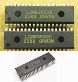
CHINESE COLOR TV KIT - SERVICE HELP - LA76810 - LC86353

USED ICs: AT24C04/08 (System Memory) – LC86353 (Main System Control) – LA76810 or LA76818A (Horizontal_Vertical_Chroma_VIF _Sync-Seperator Jungle) – AN17821A (Audio Output) – LA78040 (Vertical Output) – BSC24-0144014K / BSC-09N20E LOT)
SET DEAD.  NO POWER
  When switch ON, there is no power light or any other indication.  Sometimes, the Power LED may light up, and shut down atonce.
The power supply section circuit to this kit has short circuit protection.  By anyway, any short circuit occurs at the main board, the power won’t switch ON.  The main cause found to this circuit is with shorted Horizontal Output Transistor [2SD1651C / 2SD2499; (Collector to Emitter or Collector to Base; short).  The best way to troubleshoot is, just de-solder out the horizontal output transistor from the PWB, and just switch ON the set, and see whether the Standby Light is ON.  If it does, make sure that this transistor is damaged.
Before replacing this transistor, just check for any other reason for its failure.  The C435 & C438 should be checked with a capacitance meter for its capacity.  It will be best to replace both of them at the same time, along with the horizontal output transistor.  Even loose solder terminals at these capacitor terminals will surely make the H-Out transistor get shorted.  Check VD435 & VD436 and C437 too.  Without checking all these components and its soldering thoroughly, never switch on the set with a new H-Out transistor.
  The next possibility for H-out transistor failure is; it’s loose seating screw with the heat sink.  Another one is with shorted winding [Horizontal section] of the deflection yoke.  Other is HOT [Horizontal Output Transistor; otherwise called as LOT BSC24-01N4014K / BSC25-09N20E.  Check all the solder terminals to the leads of this Line out Transformer [LOT] too, for any loose soldering.
  If deflection yoke winding has any short (this short can’t be measure by normal technique or with a multimenter); it should be replaced before switch on the set.  You can switch ON the set without this deflection yoke connection; but; must unplug the CRT base card from the CRT base; otherwise there is a chance to make a dark spot at the center of the screen due to accelerated beam of electrons inside the CRT, without any scanning.  It will fall straight at the center of the screen itself, provided the LOT and H-Out transistor as well as the SMPS is OK.  Be sure about this, when you switch on the set without deflection yoke connection.  This is true to any CRT based televisions; irrespective of its brand and size.
  If the horizontal output transistor is found damaged, check the load resistor R551 2.2Ohms 2W W/W for open.  In most cases, this won’t happen to this kind of circuit, as any short circuit occurs at the secondary stage of the SMPS will clause the SMPS to shut down instantaneously.
  In practice, this is the most venerable fault that can occur to sets fitted with this kit.  90% of it I did faced was it. 
  If the LOT is defective (Internal short in its winding), the horizontal output transistor will heat up within seconds.  To make this sure, just switch ON the set, and see whether the standby light lights up.  If it does, just switch it OFF after 30 or 40 seconds, and unplug the set from AC mains wall socket, and feel the heat of the horizontal output transistor with bare fingers.  It can be slightly warm, but not too hot.  This effect can due to a damaged deflection yoke too.
 It is advised to re-solder all the terminals of IC LA76810 / LA76818A; because this IC will heat up to an extent while the set works, and repeated heating and cooling can make its solder terminals to expand and shrink; and make any loose solder terminals, so microscopic to see with naked eye.  It is be best to suck out the solder from each terminal; using a solder suction pump and re-solder it by applying fresh solder, without making any solder bridge short in between.  Be very careful.  After soldering the IC terminals, clean it using Medical Quality Turpentine or Rectified Spirit. 
  In most cases, the main system control IC found OK.  Do not do any unwanted checks and meter prods touches to it; when power is ON.  This is a very sensitive IC; can be damaged easily.
  The SMPS circuit to this set is quite simple related to STR based ones, and is easy to follow.  I’ve here described some service experiences of mine with this type of kit.  There might be more to describe for others.  Service experiences to person to person will be different indeed.
SCHEMATIC
CLICK ON THE SCHEMATIC TO ZOOM IN

DELL W2607C LCD TV - HOW TO ENTER SERVICE MODE – ADJUSTMENTS – DISASSEMBLE – POWER SCHEMATIC

How to disassemble Dell W2607C LCD TV – SMPS Schematic – Service Mode
Used ICs in SMPS: FAN5500AN _ NCP1377 _ STP10NK80ZFP(Power Switching MOSFET) _ PC123FY2 4P (Photo-coupler) _ AD4411 _ SCR 2N5060 _ ST8120 _ STR-A6252  
SERVICE MODE
* No OSD pictures on screen, Press Number key 2> 4> 8> 6> MENU> INFO in Remote Control will access into the factory mode. (Service Mode)
* Press MENU button to quit from factory mode.
In the factory mode:
The data is the result of R  G  B after W/B adjustment:
5700K R G B
6500K R G B
9300K R G B
NATURAL R G B
NVRAM Init > Initial EEPROM
Burn in mode On/OFF

WHITE BALANCE ADJUSTMENT 

Initial the EEPROM
> Press “NVRAM Init: Press  “OK”  to start” to initial EEPROM.
Bias (Low luminance) adjustment
Ensure the currently mode is PC (VGA)
Press “Auto Balance” button (the image is black and white at the PAT42)
GAIN ADJUSTMENT
> Switch the chroma-7120 to RGB-mode (with press “MODE” button)
> Let the signal output the white image (press pattern 105), select one of the color temp (as Natural、 6500K、9300K、 5700K) and adjust factory mode window R  G  B until up to the value Chroma7120 R, G, B=100± 3.
> Select another color temp and follows as item 2.
AV W/B adjustment
Gain adjustment
> Switch the chroma-7120 to RGB-mode (with press “MODE” button)
> Let the signal output the white image (press pattern 105), select one of the color temp (as Natural、 6500K、9300K、 5700K) and adjust factory mode window R  G  B until up to the value Chroma7120 R, G, B=100± 3.
> Select another color temp and follows as item 2.
SV(S-Video) W/B adjustment
the steps of SV’s W/B adjustment is the same as AV’s.
(component) W/B adjustment
the steps of CP’s W/B adjustment as same as PC’s.
Max Brightness measurement
* Switch to the full white pattern, in normal mode main menu
* Set “Picture Settings” menu Brightness, Contrast to the max.
The Minimum brightness is 400cd/m².
DISASSEMBLE PROCEDURE
Remove Stand and base & Back cover
Lay LCD-TV on a flat, soft and clean surface.
> Remove 4 screws to remove stand and base.
> Remove 4 screws at the top of the back cover. Fig.2
> Remove 2 screws at the left top of the back cover. Fig.3
> Remove 2 screws at the right top of the back cover. Fig.4
> Remove the connector wire of back cover and interface board
Remove the shield
* Remove 8 screws of the shield at the top and bottom shield. Fig. 6
* Remove 2 screws of the shield at the left. Fig. 7
* Remove 1 screw of the shield at the right.
SMPS (Power Supply Regulator) Circuit diagram
CLICK ON THE PICTURES TO ZOOM IN

Viewing all 2033 articles
Browse latest View live


<script src="https://jsc.adskeeper.com/r/s/rssing.com.1596347.js" async> </script>