KV DA322M66 – KV DA322M64– RESET – SMPS and DEFLECTION SCHEMATIC _ Picture Distortion Adjustments _ SONY Wega Trintron Flat TV

If you faces some setting problem that cannot be solved, using the "RESET" function some items will be reset to its original setting or factory setting (shipping condition).
How to OperateThe following is to show on how to access to the "RESET" Function
User selection = press 'WEGA GATE' => select =>'SETTING' => go to 'SETUP' page => select 'FACTORY SETTINGS' => select 'YES'.
User selection = press 'WEGA GATE' => select =>'SETTING' => go to 'SETUP' page => select 'FACTORY SETTINGS' => select 'YES'.
Sequential to the resetting operation, TV set would shut down once and automatically turn on again. The power-off duration is expected to be about 500msec. Initial Setup Menu is displayed. As a result, some items will be reset to their initial conditions (shipment condition) whereas some others remain at the last user selection.
ITEMS THAT REMAIN AT THE LAST USER SELECTION
Program No., PICTURE POSITION (included PICTURE ROTATION and PICTURE V-POSITION), OSD Language, Fine tuning, TV System, Skip, Program label, Program sorting, Video label.
ADJUSTMENT TO A1 BOARD, AFTER MEMORY IC [IC003] REPLACEMENT
1Enter to Service Mode. {With the unit on standby > [DISPLAY] => 5 => [VOL(+)] => [POWER}
2 Press commander buttons 5 and - (Data Initialize), and 2 and - (Data Copy) to initialize the data.
3 Call each item number and check if the respective screen shows the normal picture. In cases where items are not well adjusted, rectify the items with fine adjustment. Write the data per each item number [Muting + 0)
4 Select item numbers “OPB00” (OP1), “OPB01” (OP2) and respectively set the bit per model with command buttons 3 and 6.
5 Press commander buttons 8 and - (Test Normal) to return to the data that was set on the shipment from the factory. (This will also cancel Service Mode.)
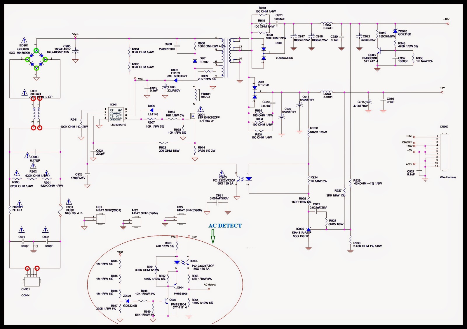
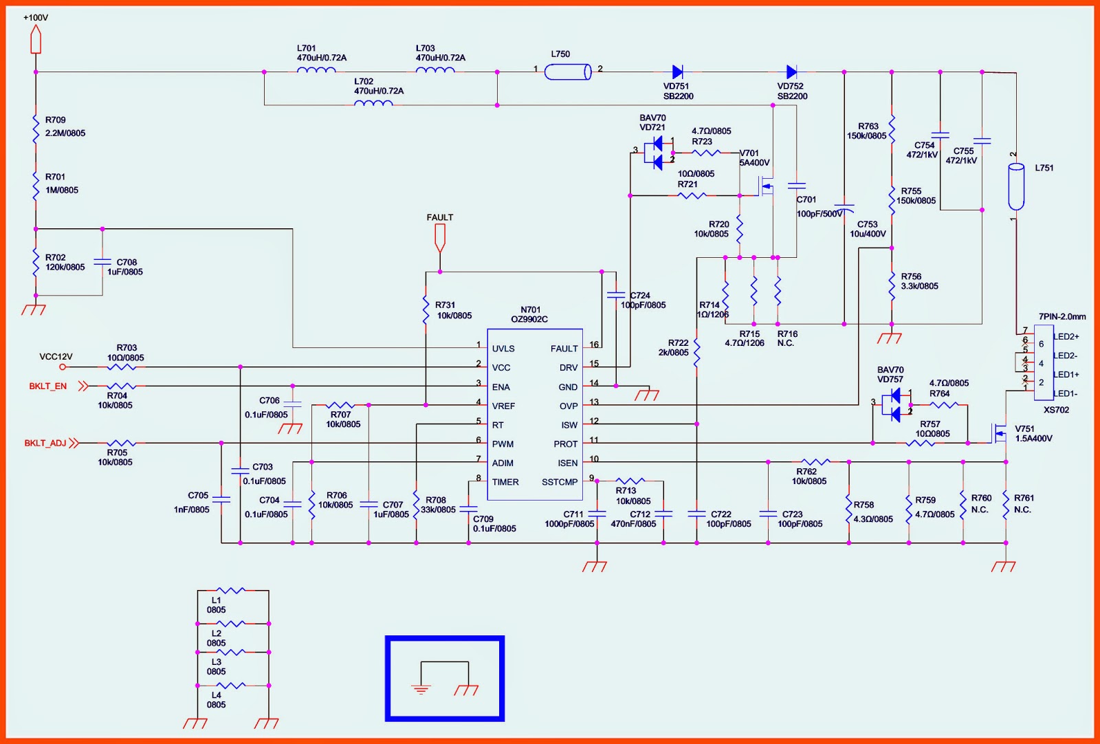
PICTURE DISTORTION ADJUSTMENTS

D-BOARD [Power Supply & Deflection] schematic (Circuit Diagram)
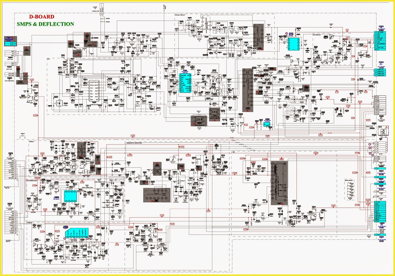
CLICK ON THE PICTURES TO ZOOM IN