Quantcast
Channel: Electro help
Viewing all 2033 articles
Browse latest View live

LINE FAULTS TO PLASMA TVs

$
0
0
What is Plasma?
Plasma is by far the most common form of matter.
Plasma in the stars and in the tenuous space between them makes up over 99% of the visible universe and perhaps most of that which is not visible.  Plasma consists of a collection of free-moving electrons and ions - atoms that have lost electrons.
Energy is needed to strip electrons from atoms to make plasma. The energy can be of various origins: thermal, electrical, or light (ultraviolet light or intense visible light from a laser).  With insufficient sustaining power, plasmas recombine into neutral gas.
Plasma can be accelerated and steered by electric and magnetic fields which allows it to be controlled and applied. Plasma research is yielding a greater understanding of the universe.
It also provides many practical uses: new manufacturing techniques, consumer products, and the prospect of abundant energy.
What is Plasma Display Panel - How does it work?
Plasma display panel is the latest display technology and the best way to achieve flat panel displays with excellent image quality and large screen size that is easily viewable in any environment.  PDP is an array of cells, known as pixels, which are composed of 3 sub-pixels, corresponding to the colors Red, Green and Blue. Gas in a plasma state is used to react with phosphors in each sub-pixel to produce colored light (red, green or blue). These phosphors are the same types used in Cathode Ray Tube(CRT) devices such as televisions and standard computer monitors. You get the rich, dynamic colors that you expect.  Each sub-pixel is individually controlled by advanced electronics to produce over 16 million different colors.  All of this means that you get perfect images that are easily viewable in a display that is less than 6 inches thick.
LINE FAULTS ON SCREEN
Vertical bar when Power off/on (Mis-discharge)
PDP Power on Mode external input (regardless of wire/wireless signal but it’s easy to reenact in wireless signal)
Remove Power Cord (Power’s off) After about 20minutes, insert Power cord (automatically the Power’s on and the vertical bar is .

Cause Control board malfunctions when Power off/on.
Countermeasure Change some parts on Control board.
Changing parts  A32_CTRL_03 B/D (Marked on PCB) -.R14,17,18,21 : 330 > 4.7K (Chip Resistor) -R15,16,19,20 : 22K > 4.7K (Chip Resistor) -.C504, 505 : 0.1uF / 50V add (Chip Capacitor)
Add Open (Green 1 Line) > Add. COF Drive IC inferior.
Symptom
No signal Vertical Bar.
* IC2 DA1(Data Arrange) No.162 Pin output is changing depending on the temperature.⇒ abnormal X-B’d Buffer IC * Room temperature : 2.5V Output (Normal Pin = over 2.8V) * Heated : 1.5V Output(Normal Pin = 2.7V ) ⇒ Bad IC2 (DA1)
Countermeasure Replace IC2
Screen is divided in top and bottom, and vertical bar appears.
P13 CONNECTOR contact point inferior CHECK.
P13 CONNECTOR SIGNAL CHEK.
ADDRESS bar appears in the right bottom of the screen. (X-BOARD BOTTOM LEFT)
The connecting of X-Board bottom left connector is bad.  Reassemble it.
The 2/5 right part of the screen is blank. (Bottom left X-BOARD )
No 12V supply to bottom left X-Board.  Connect 12V line.
Check 12V line from SMPS to X-BOARD.
The 2/5 right of the screen is broken. (Bottom left X-BOARD)
Check Bottom left X-BOARD 5V.( If 0V, it happens )
Check 5V line from SMPS to X-BOARD
The 3/5 bottom left of the screen is Blank. (Bottom Right X-BOARD)
No 12V supply to bottom right X-Board.
No Va(70V) supply to bottom right X-Board.
CLICK ON THE PICTURES TO MAGNIFY


LOT Internal Winding DATA For SAMSUNG KONKA and CHINESE KIT LOTs

$
0
0
Samsung LOT _ FCM14A025 _ Data; TCL LOT _ JF0501-1914 _ Data _ China Brand  LOT _ BSC24-014001D BSC25-N0321 BSC25-N1534 BSC25- N1634 BSC25-Z1003 BSC25-Z2705 BSC25-Z2706 BSC25-N0313 _ Data _ China Brand LOT_ BSC24-014001D BSC25-N0321 BSC25-N1534 BSC25-N1634 BSC25-Z1003 BSC25-Z2705 BSC25-Z2706 BSC25-F1125A _ Data _ Konka LOT_ BCS25-N1603 BSC25-0113 BSC25-023D _ Data _ Konka LOT_ BCS25-N1603 BSC25-0113 BSC25-2678S _ Data
Samsung LOT _ FCM14A025 _ Data
Samsung LOT _ FCM2014FL _ Data
TCL LOT _ JF0501-1914 _ Data
China Brand  LOT _ BSC24-014001D BSC25-N0321 BSC25-N1534 BSC25-
N1634 BSC25-Z1003 BSC25-Z2705 BSC25-Z2706 BSC25-N0313 _ Data
China Brand  LOT BSC25-F1125A _ Data
Konka LOT_ BCS25-N1603 BSC25-0113 BSC25-023D _ Data

Konka LOT _ BCS25-N1603 BSC25-0113 BSC25-2678S _ Data
CLICK ON THE PICTURES TO ZOOM IN

LOT WINDING DATA Hitachi Sansui Toshiba Solidtron Sharp Samsung and Gold Star CTVs

$
0
0
Flyback Transformer Data Hitachi  Sansui  Toshiba  Solidtron  Sharp  Samsung Gold Star  Panasonic
Flyback TLF15644F1 Panasonic
TLF4N052 TLF4G503F
Flyback 154-177B Goldstar
154-064P FCK-14B047 JF0501-1206 JF0501-91802 154- 374A 6174Z-6238L
Flyback FOK14A001 Samsung
AA26-002101A FSV-14A004C
Flyback F0193PEN1-SA Sharp
F0194PEN1-SA F0147PE-M BCS21-2647 F0101KMSA F0102KM F02299PE-B F0141PE-M
Flyback FSV20A099 Sanken
Flyback 2435521 Hitachi
Flyback TFB4122BD Toshiba
TFB4125CH
Flyback DCF-2077D Solidtron
DCF-2077A DCF-1577 FSA16012M
Flyback JF0501-1206 Sansui
154-177B 154-064P FCK-14B047 JF0501-91802 154-374A 6174Z- 6238L
CLICK ON THE PICTURES TO ZOOM IN

JBL SB 300 – SB 230 Powered Sound Bar SCHEMATIC

$
0
0
JBL SB 300 – SB 230 - Powered Sound Bar  with Wireless Powered Sub-woofer. Specifications _ Circuit Diagram _ Connection Diagram
SB300 - POWERED SOUNDBAR SPEAKER-Specifications
Low-frequency transducer: Two 2" (51mm) cones per channel, videoshielded
High-frequency transducer: One 1" (25mm) dome per channel, videoshielded
Amplifier power: 30 watts per channel
Audio controls: Volume, surround mode
Connections: Optical digital (TOSLINK™) input, stereo
analog (RCA-type) inputs
Power requirement: 120V – 240V, 50Hz/60Hz, 80W
Power consumption: 1W standby; 80W maximum
Dimensions (H x W x D): 3-5/8" x 45-3/4" x 3"
(92mm x 1162mm x 76mm)
Weight: 5.5 lb (2.5kg)
SB300 SUBWOOFER SPECIFICATIONS
Low-frequency transducer: 8" (200mm) cone, down-firing
Enclosure type: Ported (down-firing)
Amplifier power: 100 watts
Frequency response: 42Hz – 200Hz (–3dB)
Audio controls: Level, phase, cutoff frequency
Connections: LFE input, left and right RCA line-level inputs
Power requirement: 120V – 240V, 50Hz/60Hz, 160W
Power consumption: 1W standby; 160W maximum
Dimensions (H x W x D): 19" x 14-1/4" x 14-1/4"
(483mm x 362mm x 362mm)
Weight: 24.5 lb (11.1kg)
SOURCE CONNECTIONS
analog: Use the supplied stereo audio cable to connect the soundbar’s Source 1 (analog) input to your TV’s stereo audio output. If your TV has two sets of audio output jacks, use the set that has a fixed (not variable) output level. This will let you turn your TV’s speakers all the way off while the TV still supplies a constant audio signal to the soundbar.  digital: If your DVD player, cable tuner or satellite tuner has an optical digital output, you can use an optical digital audio cable to connect it to the soundbar’s Source 2 (optical digital) input.
TURNING THE SUB-WOOFER ON & OFF
Set the subwoofer’s Power switch to the “On” position. The subwoofer will automatically attempt to establish pairing with the soundbar (the subwoofer’s LED will flash blue). If pairing is not established within one minute, the subwoofer will enter the Standby mode (its LED will turn amber). If pairing is established, the subwoofer will turn on (its LED will light blue continuously).  The subwoofer will remain on for approximately one minute after the soundbar enters the Standby mode, or for approximately 15 minutes after the audio signal ceases.
CIRCUIT DIAGRAMS[Click on the pictures to Magnify]

SUB550P JBL Amplifier Sub-woofer - Schematic - Specifications

$
0
0
JBL SUB 550P / 230Amplifier/Subwoofer – Controls & connections – SMPS & Amplifier Schematic (Circuit diagram)
SUBWOOFER REAR-PANEL CONTROLS AND CONNECTIONS
Phase switch: This switch determines whether the subwoofer driver’s piston-like action moves in and out in phase with the system’s other speakers. If the subwoofer were to play out of phase with the other speakers, the sound waves from the other speakers could partially cancel out the sound waves from the subwoofer, reducing bass performance and sonic impact. This phenomenon depends in part on the placement of all the speakers relative to each other in the room.
Input Mode switch: When this switch is in the “Normal” setting, the input signal from the Line In connectors is active. When this switch is in the “LFE” setting, the input signal from the LFE In connector is active, and the subwoofer’s internal crossover is bypassed.
Level control: Use this control to adjust the subwoofer’s volume. Turn the knob clockwise to increase the volume; turn the knob counterclockwise to decrease the volume.
Crossover control: This control determines the highest frequency at which the subwoofer reproduces sounds. The higher you set the Crossover control, the higher in frequency the subwoofer will operate and
the more its bass will “overlap” that of the system’s other speakers. This adjustment helps achieve a smooth transition of bass frequencies between the subwoofer and the other speakers for a variety of different rooms and subwoofer locations. NOTE: The Crossover control functions only when the Input Mode switch is in the “Normal” position. When the switch is in the “LFE” position the subwoofer’s built-in crossover and Crossover control are bypassed.
On/Standby indicator: This LED indicates whether the subwoofer is in the On or Standby state:
* When the LED glows green, the subwoofer is turned on.
* When the LED glows red, the subwoofer is in the Standby mode.
* When the LED is off, the subwoofer’s Power switch is set to “Off.”
SUB 550P BASIC SPECIFICATIONS
Low-frequency transducer: 10" (250mm) PolyPlas cone, cast basket
Enclosure type: Sealed (forward-firing)
Amplifier power: 300 watts (RMS); 500 watts (peak)
Frequency response: 27Hz – 150Hz
Audio controls: Volume level, crossover frequency, phase
Connections: RCA line-level and LFE inputs
Power requirement: 120V, 60Hz (US); 220V – 230V, 50Hz/60Hz (EU)
Power consumption: <6W (120V) standby 360W (3.8A @ 120V) maximum <0.55W (230V) standby 395W (2.1A @ 230V) maximum 
Dimensions (W x H x D): 17-1/2" x 14-29/32" x 14-31/32" (444mm x 379mm x 380mm)
Weight: 50 lb (23kg)
PLACING THE SUBWOOFER
The performance of a subwoofer is directly related to its placement in the listening room and its physical position relative to the other speakers in the system.
While it is true that in general our ears do not hear directional sounds at the low frequencies where subwoofers operate, when installing a subwoofer within the limited confines of a room, the reflections, standing waves and absorptions generated within the room will strongly influence the performance of any subwoofer system. As a result, the specific location of the subwoofer in the room does become important to the amount and quality of bass that is produced.
For example, placing the subwoofer next to a wall generally will increase the amount of bass in the room; placing it in a corner (1) generally will maximize the amount of bass in the room. However, corner placement can also increase the destructive effect of standing waves on bass performance. This effect can vary depending on the listening position – some listening positions may yield very good results while others may have far too much (or too little) bass at certain frequencies.  In many rooms, placing the subwoofer along the same plane as the left and right speakers (2) can produce the best integration between the sound of the subwoofer and that of the left and right speakers. In some rooms, the best performance could even result from placing the subwoofer behind the listening position (3).
Experiment with placement before choosing a final location for your subwoofer. One way you can determine the best location for the subwoofer is by temporarily placing it in the listening position and playing music with strong bass content. Move around to various locations in the room while the system is playing (putting your ears where the subwoofer would be placed), and listen until you find the location where the bass performance is best. Place the subwoofer in that location.
CONNECTING THE SUBWOOFER
TURNING THE SUBWOOFER ON AND OFF
Set the subwoofer’s Power Switch to the “On” position. The subwoofer will automatically turn itself on when it receives an audio signal, and it will go into Standby mode after it has received no audio signal for approximately 10 minutes. The subwoofer’s LED will glow green when the subwoofer is on and will glow red when the subwoofer is in Standby.  If you will not be using the subwoofer for an extended period – for instance, if you’re going on vacation – set the Power Switch to the “Off” position.
SUBWOOFER ADJUSTMENTS: CROSSOVER CONTROL
NOTE: The Crossover control functions only when the Input Mode switch is in the “Normal” position.
The Crossover control adjusts the subwoofer’s built-in low-pass filter crossover between 50Hz and 200Hz. The higher you set the Crossover control, the higher in frequency the subwoofer will operate and the more its bass will “overlap” that of the satellite speakers. This adjustment helps achieve a smooth transition of bass frequencies between the subwoofer and the satellites for a variety of different rooms and subwoofer locations. To set the Crossover control, listen for the smoothness of the bass. If the bass seems too strong at certain frequencies, try a lower Crossover control setting. If the bass seems too weak at certain frequencies, try a higher Crossover control setting.
SUBWOOFER ADJUSTMENTS: VOLUME
Use the Level control to set the subwoofer’s volume. Turn the knob clockwise to increase the subwoofer’s volume; turn the knob counterclockwise to decrease the volume. Once you have balanced the subwoofer’s volume with that of the other speakers in your system, you shouldn’t have to change the Level control setting.
Notes on Setting Subwoofer Volume:
SOMETIMES THE IDEAL SUBWOOFER VOLUME SETTING FOR MUSIC IS TOO LOUD for films, while the ideal setting for films is too quiet for music. When setting the subwoofer volume, listen to both music and films with strong bass content and find a “middle ground” volume level that works for both.
IF YOUR SUBWOOFER ALWAYS SEEMS TOO LOUD OR TOO QUIET YOU MAY WANT
to place it in a different location. Placing the subwoofer in a corner will tend to increase its bass output, while placing it away from any walls or corners will tend to lessen its bass output.
SUBWOOFER ADJUSTMENTS: PHASE
The Phase switch determines whether the subwoofer driver’s piston-like action moves in and out in phase with the satellite speakers. If the subwoofer were to play out of phase with the satellite speakers, the sound waves from the satellites could partially cancel out the waves from the subwoofer, reducing bass performance and sonic impact. This phenomenon depends in part on the placement of all the speakers relative to each other in the room.  Although in most cases you should leave the Phase switch in the “Normal” position, there is no absolutely correct setting for the Phase switch. When the subwoofer is properly in phase with the satellite speakers, the sound will be clearer and have maximum impact, and percussive sounds like drums, piano and plucked strings will sound more lifelike. The best way to set the Phase switch is to listen to music that you know well and to set the switch in the position that gives drums and other percussive sounds maximum impact.
SCHEMATICS
CLICK ON THE PICTURES TO ZOOM IN

SHARP LC-19S7EBK - LC-26S7EBK - LC-32S7EBK - How to enter Service Mode - SMPS SCHEMATIC

$
0
0
Sharp 19 Inch_Sharp 26 Inch and Sharp 32 Inch LCD TV _ Service Mode _ Power Supply Circuit Diagram _Software Upgrade
SERVICE MODE [FACTORY MODE]
To enter factory mode menu: Press the key “1999” on remote control.
Press ▲/ ▼ to choose the value
Press OK to fix the value.
Press OK to exit the factory mode when choose “EXIT” option.
SOFTWARE UPGRADE PROCEDURE
Connect to TV USB port to upgrade the software firmware.
* Copy the software firmware (*.bin) to USB Disk.
* Insert the USB Disk to TV USB port.
* Unplug the AC cord.
* AC power on
* Reboot TV to update SW automatically. During upgrade FW the front LED will red light blink.
* When FW upgrade is finished LED will stop blinking and keep at (Blue + red) color.
After finish upgrade process.
* Remove USB disk from TV.
* Turn AC Off then On to reboot TV
19" LCD TV  SMPS & BACK-LIGHT INVERTER SCHEMATIC
26 and 32 INCH LCD TV_SMPS SCHEMATIC _ PWB Top & Bottom views
CLICK ON THE PICTURES TO MAGNIFY

HYUNDAI CTV HY1418NF – REPAIR HELP From my SERVICE TABLE TODAY

$
0
0
Used IC TDA1105PS [Syscon-VIF-Oscillator-Chroma jungle.] (Chinese KIT)

LOT number: BSC 25-N0625
  The set do not starts up.  The power LED blinks continuously.  A clear evidence; that the fault is with main board circuit itself.  The SMPS section circuit is OK.  Otherwise, the power LED won’t light up.
On checking further, a multi-meter test revealed that the Collector to Emitter junction of the Horizontal Output Transistor [HOT] (D1651C] is Leakey.
Shows about 3 Ohms DC resistances across these two terminals.  Un-soldered it out from the circuit and measured again.  The leak confirmed.
 Now powered ON the set without this transistor and checked the +B voltage.  If it is more than normal, this could happen.  Without confirming this voltage to be OK, if we replace this transistor with another new one; surely it too will get damaged within minutes.
The +B voltage was OK.  At bout 111.5VDC; without load [w/o Horizontal Output Transistor]. 
Replaced the Horizontal Output Transistor with its exact substitution (C5296); as D1651C was not available.  Switched ON the set.  OK.
The raster (Blue screen) appeared.  But; it blinks occasionally; along-with a sparking noise.
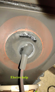
On further checking; I found that the EHT cap (Boot) has burned, and causes sparking.
Replaced this Silicon Rubber Boot with a new one.
Switched ON the set.  No other problem detected.
Tuned in an on-air program.  Perfect picture.
Attention: Before you unclip the EHT boot, make sure that the storage voltage at the final Anode has been discharged fully; otherwise severe shock hazard be the result.
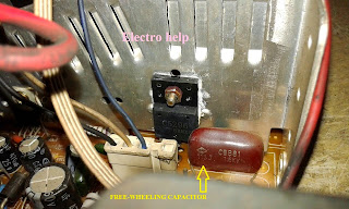
Be sure that there is no loose soldering to the free-wheeling capacitor; connected between Collector terminals of the Horizontal Output Transistor to Ground. [0.01MFD – 1.6KV].  Either this capacitor is open; or any of its solder terminals [2 of it] has loose solder, no doubt, the Horizontal Output Transistor will get damaged; at the instant we switch the set ON.
CLICK ON THE PICTURES TO MAGNIFY

JBL HOME THEATER SYSTEM CS 460 AND CS 680 SCHEMATIC (Circuit Diagram)

$
0
0
Home Theater System_JBL CS460 _ JBL CS680 _ Specifications and Circuit Diagram
SPECIFICATIONS
CS460 - SATELLITES
Frequency Response (– 6dB): 110Hz – 20kHz
Recommended Amplifier Power Range: 10 – 100 Watts
Sensitivity (2.83V @ 1 meter): 86dB
Nominal Impedance: 8 Ohms
Crossover Frequency: 3.0kHz; 12dB/Octave
High-Frequency Driver: 13mm (1/2") Titanium-laminate dome, magnetically-shielded
Midrange Driver: 89mm (3-1/2"), magnetically shielded
Dimensions (H x W x D): 152mm x 162mm x 98mm (6" x 6-3/8" x 3-7/8")
Weight: 0.9kg (2.0 lb)
CENTER
Frequency Response (– 6dB): 100Hz – 20kHz
Recommended Amplifier Power Range: 10 – 100 Watts
Sensitivity (2.83V @ 1 meter): 88dB
Nominal Impedance: 8 Ohms
Crossover Frequency: 3.0kHz; 12dB/Octave
High-Frequency Driver: 13mm (1/2") Titanium-laminate dome, magnetically-shielded
Midrange Driver: Dual 89mm (3-1/2"), magnetically shielded
Dimensions (H x W x D): 133mm x 289mm x 86mm (5-1/4" x 11-3/8" x 3-3/8")
Weight: 1.5kg (3.2 lb)
SUBWOOFER
Frequency Response (– 6dB): 38Hz – 160Hz
Amplifier: 125W RMS/250W Peak†
Driver: 170mm (6")
Dimensions (H x W x D, including feet): 394mm x 273mm x 305mm (15-1/2" x 10-3/4" x 12")
Weight: 11kg (24.5 lb)
CS600SAT
Frequency Range (–6dB): 100Hz – 20,000Hz
Recommended
Amplifier Power Range: 10 – 100 Watts
Sensitivity (2.83V @ 1 meter) 88dB
Nominal Impedance: 8Ω
Crossover Frequency: 3.0kHz; 12dB/octave
Midrange Driver: Dual 3-1/2" (89mm) magnetically shielded
High-Frequency Driver: 1/2" (13mm) Titanium-laminate, magnetically shielded
Dimensions (H x W x D): 11-3/8" x 5-5/8" x 3-3/8" (289mm x 131mm x 86mm)
Weight: 3.2 lb (1.5kg)
SCHEMATIC{Click on the Schematics to Zoom In}
POWER AMP PWB


AKIRA 21BSS3Ve 21BSS3Wn CRT TV Troubleshooting and circuit diagram Service Mode

$
0
0
AKIRA 21BSS3 CRT TV - HOW TO TROUBLESHOOT – Schematic Diagram – Service Mode [Factory Mode] – Default Data Values
SERVICE MODE [Factory Mode] TB 1238 SERIES I2C BUS CONTROL - TO 
* Press the numeric keys, switch to the position 12
* Press the numeric keys again, switch to the position 38
* Press the MENU key to call up the POS.LOCK menu
* Press the MUTE key
* Press the numeric key to input the password 1, 2, 3, 8. Then the TV will enter into the factory mode while the "M" displayed on the top of the screen.
* Under adjusting mode, you can select the item you want by pressing the / keys and you can adjust the value of the items when you press the / keys.
DEFAULT DATA VALUES
CLICK ON THE PICTURES TO ZOOM IN
TROUBLESHOOTING
No OSD (On Screen Display)
This failure is usually cause by the circuit of character generated and located. Most of reasons are that the horizontal and vertical flyback pulse signals do not come to CPU.  We can judge this failure by measuring the wave of the character in an oscilloscope.
Only vertical line in the middle of the screen
This is a dangerous failure. It probable causes flashover and smoking inside the set. Don t let your TV work for a long time as this failure appears.  Because the electron beam cannot move in the horizontal orientation, the failure should be in the horizontal deflection circuit. We mainly check the open-circuit fault in horizontal deflection circuit.
Only horizontal line in the middle of the screen
If vertical deflection circuit does not work, this kind of failure will happen. In deflection yoke, there only has horizontal sweeping. The electron beam in the CRT only moves in the horizontal orientation so form this failure.  (While checking horizontal and vertical deflection circuit s failure, we have better to use an oscilloscope.)
No sound
In this kind of failure, first of all we should observe if there is the picture on the CRT . It proves the small signal circuit to work correctly with the picture on the CRT and we only check the sound signal processing and sound amplification circuit. The repairing method (B1) may be referred without picture.  The detail checking and repairing steps are as follow.
Note:Before repairing, assure that the volume is on and the state of set is in TV.
Three-None(no raster, no picture, no sound)
This failure is mainly caused by big-power circuit such as power supply, horizontal scanning, vertical scanning.
Two-None(no picture, no sound)
The failure shows that the set does not display the picture but it has noise wave or blue background or OSD on the screen. This means that the circuits of power supply, horizontal scanning, vertical scanning and video amplification are normal and they are not considered in the repairing. The failures are mainly in the small signal processing circuits.  Before checking these circuits, a kind of practical test method is introduced .It is called Signal-input way .
We can use the resistance function of an analog multimeter, connect the red pole (negative in ohm scope) on the circuit board ground, then touch softly the test point with another pole (black pole) in ohm scope meanwhile observe the re-activity on the output device.  Note: In the TV test, we mainly observe the noise wave on the CRT and listen to the noise voice liking as Ka....Ka from the loudspeakers.
CPU does not work
In television, remote-control system is similar with the computer system. In theory, it can work if it holds two conditions as follow:
# The power supply: In general, it is 5V, the error is not above 10% and the disturbance pulse is as small as possible.
# The clock pulse: In TB 1238 circuit, the clock pulse is generated by pin31/ pin32 of N701 and a 8M crystal oscillator.  Television s remote-control system also needs reset circuit that can preset the values in internal register.  The circuit around pin33 of N701 is called auto-reset circuit. If CPU detects errors in resetting, it will come to the state of program protected.
SMPS SCHEMATIC
SCHEMATIC FULL

DAEWOO 14 Inch CTV – How to enter Service Mode – Alignments – Circuit Diagram

$
0
0
Service Mode {Factory mode]_Main aligments_Full Schematic (Used ICs - TDA9361_TDA8357J_TDA7267A_TDA6107Q_MA8120(Power Control)– Daewoo 14” CTV CP-185N and CP-185C chassis.
Universal remote control set-up codes to check with Daewoo TVs
MICRO-CONTROLLER CONFIGURATION AND SERVICE MODE
* Select pr. number 91
* Adjust sharpness to minimum and exit all menu.
* Quickly press the key sequence: RED - GREEN - menu
* To exit SERVICE menu press menu keyor Std By key.
* In Service Mode press "OK" to the micro-controller i.e. the I2C bus is free and the set can be controlled by external equipment.
* Press "OK" again to allow the micro-controller to control the set again.
G2 alignment
> Set TV in NORMAL mode
> TV in AV mode without video signal? (Black screen.)
> TV preset with WP Red, WP Green and WP Blue equal to 32.
> TV preset with Black R, Black G equal to 8.
> Adjust screen volume (on FBT) such that the highest cathode cut-off voltage measured on CRT board is Cutoff 5V.
White balance
* Select a dark picture and adjust Black G and Black R to the desired color temperature.
* Select a bright picture and adjust WP Red, WP Green, WP Blue to the desired color temperature.
Focus
Adjust the Focus volume (on FBT) to have the best resolution on screen.
Vertical geometry
Adjust the Vertical Amplitude, Shift, S-Correction and Slope to compensate for vertical distortion.
Horizontal picture centering
Adjust H Shift to have the picture in the center of the screen.
AGC
* Adjust the antenna signal level to 68dBµV 2 for Daewoo tuner (63dBµV 1 for Philips tuner)
* Set RF AGC to 0.
* Increase RF AGC level and stop when the level on pin 6 of IC 01 goes below 2.5 Vdc.
CIRCUIT DIAGRAM (Schematic) - Full.  
Click on the Schematic to Magnify
UNIVERSAL REMOTE CONTROL SET-UP CODES
0031 0049 0101 0123 0152 0181 0193 0195 0213 0217 0226 0379 0456 0697 0699 0748 0798 0810

Daewoo 21U6/21U8ME/MT/MP/MZ How to enter Service Mode Alignments - Circuit Diagram

$
0
0
Daewoo14D4/20D4/21D4 ME/MT/MP/MZ _ 14D6/21D6 ME/MT/MP/MZ _ 14D7/20D7/21D7 ME/MT/MP/MZ _ 21U6/21U8ME/MT/MP/MZ _ DTD-14D3/20D3/21D3 ME/MT/MP/MZ

Used ICs - TDA9859_TDA7297_SDA55XX(Micom)_TDA6107Q_MM1118_TDA8403_STR F6656_24LC168
SERVICE MODE
To Enter SERVICE MODE : Press keys of User Remocon, as follows.
> Ch91, Sharpness 0, Skip(red), Move(green), Menu.
> Choice SERVICE MENU : Pr-Up/Down
> Enter SERVICE SUB MENU : Vol-Up/Down
> Adjust SERVICE MENU : Vol-Up/Down.
ALIGNMENTS
AGC ADJUSTMENT
Pattern : PAL B/G 10CH Color BAR (RF Level = 60 dB)
Connect the Pattern Generator RF Output to Tuner RF Input.
Press the S10 Key of Service Remocon to enter the “AGC MODE”.
Execute the “AUTO AGC” using the Vol-Up Key.
SCREEN ADJUSTMENT
Pattern : PAL B/G Retma
Press the NORMAL Key to set the “NORMAL 1” mode.
Press the S2 Key of Service Remocon.
Adjust the SCREEN VOLUME on FBT so that the horizontal line reach the cut-off point.
FOCUS ADJUSTMENT
Pattern : PAL B/G Retma
Adjust the FOCUS VOLUME on FBT to obtain clear resolution.
WHITE BALANCE ADJUSTMENT
Press the NORMAL Key to set the “NORMAL 1” mode.
Press the S8 Key of Service Remocon to enter the “WHITE BALANCE” mode.
Adjust the each color ( R,G,B ) which appears abnormally on the screen.
GEOMETRIC ADJUSTMENT
Press the NORMAL Key to set the “NORMAL 1” mode.
Press the S6 Key of Service Remocon to enter the “GEOMETRIC” mode.
VERTICAL CENTER ADJUSTMENT
Pattern : PAL B/G Retma
Choose the “V-CENTER” using the Pr-Up/Down Keys.
Adjust the horizontal line of picture to coincide with the mechanical center marks of the CRT using the Vol-Up/Down Keys.
# If the pattern is smaller than the screen, adjust the V-size to fit.
HORIZONTAL CENTER ADJUSTMENT
Pattern : PAL B/G Retma
Choose the “H-CENTER” using the Pr-Up/Down Keys.
Adjust the vertical line of picture to coincide with the mechanical center marks of the CRT using the  Vol-Up/Down Keys.
VERTICAL SIZE ADJUSTMENT
Pattern : PAL B/G Retma
Choose the “V-SIZE” using the Pr-Up/Down Keys.
Adjust the vertical size of the picture using the Vol-Up/Down Keys.
HORIZONTAL SIZE ADJUSTMENT
Pattern : PAL B/G Retma
Choose the “H-SIZE” using the Pr-Up/Down Keys.
Set each side over scan to be 10% using the Vol-up/Down Keys.
PINCUSHION ADJUSTMENT
Pattern : PAL B/G Crosshatch
Choose the “PARABOLA” using the Pr-Up/Down Keys; Adjust parabola width to fit on screen.
Choose the “CONER” using the Pr-Up/Down Keys; Adjust comer parabola to fit on screen.
Choose the “TRAPEZIUM” using the Pr-Up/Down Keys; Adjust trapezium to fit on screen.
S-CORRECTION ADJUSTMENT
Pattern : PAL B/G Crosshatch
Choose the “S-CORRECTION” using the Pr-Up/Down Keys.
Adjust each distance of horizontal line to be the same using the Vol-Up/Down Keys.
SUB-BRIGHTNESS ADJUSTMENT
Pattern : PAL B/G Retma
Press the NORMAL Keys to set the “NORMAL 1” mode.
SERVICE REMOTE CONTROL
SERVICE DATA
SUB-MENU
SCHEMATIC DIAGRAM
CLICK ON THE PICTURES TO MAGNIFY

AKAI LT27A901 LCD TV - POWER SUPPLY and AUDIO OUTPUT SCHEMATIC

$
0
0
SMPS and audio output schematic (Circuit Diagram) _ Akai LT27A901 LCD TV
SMPS SCHEMATIC [Power & Back-light]
SMPS PWB
CLICK ON THE PICTURES TO ZOOM IN

Altec Lansing VS2521 - MICORLAB X25D X27D H500D 600D - MICROLAB M900 MC3500 SCHEMATIC

$
0
0
Microlab M900  MC3500 _  Altec Lansing VS2521 _ MICROLAB X25D_X27D_H500D_H600D  Circuit Diagram
Used ICs: 4558_4053_TDA2030 _ TDA7265
M900  MC3500 Circuit Diagram
 Altec Lansing VS2521  _ MICROLAB X25D_X27D_H500D_H600D  Circuit Diagram
Click on the schematics to Magnify

PHILIPS 21PT2216 Varadaan _ Troubleshooting _ FROM MY SERVICE TABLE TODAY

$
0
0
PHILIPS VARADAAN [ZAPPA]_ SMD UOC 14 / 20 & 21PT2216_Troubleshooting
Troubleshooting SMPS Philips Varadaan (Zappa)
SMPS control IC used: TEA1507p: 8pin DIL [Dual In Line]
IC pin function & voltages.
1. Vcc > 13.8V
2. Ground
3. Control Input > 1.3V
4. Start-up current source > 0V
5. Current Sense > 0V
6. Output to FET Gate > 2V
7. Not conntected
8. Input voltage from mains for start0up > 15VDC to 18VDC.
The most common fault that I’ve came across to this circuit was the failure of the SMPS switching control IC [TEA1507P].
To detect whether this IC is faulty is so easy.
Check the voltage at pin-8.  If the IC is working; about 15.3VDC will be present at this pin.  If not; this voltage will go up tp 200VDC.
If you found this voltage to be abnormal (much higher than 16VDC or so); the IC should be suspected.
Before confirm it, check all the other pin voltages as stated above.
If there is 15V at pin 8, and still the IC does not oscillates; check the voltage at pin 1.  Should measure about 13VDC.  If it is absent, the IC is faulty; even though the voltage at pin 8 is OK.
These two voltage checks are more than enough to confirm the working condition of this IC. 
Another fault that can occur is the absence of voltage at pin-8.  If so, check R3527 (2.2Kohms) resistor for open or loose soldering.  The main working voltage comes to IC from main rectified voltage is through this resistor.  But this fault is very rare.
If you measure the voltage at pin8-8 of the IC is OK, but there is no voltage at pin-1; check the zener diode connected to ground from this pin for short.
Failure to the FET [STP5NC50FP] is rare, but can happen due to lightning or other high voltage spikes.  To make sure about it, check the resistor connected to ground [R3526 – 0.15Ohms]; from the ‘source’ terminal of this FET.  If it is found opened, be sure that the Source to Drain junction inside the FET is shorted..in this case, it must be replaced before switch ON the set.  Otherwise the TEA1507P will get damaged.
Just see the track of FET.  If R3526 is opened; and the Source to Drain junction is shorted, the voltage at the Drain terminal will pass in to the IC through R3524 & R3525.  This voltage will be high, approximately equal to the rectified main DC voltage and will damage the IC.
When you check this circuit, do all the checks as stated above, before switch ON the set.
If lightning stroke is suspected, check all the rectifier diodes D6500, D6501, D6502 & D6503.  Even though they measure good, will be best to replace all of these diodes, as they might poise problem with time.  If any one of these diodes get shorted, the AC protection fuse will blow up.  So, if you see a blown up fuse with this set, of  any other model SMPS circuit; check all these four diodes and 2 ceramic capacitors (connected in parallel to two of these diodes); C2501 & C2502, for leak.
Failure to SMPS transformer is very rare case.  I haven’t seen it so far with these model sets.
Another component to check is the opto-coupler TCET1103(G).  I’ll replace this component for each service to SMPS; whatever its condition may be; either measure good or not.
If FET is found shorted, check and replace C2523 (1.5Kpf).  if this capacitor is open or has loose solder terminals the FET will get shorted at the moment you switch ON the set.  You’ll get no time for any check.  So, take a special care to this capacitor.
If set show any start-up problem; check and replace the transistor 7522 (BC847B).  check all the associated component to this transistor for any damage.
Most of the components with this set are SMDs [Surface Mount Devices].  This will make service rather difficult; but can do it ease, if you’ve proper tools to work with SMDs.
Before switch ON the set, desolder out L5561, connected to main SMPS power voltage output to LOT and related components.  To this set, short circuit protection is very sensitive, and so if there is any short circuit at the main board; the set won’t witch ON, even though the SMPS voltages are OK.  After unsolder the above coil from circuit; connect a filament type bulb [Do Not use CFL or any other types]; across the tow terminals of C2561 (47MFD); and switch the set ON.  Measure the voltage across the two terminals of C2561.  It should be around 95VDC.  A slight variation is tolerated.  The bulb will glow dim.  Keep this load for at least 15 minutes and check the voltage.  This voltage should be steady.  This is the SMPS voltage check.  Mke sure that there is no variation to this voltage with time. 
If all are found OK, disconnect the set from AC mains; re-connect the coil 5561; disconnect the bulb; and switch ON the set.
If there is no more problems to main board components, the set should switch on, and the raster should appear.
If standby LED blinks and the set do not start up, check and replace damaged component/s at its horizontal output stage.  Check Horizontal Output Transistor, LOT, deflection yoke and so.
The blinks are fault codes as you know.  From the number of blinks, you can get an idea about the faulty stage.  For more details about the blinking codes to Philips TVs, refer by this site.  Blinking codes to Philips TVs are given.  
Counting the number of blinks to Philips TVs is entirely different to that of other TVs.  It is not a direct count procedure.  This site itself has details about how to count the number of LED blinks [Fault Codes] to Philips brand TVs.  Surf this site with patience.  Pull up older posts here.
CLICK ON THE PICTURES TO MAGNIFY

MARANTZ ST-15S1 - How to enter Service Mode - Circuit Diagram - DAB FM AM Tuner

$
0
0
Service mode_Schematic_ marantz ST-15S1 DAB / FM / AM Tuner
FACTORY MODE
To reset all settings to default status;
1. Press the Power button to turn on the power.
2. Press the Menu button and Band select button at the same time, and pull out the mains cord from the socket.
3. Re-plug the set.
During initialization, it is converted to DAB auto Tuning state.
If step 3 does not work, start over from step-1
If the microprocessor has been initialized all the button settings are reset to the default values; the values set upon shipment from the factory.
SERVICE MODE
> Connect mains cord to the unit
> Press the Power On/Off button, while pressing Menu and Display button.  All segments of FLD will be light ON.
> Turn GYRO TUNING dial.  Version is displayed on FLD
> Turn Off power to quit the service mode.
SCHEMATIC (Circuit Diagram)
CLICK ON THE SCHEMATICS TO MAGNIFY


BOSCH WFB1005 - WFB1005BY - WASHING MACHINE - WIRING DIAGRAM and EXPLODED VIEW

$
0
0
Exploded view & Wiring diagram_ Bosch Washing Machine WFB1005_WFB1005BY
EXPLODED VIEW
CLICK ON THE PICTURES TO ZOOM IN

SHARP TUR162H digital TV receiver Troubleshooting – SMPS circuit diagram

$
0
0
Troubleshooting & Main Power Supply board Schematic _ SHARP Digital TV receiver TU-R160H / TU-R160HA - TU-R162H / TU-R252H
GENERAL TROUBLESHOOTING
SYMPTOM: Displays “STARTING “and No function.
CAUSE: Software issues.
ACTION: Download the latest software from the TechWeb site and update the operating software in the receiver.
To upload the saved firmware to this unit follow these procedures
> Unplug the TUR from the mains supply.
> Connect your PC to the TUR using a straight through serial cable.
> Open HyperTerminal on your PC (Can be found in Accessories, Connectivity).
> Set your COMs port settings to BPS 115200, DB 8, Parity Non, SB 1, FC Non.
> Click Transfer, Send File.
> Select the attached file from the location where you have downloaded it on your PC and change the protocol to 1K Xmodem.
> Click Send, then plug the TUR into the mains.
The firmware should start downloading to the unit, this takes approx: 3 minutes.  Once the TUR displays an image, the firmware upload is complete.
Problem
The picture is freezing during live TV or playback recording
The picture is skipping during live TV or playback recording
The picture is blocking (Pixilated) during live TV or playback recording
The channel watching is working, but the PIP or recording I have made is exhibiting the faults mentioned
Solution
There could be many reasons for this fault. Follow the guidelines provided below.
Signal Problem
The first item to check is that you are in an area that receives a Freeview signal.
The Freeview signal cover 97% of the United Kingdom, but there are variations in the channels that you can receive.
Example:  If you live in the Manchester area, postcode M40 5BE, you are able to receive the whole family of Freeview channels.
If you live in the Worcestershire area, postcode WR9 8JB, you are able to receive some of the Freeview channels.
Check Freeview coverage in you area.
Note: A signal related fault is not a fault with your Sharp DTR.
If you contact the Sharp DTR helpline, we will be unable to deal with your request.  Signal related problems should be dealt with by your retailer or via an approved aerial installation company.  In most cases, skipping / freezing / blocking is caused by a reception problem - either the signal is too weak or there is some kind of interference.
Example: The first tuner in the Sharp Freeview recorder will receive the signal at the same level quality as your single tuner Freeview box.
The second tuner in the Sharp Freeview recorder will receive the signal at a slight reduction of 0.5dB less than the first tuner.
If you are receiving a borderline signal, this may result in your PIP or recording skipping / freezing / blocking.
For more information and to resolve your problem, talk to your retailer or contact your local aerial installer.
In rare cases, skipping / freezing / blocking is caused by a reception problem - the signal is too strong.
Example: If you are living in an area that receives a signal from the Crystal Palace transmitter or if you are positioned very close to the transmitter.  For more information and to resolve your problem, talk to your retailer or contact your local aerial installer.
The channel watching is working, but the PIP or recording is skipping / freezing / blocking.
Example:  Watching BBC1, but my recording from Channel FIVE is skipping / freezing / blocking.  This is caused by the variation in signal strength between the different multiplexes.
Different channels are located on different multiplexes.
For more information and to resolve your problem, talk to your retailer or contact your local aerial installer.
Hard Disk Malfunction.
On rare occasions the Hard Disk may malfunction, in most cases formatting the Hard Disk will restore normal operation however ALL the data stored on the Hard Disk will be lost.
Ensure you dub important recordings onto Video or DVD before you format the HDD.
* Press the “Menu” button on the remote control.
* Using the cursor arrows on the remote control, select “SETUP”.
* Using the cursor arrows on the remote control, select “RECORDINGS”
* Press OK when the “Format Disk” option is highlighted.
* A menu appears, in which you will be asked for a pin number. If you have not changed the pin number, the factory default is 0000.
* After you enter the pin number, a pop-up menu appears on the screen to ensure that the hard disk should be formatted.
* Select "YES" and press OK to format the Hard Disk. Select "NO" and press OK to cancel.
SMPS (Main Power supply regulator board _ Circuit Diagram
PWB by Vestel is used
CLICK ON THE SCHEMATIC TO MAGNIFY

SHARP LC24LE510 LED TV Power supply (SMPS) & LED converter circuit diagram.

$
0
0
SHARP LC-19LE510E/K _ LC-22LE510E/K _ LC-24LE510E/K _ LED TVTrouble shooting  SMPS & LED converter schematic
TROUBLESHOOTING
No Back-light Problem
Problem: If TV is working, led is normal and there is no picture and back-light on the panel.
Possible causes: Back-light pin, dimming pin, back-light supply, stby on/off pin
Back-light pin should be high in open position. If it is low, check Q181 and panel cables.
Dimming pin should be high or square wave in open position. If it is low, check S16 for Mstar side and panel or power cables, connectors.
Back-light power supply should be in panel specs. Check CN705 for MB60, related connectors for power supply cards.
CI Module Problem
Problem: CI is not working when CI module inserted.
Possible causes: Supply, supply control pin, detect pins, mechanical positions of pins
CI supply should be 5V when CI module inserted. If it is not 5V check CI_POWER_CTRL, this pin should be low.
Check mechanical positions of CI module.
Detect ports should be low. If it is not low check CI connector pins, CI module pins and 3V3_VCC on MB60.
Led Blinking Problem
Problem: LED blinking, no other operation
This problem indicates a short on Vcc voltages. Protect pin should be logic high while normal operation.
When there is a short circuit protect pin will be logic low. If you detect logic low on protect pin, unplug the TV set and control voltage points with a multi-meter to find the shorted voltage to ground.
No Sound Problem at Headphone
Problem: No audio at headphone output.
Check HP detect pin, when headphone is. Check 5V_VCC and 3V3_VCC with a voltage-meter.
No Sound Problem
Problem: No audio at main TV speaker outputs.
Check supply voltages of VDD_AUDIO, 5V_VCC and 3V3_VCC with a voltage-meter.
There may be a problem in headphone connector or headphone detect circuit (when headphone is connected, speakers are automatically muted). Measure voltage at HP_DETECT pin, it should be 3.3v.
Standby On/Off Problem
Problem: Device cannot boot, TV hangs in standby mode.
There may be a problem about power supply. Check 12V_VCC, 5V_VCC and 3V3_VCC with a volt-meter. Also there may be a problem about SW. Try to update TV with latest SW. Additionally it is good to check SW printouts via hyper-terminal (or Teraterm). These printouts may give a clue about the problem.
No Signal Problem
Problem: No signal in TV mode.
Check tuner supply voltage; 5V_TUN. Check tuner options are correctly set in Service menu. Check AGC voltage at RF_AGC pin of tuner.
SMPS & LED CONVERTER SCHEMATIC (Vestel PWB is used)
CLICK ON THE PICTURES TO ZOOM IN

INFINITY KAPPA 4 - TROUBLESHOOTING and CIRCUIT DIAGRAM

$
0
0
Infinity Kappa Four 4 CHANNEL POWER AMPLIFIER _ Schematic _ Troubleshooting _ Exploded view _ Specifications _ Disassembly
SPECIFICATIONS
Output Power: 125W RMS x 4 channels @ 4 ohms; ≤1% THD + N
(14.4V supply) 150W RMS x 4 channels @ 2 ohms; ≤1% THD + N
Total Peak Power 1200W
Signal-to-noise ratio: 85dBA (reference 1W into 4 ohms)
106dBA (reference rated power into 4 ohms)
Frequency response: 10Hz – 75kHz (–3dB)
THD+N 1KHz LPF=22KHz ≤0.05% (rated power @ 4 ohms)
Output Regulation 0.03dB @ 4 ohms
Input Impedance >20K ohms
Maximum input signal: 6.0V
Maximum sensitivity: 200mV
Bass Boost @ 50Hz 0-12dB
Channel Separation ≥50dB
DC Offset <30mV
Idle Current @ 4 ohms 2.0A
Max Current Draw ≤80A
Remote Operating Voltages ON 5V OFF 4V
Turn On Delay Time (sec) 2 - 3
Circuit Protection Temperature (75C), Short circuit, over/under voltage
Operating voltage range (8-16V)
Dimensions: 13"x7"x1.7"(329xmm x179 mm x43.3mm)
Fuses: (2) x 40A
Status LED on Amplifier not Lit - Head Unit (Source) Turned ON
> Remote turn-on wire from source to amplifier has proper voltage
> Power (B+) connections at amplifier, terminal blocks, and battery are secure
> Ground (GND) connections at amplifier and vehicle chassis are secure
> Battery B+ fuse (if used) is OK
> Amplifier fuse is OK
> +B at battery and B+ at amplifier has proper voltage.
Status LED’s Lit, No Output from Speakers in Normal Operating Condition
* RCA cables from amplifier to source are securely connected
* Volume adjustment on amplifier is correctly adjusted
* Source is ON and playing.
Engine Noise From Speaker(s)
> Turn source OFF, Disconnect RCA cables at amplifier. If noise stops, check equipment & cables leading to amplifier.
> RCA cables are of good quality with no breakage to internal shields
> RCA cables from source to amplifier are not run alongside any power cables.
Amplifier Shuts Down, Green LED’s are Lit - Amplifier is in Thermal Protection Mode
> Amplifier is mounted with adequate air circulation around heat sinks or vents
> Amplifier is not mounted under carpet or sealed enclosure
> Speakers meet correct impedance for application (mono or stereo hookup).
Amplifier Output Distorted Music
# Source output music to amplifier is not distorted
# Source output sensitivity is correctly adjusted.
Amplifier Does Not Turn ON, and Red LED is Lit Amplifier (and not Connected to a Shorted Speaker)
> Speaker crossover (if used) is not defective.
EXPLODED VIEW
DISASSEMBLY
1. Remove the two screws at opposite ends on the bottom of the heat sink.
2. Remove the end panel on the Input side only, four Phillips screws.
3. Slide both pieces of silver trim off the heat sink.
4. Remove the top cover; it will be attached with a cable so unplug at Molex connector CN1
5. Remove the Output end panel, five Phillips screws.
6. Remove the terminal screws to the Power connections, and top row only of the speaker terminals.
7. Remove the remaining three Phillips screws on the bottom of the heat sink. There is a nut which may spin on the machine screw; look at the top of the PCB.     
8. Remove all Phillips screws holding the Aluminum transistor clamps on; remove the clamps.
9. Remove the Amplifier PCB; seven Philips screws. The PCB will then pull straight up and off the MAIN PCB.
10. Remove the single Phillips screws holding the 2 terminal temp. Switch in place.
11. Slide the complete PCB out of the heat sink channel.
Access to the output MOSFETS Q2- Q6, Q3A, Q4A, Q5A, Q6A ,Q8-Q14
Follow steps #1-4, and 6, above.
Follow step #8 above to remove the Amplifier PCB
> Remove the gray heat sink from the PCB by grasping and pulling it straight out – it is only held on by friction from the white heat sink compound.
> The (16) output MOSFETS are underneath the rectangular insulator on the PCB.
SCHEMATICS
CLICK ON THE PICTURES TO MAGNIFY

VIEWSONIC N1900W LCD TV - POWER SUPPLY and BACK-LIGHT INVERTER SCHEMATIC - Service Mode

$
0
0
SMPS & Back-light inverter circuit diagram _ Factory Mode (Service Mode) _ EEPROM Initialization  _ VIEWSONIC N1900 LCD TV _ Model number VS11243
SERVICE MODE (Factory Mode)
Power OFF (LED Orange), then Press “UP”+“ENTER” and “POWER” key,
When Power on , Press “MENU” key go to factory mode.
Press “ENTER” key to do EEPROM INIT.

When EEPROM INIT finish the information OSD will disappear.
Press “MENU” key to exit.
Press “POWER” key quit factory mode.

SMPS SCHEMATIC
BACK-LIGHT INVERTER
SMPS PWB_SOLDER SIDE
Click on the pictures to Zoom in

Viewing all 2033 articles
Browse latest View live


<script src="https://jsc.adskeeper.com/r/s/rssing.com.1596347.js" async> </script>