Quantcast
Channel: Electro help
Viewing all 2033 articles
Browse latest View live

Philips 26LL590121- CRT TV, Service mode and adjustments, convergence adjustments and more …

$
0
0
Common to all models of Philips large screen CRT TV sets 0n F8 Chassis
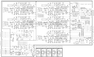
POWER SUPPLY DESCRIPTION
(Display Power Supply Block Diagram)
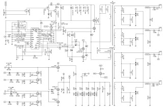
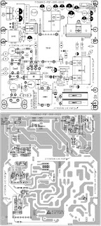
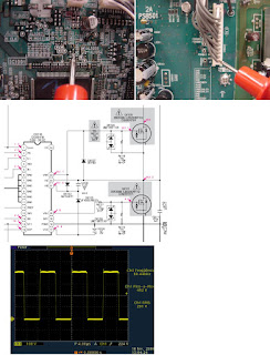
The F8 chassis family uses a free-running switch-mode power supply with a single controller IC. As AC power is applied to the set, approximately 160volts DC is developed by the bridge rectifiers and fed to the primary winding of the power transformer, then to the FET switch. The start voltage for the power supply is taken from the hot leg of the AC input. This voltage goes to controller IC 7520. A separate operating voltage is developed from the power transformer, rectified, and applied to IC 7520. The power supply is on all the time; there is no standby mode. The set is turned on and off by the microprocessor switching the +8 volt regulator on and off. The +8 volt is the supply voltage for the signal processor.
IC7520 is regulated by means of a feedback circuit, monitoring the +11 volt secondary line. Any voltage variations are reflected back to the controller IC 7520 through an Opto-Coupler IC and change the operating frequency of the power supply as needed. REMEMBER TO USE AN ISOLATION TRANSFORMER WHEN SERVICING THIS CHASSIS.
Complete Circuit Description
When AC is applied, current flow through the Bridge Rectifier circuit causes two simultaneous events to occur:
1. Capacitor 2508 begins to charge to 160 volts DC.
2. Capacitor 2540 begins to charge to 14.5 volts DC.
When capacitor 2508 is fully charged, 160 volts is applied to the drain of 7518, through transformer 5545. When capacitor 2540 is fully charged, 14.5 volts is applied to pin 1 of 7520. This voltage will cause 7520 to begin oscillating and putting out a pulse train on pin 3. These pulses will cause 7518 to conduct which will cause a field to build up in the primary winding of transformer 5545. When this field collapses, a field will be induced in the secondary windings. Pins 8 and 9 of 5545 will output to diode 6540, which will rectify the pulses. Capacitor 2540 will filter the pulses and provide approximately 12.5 volts to pin 1 of 7520. This now becomes the RUN voltage for 7520.
Feedback control is accomplished by monitoring the 140 volt line. The 140 volt, +VBATT supply is sent through resistor 3571 to pin 3 of the Programmable Regulator IC, 7570. This regulator will turn on at 2.5 volts DC. Current will then begin to flow through the diode portion of the Opto-Isolator IC, 7581. The intensity of light caused by this current flow will then control the conduction of the transistor portion of 7581. The voltage appearing on pin 4 of 7581 is then monitored by pin 14 of 7520 where it is compared to a 2.5 volt reference voltage. Changes felt on pin 14 will control the width of the pulses coming out of pin 3. These pulse changes will determine the “on” time of 7518
F8 CHASSIS INTRODUCTION
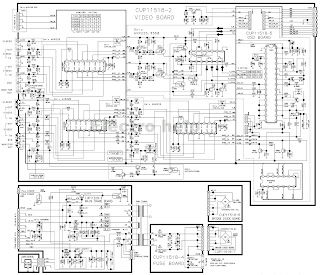
The F8 chassis is a leader TV chassis produced by Philips Consumer Electronics Company for the 1999 model year. The F8 chassis is used in sets with 25“ and 27“ screen sizes. The F8 chassis is a global design and is oriented front to rear, or ”north to south“, as it has been called. The F8 chassis tuning system features 181 channels with on-screen display (OSD). The main tuning system uses a tuner, a microcomputer IC, and a memory IC mounted on the main chassis. The microcomputer communicates with the memory IC, the customer keyboard, remote receiver, U/V tuner, signal processor IC and the audio output IC via the I2C bus. The memory IC retains the settings for favorite stations, customer-preferred settings, and service/factory data.
The F8 chassis uses a Very Large Scale (VLSI) Integrated Circuit for signal processing. This IC performs video IF, sound IF processing, AGC control, horizontal and vertical drive and synchronization, also luminance/chrominance processing. The on-screen graphics and closed caption decoding are done within the microprocessor, and then sent to the signal processor IC to be added to the main signal.
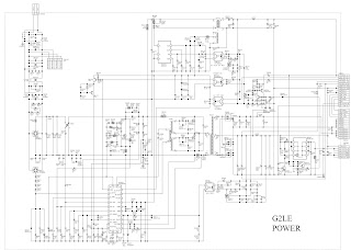
The F8 chassis utilizes a switch mode power supply for the main voltage source. The chassis has a hot chassis ground reference on the primary side of the power supply, and a cold ground reference on the secondary side of the power supply and the rest of the chassis. ALWAYS USE AN ISOLATION TRANSFORMER WHEN SERVICING THIS CHASSIS FOR YOUR SAFETY.
Vertical Circuit
The vertical drive signals are internally generated in IC7250 and are output on pins 46 and 47. From there they are sent to the Vertical Output IC, 7401, pins 1 and 7.
Inside the IC, the waveforms are amplified, shaped and output on pins 5 and 6. The output on pin 5 is the waveform that drives the yoke and provides feedback to the IC.
The output on pin 6 is the Vertical Synchronization pulse that is sent to pin 37 of the microprocessor.
Horizontal Circuit
The horizontal drive pulse is internally generated in IC7250 and is output on pin 40.
This pulse is amplified by transistor 7461 and transformer coupled by 5461 to the base of the Horizontal Output, 7460, where it is amplified.
Shaping takes place in the collector circuit (C2463 and C2465), which results in a perfectly timed 825 volt peak-to-peak pulse to drive the deflection yoke and the flyback transformer.
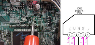
The Flyback Transformer secondary windings produce 10 working voltages:
VlotAux-11V, VlotAux+11V and VlotAux+50V all supply power to the vertical output IC, 7401.
The 187 volt VideoSupply, the filament voltage, Screen voltage (VG2) and Focus voltage all go to the CRT board.
The EHT voltage goes to the anode connection on the CRT.
The VT_Supply and the VlotAux+5V Supply both go to the Tuner. The VT_Supply is zenered down to 33 volts for tuning voltage and the VlotAux+5V supply acts as B+ for the Tuner and also becomes the +5 volt supply. The VlotAux+5V supply also provides voltage to the Audio Circuits.
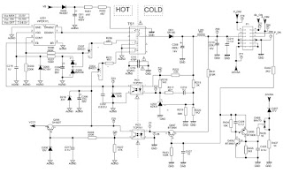
Shutdown Circuits
Three of the shutdown protection circuits are derived from pins 7 and 10 of the Flyback Transformer.
If the voltage on the filament line (pin 7) goes too low, transistor 7482 will turn on and apply a positive voltage to the P9StbyOn+Protn line.
If the voltage on the filament line (pin 7) goes too high, transistor 7462 will turn on causing transistor 7463 to turn on and apply a positive voltage to the HEW_Protn line.
If the beam current (pin 10) becomes excessive, the voltage on the EHT line will go toward the negative direction. This action will cause transistor 7481 to turn on and place a positive voltage on the P9StbyOn+Protn line.
For sets having East West correction circuitry, pin 10 of 5545 is being monitored by transistor 7470. Transistors 7470, 7481 and 7482 all control transistor 7605. In the event of a problem, 7605 will bring pin 16 of the Microprocessor, 7600 low, shutting the set down.
How to Check an Opto-Isolator
Procedure
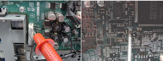
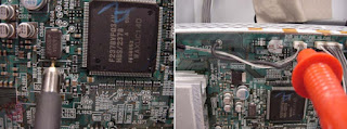
Using a basic diagram taken from the F8 schematic, we are going to determine whether or not IC7581 is functioning properly.
Step -1
Apply the positive lead of a variable DC power supply to the positive terminal of capacitor 2561. Connect the negative lead of the power supply to pin 1 of IC7570. By connecting them this way we are able to use resistors 3685 and 3575 as protection for IC7570.
Step -2
Apply the positive lead of an ohm meter to pin 5 and the negative lead to pin 4 of 7581. Set the ohmmeter to the 2K scale or greater.
Step -3
Slowly increase the DC voltage from 0 to 5 volts. If the IC is good, you will see the reading on the ohmmeter start decreasing as the voltage approaches 5 volts.
CAUTION: Do not exceed 5 volts DC.
How to Check a Programmable Regulator IC
Procedure
Using a basic diagram taken from the F8 schematic, we are going to determine whether or not IC7570 is functioning properly.
Step -1
Apply the positive lead of a variable DC power supply to pin 3 of IC7570 and the negative lead to cold (chassis) ground.
Step -2
Apply the positive lead of your DVM to pin 1 of IC7570 and the negative lead to cold ground.
Step #3-
Slowly increase the DC voltage from 0 to 2.5 volts. If the IC is good, you will begin to see a DC voltage reading on your DVM as soon as the applied DC voltage is 2.5 volts.
Service Alignment Mode (SAM)
1. The Service Alignment Mode (SAM) is used to make tuning adjustments, align the white tone, adjust the picture geometry, and make sound adjustments.
2. To enter the Service Alignment Mode (SAM), press the following key sequence on the remote control transmitter:  0-6-2-5-9-6-Status
Do not allow the display to time out between entries while keying the sequence.
SAM can also be entered by pressing the Channel Down and Volume Down keys on the local keyboard simultaneously while in SDM mode.
When Service Alignment Mode is entered, the text "SAM" will be displayed in the top right corner of the screen.
3. When Service Alignment Mode is entered, service unfriendly modes are disabled.
The following volatile SAM item values are set:
AKB = 0
VSD = 0
AFW = 275 kHz
SBL = 0
4. When the unit is operating in Service Alignment Mode, all normal on-screen displays are suppressed and replaced by a special service display. The first screen seen upon entering SAM is the ”top level SAM menu.“ The service technician must return to the top level SAM menu before exiting with a power-off command.
A sample SAM top level menu display is shown below.
Explanation of top level SAM menu display:
The Software Identification, Cluster, and Version are explained in the Service Default Mode section under ”Explanation of Display.“
The Menu Items and Sub Menus are explained below.
Note: The ”Audio“ sub menu will not be seen on screen when Service Alignment Mode is first entered. Use the Menu Up and Menu Down buttons on the remote control to view all menu items and sub menu choices.
5. To select a menu item or a sub menu in SAM, use the Menu Up or Menu Down keys on the remote control to highlight the item or menu you wish to adjust.
6. To change the value of a highlighted SAM menu item (AKB or VSD), use the Menu Left or Menu Right keys on the remote control.
7. To enter a highlighted SAM sub menu, use the Menu Left or Menu Right keys.  After entering the sub menu, use the Menu Up or Menu Down to select an item within the sub menu.
Use the Menu Left or Menu Right keys to change the value of the selected item.  Press the Menu button to return to the top level SAM menu.
8. Press the Menu button on the remote control while in SAM to switch the software to a Virtual Customer Mode; the text "SAM" will still be displayed in the upper right corner of the screen. In this mode, all customer menu adjustments to the set can be made. From the Virtual Customer Mode, press the Menu button to return to the SAM Menu.
9. Press the Status button on the remote control to toggle the OSD (except ”SAM“) ON and OFF.
10. To exit the Service Alignment Mode, turn the set off with the Power button on the remote control. To turn off the set without exiting SAM (or erasing any stored error codes), unplug the AC cord. When the set is powered on again, the Service Alignment Mode will still be active.
Note: When SAM is exited or a power interrupt occurs, the volatile SAM items AKB, VSD, AFW, and SBL will be reset to their original values.
Main Menu
The SAM main menu contains the following items:
AKB
VSD
Tuner sub menu
White Tone sub menu
Geometry sub menu
Audio sub menu
Tuner sub menu
The tuner sub menu contains the following items:
IF-PLL
AFW
AGC
YD
CL
AFA and AFB
The items AFA and AFB cannot be selected; they are for monitoring purposes only.
The item values are stored in EEPROM if this sub menu is left.
Tuner Adjustment:
AGC Takeover Point (AGC):
1. Enter the Service Alignment Mode (SAM) by pressing the following key sequence on the remote control transmitter: 0-6-2-5-9-6-Status
Do not allow the display to time out between entries while keying the sequence.
2. From the top level SAM menu, use the Menu Up/Down keys to highlight the Tuner sub menu.
3. Use the menu left/right keys to enter the Tuner sub menu.
4. In the Tuner sub menu, use the Menu Up/Down keys to highlight AGC.
5. Use the Menu Right key to raise the value of AGC until snow appears in the picture.
6. Then use the Menu Left/Right keys to reduce AGC value until the snow disappears.
a. AGC values between 10 and 20 are nominal.
b. Single digit AGC values may cause overload.
7. Upon completion of Tuner adjustment, press the Menu button to return to the top level SAM menu
White Tone sub menu
The white tone sub menu contains the following items:
Normal Red
Normal Green
Normal Blue
Delta Cool Red
Delta Cool Green
Delta Cool Blue
Delta Warm Red
Delta Warm Green
Delta Warm Blue
Note: Delta values are only used in models with the item ”Color Temperature“ in the customer menu.
OSD is kept to a minimum in this menu, in order to make white tone alignment possible.
The item values are stored in EEPROM if this sub menu is left.
The Contrast Plus feature (black stretch) is set to OFF when the White Tone sub menu is entered.
White Tone Adjustments:
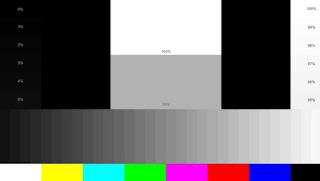
Note: The following procedure was performed with a Sencore VG91 Universal Video Generator providing grey scale bars.
1. Enter the Service Alignment Mode (SAM) by pressing the following key sequence
on the remote control transmitter: 0-6-2-5-9-6-Status.[Do not allow the display to time out between entries while keying the sequence.]
2. From the top level SAM menu, use the Menu Up/Down keys to highlight the White Tone sub menu.
3. Use the Menu Left/Right keys to enter the White Tone sub menu.
4. Set the VG91 Generator as follows: STD TV Ch. 3, RF-IF Range set to HI, RF-IF Level set to NORMAL (1), Video Pattern = Raster, R-G-B raster controls OFF.
5. Connect the RF output of the generator to the Television Antenna Input, and adjust the VG91 level to remove any snow from the raster.
6. Turn off chroma at generator and leave grey scale bars.
7. From the White Tone sub-menu, use the Menu Up/Down keys to select Normal Red, Normal Green, or Normal Blue. Then use the Menu Left/Right keys to adjust the values to obtain the best white balance.
8. A reasonable starting point for NORMAL is:
Normal Red=45, Normal Green=32, Normal Blue=39
9. After NORMAL is set, use the same method to set DELTA COOL and DELTA WARM as offsets.
A reasonable starting point for DELTA COOL is:
Delta Cool Red=(–2), Delta Cool Green=0, Delta Cool Blue=+6
A reasonable starting point for DELTA WARM is:
Delta Warm Red=+2, Delta Warm Green=0, Delta Warm Blue=(-7)
10. After the values are set, or if no changes are required, press Menu to return to the top level SAM menu.
Geometry sub menu
OSD is kept to a minimum in this sub menu in order to make picture geometry adjustments possible.
The item values are stored in EEPROM if this sub menu is left.
The value of item Service Blanking (SBL) is not stored in EEPROM, and it is set to OFF when the geometry sub menu is exited
Geometry Adjustments:
Notes:
1. The following Geometry adjustments were performed with a Sencore VG91Universal Video Generator.
2. Set the VG91 Generator as follows: STD TV Ch. 3, RF-IF Range set to HI, RF-IF  Level set to NORMAL (1), Video Pattern = Raster, R-G-B raster controls OFF,
crosshatch or center cross pattern as required.
3. Connect the RF output of the generator to the Television Antenna Input, and adjust the VG91 level to remove any snow from the raster.
Vertical Shift (VSH):
1. Enter the Service Alignment Mode (SAM) by pressing the following key sequence on the remote control transmitter: 0-6-2-5-9-6-Status
Do not allow the display to time out between entries while keying the sequence.
2. From the top level SAM menu, use the Menu Up/Down keys to highlight the Geometry sub menu.
3. Use the Menu Left/Right keys to enter the Geometry sub menu.
4. In the Geometry sub-menu, use the Menu Up/Down keys to select VAM.
5. Input a center cross pattern to the antenna/cable input terminal.
6. Using the Menu Left/Right keys, adjust VSH so that the horizontal bar is properly centered, top to bottom.
7. If other Geometry adjustments are needed, proceed to the necessary adjustment using the Menu Up/Down buttons.
8. Upon completion of Geometry adjustments, press the Menu button to return to the top level SAM menu.
Vertical Amplitude (VAM):
1. Enter the Service Alignment Mode (SAM) by pressing the following key sequence on the remote control transmitter: 0-6-2-5-9-6-Status
Do not allow the display to time out between entries while keying the sequence.
2. From the top level SAM menu, use the Menu Up/Down keys to highlight the Geometry sub menu.
3. Use the Menu Left/Right keys to enter the Geometry sub menu.
4. In the Geometry sub-menu, use the Menu Up/Down keys to select VAM.
5. Input a crosshatch pattern to the antenna/cable input terminal.
6. Using the Menu Left button, reduce the value so that the picture does not fill the entire screen.
7. Use the Menu Up/Down keys to select VSH (Vertical Shift) from the Geometry sub-menu and, using the Menu Left/Right keys, center the picture on the screen, top to bottom.
8. Using the cursor up/down keys, select VAM from the Geometry sub-menu, and use the Menu Right key to increase the value to obtain a slight over scan.
9. If other Geometry adjustments are needed, proceed to the necessary adjustment using the Menu Up/Down buttons.
10. Upon completion of Geometry adjustments, press the Menu button to return to the top level SAM menu.
Horizontal Shift (HSH):
Note: This adjustment centers the video on the raster. It does not move the raster.
1. Enter the Service Alignment Mode (SAM) by pressing the following key sequence on the remote control transmitter: 0-6-2-5-9-6-Status
Do not allow the display to time out between entries while keying the sequence.
2. From the top level SAM menu, use the Menu Up/Down keys to highlight the Geometry sub menu.
3. Use the Menu Left/Right keys to enter the Geometry sub menu.
4. In the Geometry sub-menu, use the Menu Up/Down keys to select HSH.
5. Input a center cross pattern to the antenna/cable input terminal.
6. Using the Menu Left/Right keys, adjust HSH so that the vertical bar is properly centered, left to right.
7. If other Geometry adjustments are needed, proceed to the necessary adjustment using the Menu Up/Down keys.
8. Upon completion of Geometry adjustments, press the Menu button to return to the top level SAM menu.
Vertical Slope (VSL):
1. Enter the Service Alignment Mode (SAM) by pressing the following key sequence on the remote control transmitter: 0-6-2-5-9-6-Status
Do not allow the display to time out between entries while keying the sequence.
2. From the top level SAM menu, use the Menu Up/Down keys to highlight the Geometry sub menu.
3. Use the Menu Left/Right keys to enter the Geometry sub menu.
4. In the Geometry sub-menu, use the Menu Up/Down keys to select VSL.
5. Input a crosshatch pattern to the antenna/cable input terminal.
6. Using the Menu Left/Right keys, adjust VSL so that the squares at the bottom of the screen are equal in size to the squares at the top of the screen.
7. If other Geometry adjustments are needed, proceed to the necessary adjustment using the Menu Up/Down keys.
8. Upon completion of Geometry adjustments, press the Menu button to return to the top level SAM menu.
Vertical S-Correction (VSC):
1. Enter the Service Alignment Mode (SAM) by pressing the following key sequence on the remote control transmitter: 0-6-2-5-9-6-Status
Do not allow the display to time out between entries while keying the sequence.
2. From the top level SAM menu, use the Menu Up/Down keys to highlight the Geometry sub menu.
3. Use the Menu Left/Right keys to enter the Geometry sub menu.
4. In the Geometry sub-menu, use the Menu Up/Down keys to select VSC.
5. Input a crosshatch pattern to the antenna/cable input terminal.
6. Using the Menu Left/Right keys, adjust VSC so that the squares at the center of the screen are equal in size to the squares at the top and bottom of the screen.
7. If other Geometry adjustments are needed, proceed to the necessary adjustment using the Menu Up/Down keys.
8. Upon completion of Geometry adjustments, press the Menu button to return to the top level SAM menu.
Service Blanking (SBL):
Service Blanking provides a straight cutoff line in the center of the raster. It is useful when centering the raster. It can also be used in adjusting the yoke and setting vertical size and linearity.
1. Enter the Service Alignment Mode (SAM) by pressing the following key sequence on the remote control transmitter: 0-6-2-5-9-6-Status
Do not allow the display to time out between entries while keying the sequence.
2. From the top level SAM menu, use the Menu Up/Down keys to highlight the Geometry sub menu.
3. Use the Menu Left/Right keys to enter the Geometry sub menu.
4. In the Geometry sub-menu, use the Menu Up/Down keys to select SBL.
5. Use the Menu Left/Right keys to toggle SBL ON or OFF.
6. With SBL on, VSH can be used to center the raster on the fiduciary marks (the small notches in the phosphor on the right and left edge of the CRT). These are absolute center.
7. If other Geometry adjustments are needed, proceed to the necessary adjustment using the Menu Up/Down keys.
8. Upon completion of Geometry adjustments, press the Menu button to return to the top level SAM menu.
Delta HSH for 60Hz (H60):
Note: This adjustment should not be changed from the factory preset value (10).
Delta VAM for 60Hz (V60):
Note: This adjustment should not be changed from the factory preset value (5).
Note: The following GEOMETRY adjustments can only be performed on models containing an East-West Panel (Diode Modulator).
East-West Width (EWW):
1. Enter the Service Alignment Mode (SAM) by pressing the following key sequence on the remote control transmitter: 0-6-2-5-9-6-Status
Do not allow the display to time out between entries while keying the sequence.
2. From the top level SAM menu, use the Menu Up/Down keys to highlight the Geometry sub menu.
3. Use the Menu Left/Right keys to enter the Geometry sub menu.
4. In the Geometry sub menu, use the Menu Up/Down keys to select EWW.
5. Input a crosshatch pattern to the antenna/cable input terminal.
6. Use the Menu Left key to reduce the value of EWW so that the picture does not fill the entire screen.
7. Use the Menu Up/Down keys to select HSH (Horizontal Shift) from the Geometry sub menu and, using the Menu Left/Right keys, center the picture on the screen.
8. Use the Menu Up/Down keys to select EWW from the Geometry sub menu, and use the Menu Right key to increase the value to obtain a slight overscan.
Note: Remember, adjusting EWW will affect other horizontal adjustments.
9. If other Geometry adjustments are needed, proceed to the necessary adjustment using the Menu Up/Down keys.
10. Upon completion of Geometry adjustments, press the Menu button to return to the top level SAM menu.
East-West Parabola/Width (EWP):
1. Enter the Service Alignment Mode (SAM) by pressing the following key sequence on the remote control transmitter: 0-6-2-5-9-6-Status
Do not allow the display to time out between entries while keying the sequence.
2. From the top level SAM menu, use the Menu Up/Down keys to highlight the Geometry sub menu.
3. Use the Menu Left/Right keys to enter the Geometry sub menu.
4. In the Geometry sub menu, use the Menu Up/Down keys to select EWP.
5. Input a crosshatch pattern to the antenna/cable input terminal.
6. Use the Menu Left/Right keys to adjust the value of EWP.
7. This adjusts the top and bottom of the right and left side of the raster, adjusting the raster by “bending” it out or in.
8. This adjustment should be set so that the screen appears to be straight and “flat.”
9. If other Geometry adjustments are needed, proceed to the necessary adjustment using the Menu Up/Down keys.
10. Upon completion of Geometry adjustments, press the Menu button to return to the top level SAM menu.
East-West Trapezium (EWT):
Enter the Service Alignment Mode (SAM) by pressing the following key sequence on the remote control transmitter: 0-6-2-5-9-6-Status
Do not allow the display to time out between entries while keying the sequence.
2. From the top level SAM menu, use the Menu Up/Down keys to highlight the Geometry sub menu.
3. Use the Menu Left/Right keys to enter the Geometry sub menu.
4. In the Geometry sub menu, use the Menu Up/Down keys to select EWT.
5. Input a crosshatch pattern to the antenna/cable input terminal.
6. Use the Menu Left/Right keys to adjust the value of EWT.
7. This balances the width at the top of the screen to the width at the bottom of the screen.
8. This adjustment should be set so the top and bottom of the screen are of equal width.
9. If other Geometry adjustments are needed, proceed to the necessary adjustment using the Menu Up/Down keys.
10. Upon completion of Geometry adjustments, press the Menu button to return to the top level SAM menu.
East-West Corner Parabola (EWC):
1. Enter the Service Alignment Mode (SAM) by pressing the following key sequence on the remote control transmitter: 0-6-2-5-9-6-Status
Do not allow the display to time out between entries while keying the sequence.
2. From the top level SAM menu, use the Menu Up/Down keys to highlight the Geometry sub menu.
3. Use the Menu Left/Right keys to enter the Geometry sub menu.
4. In the Geometry sub menu, use the Menu Up/Down keys to select EWC.
5. Input a crosshatch pattern to the antenna/cable input terminal.
6. Use the Menu Left/Right keys to adjust the value of EW CORNER.
7. This adjustment affects the very corner sections of the raster, and acts as a “touch-up” of the EWP (East-West Parabola/Width) adjustment.
8. This adjustment should be set so the corners of the screen are straight and equal in size.
9. If other Geometry adjustments are needed, proceed to the necessary adjustment using the Menu Up/Down keys.
10. Upon completion of Geometry adjustments, press the Menu button to return to the top level SAM menu.
Audio sub menu
The audio sub menu item values are stored in EEPROM if this sub menu is left.
Attack Time at AVL (AT):
1. Enter the Service Alignment Mode (SAM) by pressing the following key sequence on the remote control transmitter: 0-6-2-5-9-6-Status
Do not allow the display to time out between entries while keying the sequence.
2. From the top level SAM menu, use the Menu Up/Down keys to highlight the Audio sub menu.
3. Use the Menu Left/Right keys to enter the Audio sub menu.
4. Use the Menu Left/Right keys to adjust the value of AT.
5. Set the volume of AT to 4.
6. Upon completion of Audio adjustment, press the Menu button to return to the top level SAM menu.
Convergence and Purity Adjustments
Notes:
1. The following adjustments were performed with a Sencore VG91 Universal Video Generator.
2. Set the VG91 Generator as follows: STD TV Ch. 3, RF-IF Range set to HI, RF-IF Level set to NORMAL (1), Video Pattern = Raster, R-G-B raster controls OFF, Mode Switch set to L+R, Audio Frequency set to 300Hz, and 0 Pilot (max. CCW).
3. Connect the RF output of the generator to the Television Antenna Input, and adjust the VG91 level to remove any snow from the raster.
Pre-Convergence Procedure
Note: The degaussing procedure should be performed prior to this adjustment.
1. Place the multi-pole Purity and Convergence Assembly with the 2-Y pole purity rings directly in the gap between the G2 and G3 (focus) grids as shown in the "Convergence and Purity Assembly" graphic.
2. Enter Service Alignment Mode (refer to Service Alignment Mode section).
3. Apply a center cross or crosshatch pattern to the antenna/cable input terminal.
4. Select the White Tone sub-menu by pressing the Menu Up/Down keys on the remote control so that White Tone is highlighted.
5. Use the Menu Left/Right keys to enter the White Tone sub-menu.
6. Use Menu Up/Down keys to toggle between the options. Be sure to record the values of all options (Normal Red/Green/Blue, Delta Cool Red/Green/Blue, and Delta Warm  Red/Green/Blue).
7. Use the Menu Up/Down keys to select Normal Green, and use the Menu Left key to set Normal Green to minimum.
8. Loosen the yoke clamp screw, pull the yoke back, and remove the three yoke wedges.
9. Slide the yoke all the way forward so that it rests against the bell of the CRT.
10 Tighten the yoke clamp screw so that the yoke does not drop away from the bell of the CRT.
11. Slowly spread, and if necessary, rotate the 2-Y pole purity rings so that the red and blue lines are at least parallel and preferably coincide at the 6:00 and 12:00 positions as shown in the "2Y Spread and 2Y Rotate" graphic.
12. Proceed to the Color Purity Adjustment
Color Purity Adjustment
1. Connect a solid white pattern signal to the antenna/cable input terminal.
2. Use the Menu Up/Down keys to select Normal Blue, and use the Menu Left key to set Normal Blue to minimum.
3. Use the Menu Up/Down keys to select Normal Red, and use the Menu Right key to set Normal Red to maximum.
4. Slowly spread the 2-X pole purity rings to center the red portion of the screen, leaving the same amount of green on one side of the screen as blue on the other side.
5. Tighten the yoke clamp screw slightly so that the yoke may be moved with some friction.
6. Proceed to the Static Center Convergence Adjustment.
Static Center Convergence Adjustment
1. Apply a center cross or crosshatch pattern to the antenna/cable input terminal and observe the screen to ensure that the yoke is not tilted. If necessary, rotate the yoke to obtain a level raster.
2. Use the Menu Up/Down keys to select Normal Blue, and use the Menu Right key to set Normal Blue to maximum.
3. Slowly spread, and if necessary, rotate the 4-pole magnetic rings to converge red and blue lines at the center of the screen.
4. Use the Menu Up/Down keys to select Normal Green, and use the Menu Right key to set Normal Green to maximum.
5. Slowly spread, and if necessary, rotate the 6-pole magnetic rings to converge red/blue on green lines at the center of the screen.
6. Repeat steps three and five for optimum performance.
7. Proce (Display Convergence and Purity Assembly)
Dynamic Edge Convergence Adjustment
Note: To secure the correct position of the deflection yoke, three rubber wedges are used. 
1. Apply a crosshatch pattern to the antenna/cable input terminal.
2. Use the Menu Up/Down keys to select Normal Green, and use the Menu Left key to set Normal Green to minimum.
3. Tilt the yoke up and down to converge the red and blue vertical lines at the 6:00 and 12:00 positions and the red and blue horizontal lines at the 3:00 and 9:00 positions (refer to Figure 5 ). When the correct position has been found, place a rubber wedge between the yoke and the CRT. If the yoke is tilted up, place wedge one as shown in Figure 3a; if it is tilted down, place wedge one.
4. Tilt the yoke to the left and right to find the point of best possible convergence of the red and blue lines at the edges, top and bottom of the screen.
6. When the correct position is located, place wedges two and three.
5. Remove wedge one and place it in the final position.
6. Use the Menu Up/Down keys to select Normal Green, and use the Menu Right key to set Normal Green to maximum.
7. Proceed to the White Balance Setup.
Master Screen (VG2)/ White Balance Setup:
1. With the set OFF, rotate VG2 (located on the lower part of the flyback transformer) counterclockwise.
2. Use the Power Button (on the remote control or the local keyboard) to turn the set ON, without a signal, and rotate VG2 clockwise until snow is visible.
3. Enter Service Alignment Mode (refer to Service Alignment Mode section).
4. Enter the Virtual Customer Menu by pressing the Menu button on the remote and set brightness and picture to 31 and color to 0.
5. Apply an NTSC color bar signal to the antenna/cable input terminal and tune to the active channel.
6. Connect an oscilloscope, 20V per division and 10 uSec time base, to pin 6 of the CRT Socket. Observe the stairstep pattern while adjusting VG2.
Hint: Counterclockwise adjustment will compress bottom of stairstep pattern.
Clockwise adjustment will compress top of stairstep pattern.
7. Adjust VG2 midway between top and bottom compression.
8. Proceed to White-Tone Adjustments under White Tone sub-menu in the Service Alignment Mode section to complete White Balance Setup.

Customer Service Mode (CSM)
1. The Customer Service Mode (CSM) is used to retrieve data on the TV operation settings and stored error codes.
2. To enter the Customer Service Mode, press and hold the Mute button on the remote control and any key on the local keyboard (except ”Power“) for more than 4 seconds. When the set is in Customer Service Mode, the text "CSM" is displayed in the top right corner of the screen.
3. To use this system, the customer is instructed by phone to enter CSM and read off the display that appears. This information is useful to gain insights into failures before traveling to the customer's home.
4. This information can also be used to avoid nuisance trips to the home when the problem is an operational error (example: Closed Caption is on or set is in Hospital Mode).
5. When entering CSM, all disruptive functions are turned off, and service unfriendly modes are ignored. While CSM is active, no changes can be made in settings or functions. When CSM is exited, the TV returns to all prior operational settings.
6. To exit CSM, press any key (on the remote control or local keyboard) except ”Channel Up“ or ”Channel Down.“
To exit CSM and return the set to normal operation mode, press any key on the local keyboard or the remote control except Channel Up, Channel Down, or Power.
To exit CSM and turn the set off, press the Power button on either the TV set or
the remote control.
Explanation of CSM Display Screen
The following information is displayed on screen:
• Text ”CSM“ on the first line
• Line number for every line (to make CSM language independent)
• To view multiple CSM pages (such as lines 8 and 9), use the Channel Up or Channel Down keys
• For more information on lines 1, 2, and 3, see SDM section ”Explanation of Display“
• Line 1 displays the run timer and the software identification, cluster, and version
• Line 2 displays the error buffer contents (the word ”error“ is not used on this screen, instead ”codes“ is used)
• Line 3 displays the option code information
• Line 4 displays SYS: (This is not used)
• Lines 5 through 8 display information on active service unfriendly modes
• Line 5 displays the text ”NOT TUNED“ if no television station is tuned
• Line 6 displays the text ”TIMER“ if the sleep timer or ”on“ timer is active
• Line 7 displays the text ”LOCKED“ if one or more channels or presets is locked via child lock
• Line 8 displays the text ”HOSPITAL“ if hospital mode is active, or ”HOTEL“ if hotel mode is active
• If the volume limiter is active, line 9 displays the text ”VOL LIM“ and the set value of the volume limiter. If the volume limiter is inactive, the displayed value will be 255 (the maximum volume allowed)


AOC L42H961 – 42 inch LCD TV – password lock, factory mode (Service mode), SMPS and Back-light inverter schematic, troubleshooting

$
0
0
Password Setting: Change the 4-numeral parental control password.
Three steps are required for changing the password:
Enter Old Password > Enter New Password > Confirm New Password.
Note: This item is only available in TV, Composite and S-Video source modes.
The default password is 0 0 0 0 .
Parental Control: provide the parental Control (V-chip) function setting. Before entering the Parental Control sub-menu, user has to key in the password first. Enter the Parental Locks item, then the user can modify the restricted table about MPAA or TV Rating respectively. While exiting the sub-menu, the parental control function is working. The inhibitive channels or source signals can be un-lock through pressing the V-CHIP key on the remote control and then key in the correct password. Note: This feature is only available in TV, Composite and S-Video source modes. (The default password is: 0 0 0 0.)
Button Lock– Select On or Off to lock or unlock the control buttons on the side panel of the TV. When this function enables, the control buttons on your TV will be locked and TV will be controlled by remote control only.
Block Unrated TV– When Block Unrated TV is set to on, your TV will block unrated program.
USA Parental Locks– Set the parental control level by MPAA or TV Rating.
Canadian Parental Locks– Set the parental control level by English Rating or French Rating.
Open V-Chip – Open V-Chip is an advanced V-Chip rating system for digital channels that are received.
The rating table will be updated by downloading the RRT5 data for blocking.
Factory mode (service mode)
In the TV mode adjust volume to zero, press menu key and then press number key 1 - 9 - 9 - 9.
It will achieve the factory mode.
Press the “Exit” button on remote control to quit from factory mode.
Quick troubleshooting
Abnormal display
Can't start
No display
No Power
Power (SMPS) board 715G3351-H  - Circuit diagram (Schematic) AOC L42H9651
 Inverter Board 715G3358 schematic - AOC L42H961
For HDTV Set-Top Boxes with DVI
1. Turn off the HDTV and HDTV Set-Top Box.
2. Using a HDMI-DVI cable, connect the DVI end to your HDTV Set-Top Box and the HDMI end to the HDMI Input at the rear of the HDTV.
3. Turn on the HDTV and HDTV Set-Top Box.
4. Select HDMI using the SOURCE button on the remote, side of the HDTV, or directly by pressing the HDMI/PC button on the Remote Control.
Connecting your HDTV Set-Top Box (Better)
1. Turn off the HDTV and HDTV Set-Top Box
2. Connect the Pr (red color) connector on your HDTV Set-Top Box to the corresponding Pr (red color) connector in the Component group.
3. Connect the Pb (blue color) connector on your HDTV Set-Top Box to the corresponding Pb (blue color) connector in the Component group.
4. Connect the Y (green color) connector on your HDTV Set-Top Box to the corresponding Y (green color) connector in the Component group.
5. Using an audio cable (red and white connectors), connect the cable to the audio output connectors associated with the Component output on your HDTV Set-Top Box and connect the other end to the audio connectors associated with the Component.
6. Turn on the HDTV and HDTV Set-Top Box.
7. Select Component using the SOURCE button on the remote, side of the HDTV or directly by pressing the COMP button on the Remote Control.
Using Component Video
Connecting your DVD Player (Better)
1. Turn off the HDTV and DVD player.
2. Connect the Pr (red color) connector on your DVD player to the corresponding Pr (red color) connector in the Component at the rear of the HDTV.
3. Connect the Pb (blue color) connector on your DVD player to the corresponding Pb (blue color) connector in the Component group at the rear of the HDTV.
4. Connect the Y (green color) connector on your DVD player to the corresponding Y (green color) connector in the Component group at the rear of the HDTV.
5. Using an audio cable (red and white connectors), connect the cable to the audio output connectors associated with the Component output on your DVD player and connect the other end to the audio connectors associated with the Component input at the rear of the HDTV.
6. Turn on the HDTV and DVD player.
7. Select Component using the SOURCE button on the remote, side of the HDTV or directly by pressing the COMP button on the Remote Control.
Connecting Your VCR or Video Camera
1. Turn off the HDTV and VCR or Video Camera.
2. Connect the S-Video jack on the rear of your VCR or Video Camera to the S-Video jack in the AV group on the rear of the HDTV.
3. Connect an audio cable (white and red connectors) cable to the audio output connectors associated with the S-Video output on your VCR or Video Camera and connect the other end to the audio connectors associated with the AV input on the rear of the HDTV.
4. Turn on the HDTV and VCR or Video Camera.
5. Select AV using the SOURCE button on the remote, side of the HDTV or directly by pressing the VIDEO button on the Remote Control.
Connecting to a PC
1. Turn off the HDTV and PC.
2. Connect a 15-pin D-Sub RGB (VGA) cable to the RGB output of your PC and the other end to the VGA input at the rear of the HDTV.
3. Connect the Audio Out on your computer to the AUDIO input at the rear of the HDTV.
4. Turn on the HDTV and PC.
5. Select VGA using the SOURCE button on the remote, side of the HDTV or directly by pressing the HDMI/PC button on the Remote.

Philips LCD TV 24PFL5505 (MS19C) Service mode, software update, SMPS schematic

$
0
0
Applicable to: Philips24PFL4505, Philips32PFL4305, Philips32PFL3305, Philips42PFL3505 LCD TVs
Service Procedure
MS19C-AP is the latest design especially for LCDTV products selling in India market.
It features by its high integration, easy debugging as well as convenience in terms of maintenance. Fast software upgrade through USB disk facilitates both manufacture and after service
Design Menu accessing way
In the first place, press Menu button of remote control, then select Contrast item of Picture submenu.
Finally, press 1, 9, 5, 0 consecutively
Press the Up/Dn button in remote control to select certain item and Left/Right to toggle among or execute the available options.
DESIGN HOTKEY
When the DESIGN HOTKEY item of Design Menu is enabled [ON], press A/CH button of remote control can access DESIGN MENU quickly
[HOTKEY is use for Quick Access of Design Menu]
SHOP INIT (SHOP MENU)
Contain many options which can be chosen according to the requirements of customers as default settings when leave factory.
Press the Up/Dn button in remote control to select certain item and Left /Right to toggle among the available options.
SOUND SETTING
In sound setting you can set sound parameter to satisfy your standard.
Sound mode including STEREO, MUSIC, NEWS, PERSONAL.
In each mode there are five EQ parameters. You can set the frequency band parameters. After the changing parameters, comes out from the Design Mode. The new setting will be available for the Customer.
You can also change the USB SOUND MODE parameters.
The SUBVOLUME is plus of Main VOLUME, the default numerical is ZERO (0)
[do not change the SUBVOLUME default value.]
LANGUAGE SETTING
In Language Setting, there are seven (7) languages available for customer selection. You can set it to ON if you need any language. After exiting from Design Menu, you can access the available language in "FUNCTION" item of User Menu.
The default language in Language Setting is ENGLISH.
[Please do not change language setting other than ENGLISH]
Software upgrade
Method 1
1) Please ensure the software you are using has a correct file name (If the resolution of panel is 1920*1080, the name should be TCL_MS19C_UPDATE_FHD.bin, if resolution is 1366*768, file name should be TCL_MS19C_UPDATE.bin), copy it to the root directory of USB disk.
2) Insert the USB disk to the USB socket of the setDŽ
3) Press Menu button of remote control, and select Contrast item of Picture submenu, then press 1,9,5,0 consecutively, there you go the DESIGN MENU.
4) In DESIGN MENU, Go to the FACTORY MENU,select USB UPDTE item and press the right button of remote control to start upgrade
5˅ When prompt of “Update finished” show on the screen, please do AC Power ON/OFF.
6) Enter the DESIGN Menu,then FACTORY MENU again, and check the software information (Version/Date/Product model) at the bottom of menu. If the project name is not the one you wanted, you are recommended to change the Project ID as per following "Project ID selecting" procedure.
Method 2
1) Please ensure the software file have correct file name (Refer to Method 1), copy it to the root directory of USB disk.
2) Insert the USB disk to the USB socket of the set
3) Press CH- button on key board and AC switch on the set at the same time. Wait for
10 seconds then release the CH- button to start upgrade
4˅ When prompt of “Update finished” show on the screen, please do AC Power ON/OFF.
[use Method 1 to upgrade if the set can work properly. In some circumstances, such as no picture, Method 2 could be an alternative. During the upgrade procedure, power supply cannot be cut off.]
Project ID selecting
1) Press Menu button of remote control, then select Contrast item of Picture submenu; press 1,9,5,0 consecutively, there you go the DESIGN MENU.
2) Select the SERVICE MENU item, press OK or RIGHT button of the remote to enter the submenu;
3) Select the PROJECT ID item, press OK or RIGHT button of the remote to enter the submenu;
4) Press RIGHT or LEFT button of the remote to select the ID you want.
5) After ID selection, press MENU button of the remote to exit DESIGN MENU.
6) Finally, do AC POWER ON/OFF.
Voltage chart
Click on the pictures to magnify
Power part
SMPS

Konka and Thomson KIP L145E06C2-01 SMPS schematic

$
0
0
Used ICs: FSGM300, FAN7530, WFW20N50[SMPS FET], FSFR1700, LM324  

Click on the pictures to zoom in


TCL and Thomson - L32B2810/MT31BP-AP – Alignment procedure - how to upgrades the software – detailed description

$
0
0
Alignment Procedure - MM31BP Series
These chassis are designed for European LCD TV markets with MPEG4 for both TCL/THOMSON brands. The main chip is from Mediatek (MT5531 series)
MT5531 FLASH Size and Key Blocks Location’s Assignment – MT31BP-AP (V0 91).DOCX
To communicate with the TV product for debugging, adjustments and so, it is required suitable 0-5V serial Interface like in the following picture
Pre-Conditions and DC/DC Check
Before power on, please check the board according to the relevant block diagram and circuit diagram, and make sure that no serious issue or mistake can destroy the board. For example, the output of DC/DC and LDO should not be shorted to ground.
Supply a suited voltage and power-on, then check the voltage according to the relevant block diagram, circuit diagram and voltage specification within 5% margin.
For example, check SoC voltage (AV3V3, VCCK-1V2, etc.), DDR voltage (DDRV) , amplifier voltage (Main_Power), etc… Only the standby voltage is necessary if there is no software in the flash.
SW Image download
Download the latest release SW from below FTP server:
- Link:xxxxx
- Username: xxxxx
- Password: xxxxx
- Folder: xxxxx
OAD Transport Stream Image
To manage quicker mass reflashing, a predefined OAD DVB-T channel (freq:850MHz / bandwidth:8MHz) is embedded to SW core and only available into Factory mode. Some licensed IBL tools ('xxx2lli.exe', 'lli2dsm.exe', dsmmerge.exe, …) from Intellbyte Inc. http://www.intellibyte.com/ might be necessary to create appropriate DVB SSU TS. Over some predefine settings such as repeated datablock insertion, null packets size, … (controllable in configuration file), here below are mandatory OUI entries structure to prepare DSM-CC carousel image format:
 [SW Entry are referring to following PKG image file name “V8-0MT310x-LF1Vyyy.pkg”
 See enclosed necessary Data Broadcast Carousel configuration file format details (DBC)]
To build an OAD TS, it’s necessary to create a temporary common and interchangeable DSM file format using below command and arguments:
‘bin2dsm.exe -v -v -v -m0,0,"TCL_HW5881",0 -n200 -z102400 -nz -o%FILE%.dsm -h"OUI=CUST_OAD_OUI
model=CUST_OAD_HW_MODEL version=CUST_OAD_HW_VERSION vm=0xffff" -s"OUI=CUST_OAD_OUI
model=CUST_OAD_SW_MODEL version=CUST_OAD_SW_VERSION vm=0xffff" %FILE%.pkg’
Then, OAD TS can be completed using below command and arguments:
‘dsmsectn.exe -v -dvbssu -mpegts -patpmt -nit_ter -sdt -o%FILE%.ts -gTCL_HW5881.dbc %FILE%.dsm’
For more robustness, TS can be played with following presets such as modulation:QAM-64, guard interval:1/8, coding rate:2/3 to ensure ~22Mbps.
OAD reflashing process is managed within 4 steps operation: multiplex detection, DVB transfer, flashing and warm-start.
UART & IR Parser
To use both UART and/or IR parser, TV has to be set in Factory mode with its VGA port well connected to suitable UART device or an IR emitter device correctly facing up TV (see below “Product Assembly - section 2.0”
How to activate “Factory key”).
The SoC’s RS232 mode is automatically enabled at power-on and doesn’t require any command initialization frame. <0x30 0x30 0x30 0x2E 0x30 0x65 0x30 0x74 0x30 0x0D 0xE2> from host to TV.
So correctly setup UART parser engine for further serial communication, it’s necessary to send following command frame <0xAA 0x06 0x10 0x01 0xA7 0xEF> within following COM presets 115200/8/n/1; “PS” caption might be toggled and displayed on bottom left screen (“S” like Serial) if successful.
To communicate with TV depending on SIACP revision layout implementation, you may need to fulfill UART/IR commands protocol and format described on enclosed SIACP requirements document.
Project ID Modification
There are different IDs stored into system memory depending on different Panels settings and Models features, but there’s only one key branching ProjectID that includes all. So, it’s not recommended to modify PaneID with 
Hyper terminal as other ID features may not change.
To modify ProjectID, you need to go through “Factory menuOtherProject infoProject ID”, then spin left or right with RCU “◄/►” key” keys to suitable ID (Project name is dynamically refreshed).
Below is none exhaustive Project ID table for reference. Project list and all relative information are dispatched and updated as a new firmware package is released.
32T3520 配 MT31BP 项目 109 PANEL_CS2_ST3151A04
32B2800 配 MT31BP 项目 110 PANEL_CS2_ST3151A04
32B2610S 配 MT31BP 项目 111 PANEL_CS2_ST3151A04
32B2600 配 MT31BP 项目 108 PANEL_CS2_ST3151A04
23E4200 MT31BP 项目 113 PANEL_SS_LSC230AN0
24T3520 MT31BP 项目 114 PANEL_AUO_M240HTN01
24B2500
MT31BP 项目 115 PANEL_CM5_V236BJ1_P03
28T3520
MT31BP 项目 116 PANEL_CS5_ST2751A01
28B2500B
MT31BP 项目 107 PANEL_CS5_ST2751A01
24B2800
MT31BP 项目 117 PANEL_CM1_ V236BJ1_LE2
32T3520
MT31BP 项目 109 PANEL_CS2_ST3151A04
Once the boards (chassis, KB, IR, PSU…) and the panel are well interconnected, plug all suitable signals generator to relevant below inputs/outputs using respective test patterns format to check picture/sound quality.

Picture/Video formats and Audio tones can be changed by the factory according to their own standard and broadcasted signals (ie: 1KHz & 3KHz, sweep, …
DDC & EDID & T-Link Test
The E-EDID data structures are according to VESA Enhanced EDID 1.4a (and EIA/CEA-861B for HDMI)..
All VGA and HDMI structures have their own BIN profile which are part of firmware and uploaded at power-on.
For EDID check, it’s recommended to check whether the correct EDID is uploaded by checking corresponding EDID NVM Checksum or read them out to check bit by bit if it is in line with the released EDID bin file.
HDCP Upgrade and Test
For HDCP compliancy, it’s needed to check whether the HDCP key has been well set by connecting suitable generator signal.
IP Return Test
How to upgrade MAC address using USB
All MT31 series platform support IP return function according to CI+ v1.3.
Here is some representative code example: 40-8B-F6-90-4D-53
Factory Menu
Follow the below steps to pop-up the Factory menu in case of “FactoryKey” is disabled:
- Press RCU “MENU” key to display main menu
- Select “Picture” and press “OK” key to enter into Picture submenu
- Scroll down to “Contrast” item
- Press the subsequence RCU keys “9”, “7”, “3” and “5”
In case of “FactoryKey” is enabled, just press RCU “Return” key to pop-up again the Factory menu.
The status of “Factory Key” can be changed in “Factory Menu->Hotkey”
Press RCU “OK/►” key to enter the submenu.
Press RCU “Menu” key to go back to the root menu.
Press RCU “◄/►” key to change the values.
Press RCU “OK” key run the function.
Press RCU “Exit” keyto exit the Factory menu.
While “FactoryKey” is enabled, there’re some toggled display informations (~2s) relative to SW, ProjectID, CI+, NetworkID to facilitate 100% quick screening without accessing to whatever else menu.
Channel Map Preset
Region channel Maps are stored in the firmware and can be directly preloaded via Factory menu.
Other faster methods via UART/IR commands are available on enclosed SIACP requirements.
Warm-up Test
Following TCL standard and practices, it’s required minimum 15min of Warm-Up that can be considered as Burn-In. Additional Aging for White Balance alignment is no more necessary due to consistent Picture Performance with Cloning usage.
This function is accessible by selecting “Factory menu
èBurning Mode”, pressing RCU “OK/►” key, to release/disable Burn-in mode, it’s just required to press “Menu” button from local keyboard. Other faster methods via UART/IR commands are available on enclosed SIACP requirements.
White Balance Touch-Up (Golden sample)
As some color coordinates discrepancies can be noticed from panel batches to others, it may necessary to perform slight touch-up.
For Color temperature adjustment, switch TV on leading HDMI input where should be connected suitable generator providing following format 1280x720p@60Hz test pattern. A 32 steps grey scale is recommended to assess relevant calorimetric tracking and low/high light saturation points.
Make sure Picture Preset is set to “DYNAMIC” mode, both “Contrast” and “Backlight” bargraph are set to “100” (maximum), “Gamma” bar graph are set to “0” (2.2 nominal) and that both “Energy Saving” and “Light Sensor” are set to “Off” from “ECO Settings” subsection.
Ensure that TV is in Factory mode to access to ”White Balance” adjustment submenu, then scroll down to toggle off “Pic. Enhance” flag.
PC VGA, CMP YPrPb, SCART RGB, CVBS_PAL/SECAM Gain/Offset matrix offsets locations are relative to HDMI/DTV.
Warm and Cool Tone are relatives to Normal mode. WB adjust need to fix default G Gain .
>  “Gain” registers set need to be adjusted at 70IRE.
>  “Offsets” registers set can be adjusted at 30IRE, but it’s not recommended to keep them defaulted.
Note: All matrix offsets locations can be individually fine-tuned.
Targets and Tolerances for all inputs
Note: The White balance value is right conformed by PQ Engineer , Except PQ Engineer, anybody can not change the white balance value and Default value.
The measured and adjustable parameters should be mainly “x”, “y” coordinates (see “TCL EU Picture Quality Requirements for FPDs” for reference).
The signal level check has been down in R&D, Factory should not adjust the scaling Brightness , scaling contrast and scaling saturation.
The White Balance alignment should be performed using a well calibrated and contact less analyzer (ex: CA310). The analyzer may not touch the screen surface, and measurement must be performed in a dark environment keeping the probe(s) at 90+/-2° from the panel center.
(The results should fulfill following TCL matching requirements (Minolta CA210-CH00 based):
Cloning
To operate master/golden clone and reuse it further on demand, please to follow below Cloning SOP: Cloning Procedure for MT5531 Series (v1
All underused BIN image files need to be used strictly with MT5531 SoC platform as depending on SW structure.
Other faster access methods via UART/IR commands are available on enclosed SIACP requirements.
SHOP-END Test
At final process stage, it’s necessary to perform “Reset shop” before any packing to leave Factory mode and restore User default presets
This function is accessible by selecting “Factory menu ÆReset Shop”, then pressing RCU “OK/►” key. Other faster methods via UART/IR commands are available on enclosed SIACP requirements.
“Reset Shop” presets should follow “MT5531_EU_OOB_MenuSetting_step1_Base_01.doc” document.
Note: A password might be required in case of Parental Control function is locked, use default “1234” password or “0423” super password to clean-up existing ones if forgotten
How to upgrade SW FLASH using MTK tool
Connect UART interface to suitable manufacturing TV input connector (note that PC connector requires TVs on “Factory mode”)
> Launch MTK tool with version above v0.6.7
> Set right SoC template (ex: MT53xx)
> Select “Tool” button
> Press “Browse” button to select the corresponding SW bin file to upload (ex: V8-0MT3101-LF1Vxxx.bin)
> Supply the SSB to required voltage
> Press “Upgrade” button and appear the below picture
> Select NOR flash type and press “OK” button to start downloading the SW and wait the gauge displayed “100%” that means the SW has been successfully downloaded.
In the meanwhile, all operations such erasing flash and so… are parsed into the debug window script
> When upgrade is completed, remove UART connection
> Restart SSB (chassis) or TV and wait few seconds for Eeprom update
> Remember to perform “Factory menuÆReset ALL“ and then press RCU “OK/►” key if there’s not any subsequent cloning operation.
How to upgrade FLASH SW using USB
> Power-off or switch TV to standby (LED should light on)
> Copy the corresponding SW PKG image (ex: “V8-0MT310x-LF1Vxxx.pkg”) into USB stick (pen drive) root path and rename it to “upgrade.pkg”
> Plug USB stick to the TV
> While power-on TV if previously off (LED status off), press “Power” button from local keyboard during few seconds to start upgrading process
> Release “Power” button once LED is blinking or USB stick starts blinking, TV is uploading SW BIN image
> When reflashing is successful, TV should restart automatically after ~2min
Info: If TV doesn’t restart and LED is lightening on, an error may occurred during flashing, check the set, PKG file integrity and try again from 1st step
> Remove USB stick
> Remember to perform “Factory menu
èReset ALL“ or “Factory menuèReset Shop“ and then press RCU “OK/►” key if there’s not any subsequent cloning operation
> Switch off TV by removing AC cord
> Reconnect AC cord to restart TV and wait few seconds for Eeprom update
Note: If “Reset Shop” was performed, a “Welcome Setup” menu should be displayed, otherwise new SW version should be displayed into relevant Factory mode caption info or on bottom of “Factory menu“
Upgrade without Loader (Customer mode)
> Copy the corresponding SW PKG image (ex: “V8-0MT310x-LF1Vxxx.pkg”) into USB stick (pen drive) root path and rename it to “upgrade.pkg”
> Plug USB stick to the TV
> TV will automatically detect new SW to upgrade and displays
> Press RCU “OK/►” key to start upgrading process and follow instructions till reflashing is successful
> Remove USB stick
> Remember to perform “Factory menuÆReset ALL“ or “Factory menuÆReset Shop“ and then press RCU “OK/►” key if there’s not any subsequent cloning operation
> Switch off TV by removing AC cord
> Reconnect AC cord to restart TV and wait few seconds for Eeprom update
Note: If “Reset Shop” was performed, a “Welcome Setup” menu should be displayed, otherwise new SW version should be displayed into relevant Factory mode caption info or on bottom of “Factory menu“
How to upgrade FLASH SW using OAD
OAD Reflashing
> Power-on TV
> Set TV to Factory mode (enable Factory key) and/or Burn-in mode if necessary
> Connect RF antenna or whatever air antenna with suitable amplifier from any digital broadcasting system (ex: DTA-115 Multi-Standard VHF/UHF Modulator – http://www.dektec.com/products/PCI/DTA-155/
> Play DVB MPEG SSU TS, that includes suitable PKG SW image, with right presets (850MHz/8MHz/…) detailed on above 1.2 section
> Send OAD manufacturing IR code [08d/60d] (refer to SIACP document rev. v5.9 for further information) or go to “Factory menu
èOtherèOAD update“ and then press RCU “OK/►” key
> OAD will start automatically and several pop-up messages such as scanning/searching, downloading and flashing will be skipped (acknowledged by default)
> Once upgrading completed, TV may restart automatically after warm start and implicit Reset All (in case of NVM mapping/signature change) in previous Factory and/or Burn-in mode
How to change ProjectID with RCU
* Process following subsequence IR codes to change projectID: 062598+MENU+xxx (xxx:ProjectID, ex: 003)
* Restart TV
“How to Upgrade HDCP KEY by UART
> Connect UART interface to suitable manufacturing TV input connector
> Launch MTK tool with version above User Tool: FlashTo0l.exe
> Open Flash Tool, Select menu bar Confing Item. Select Flash Download option .
> Click on “Flash Download option” button and Into option menu.
> Seting Start Address:0x007b0000, Area Length:0x00010000. Select OK.
> Select menu upgrade icon .and Load bin File need Hdcp key.
> Select Upgrade Icon .
[[Attention: If the upgrade is not successful, Press the computer ESC key when hold on TV, waiting for TV finish up after the upgrade.]]
How to upgrade CI Key using USB
> Copy corresponding “*.key” files into USB stick (pen drive) root path, and renamed them as following “TCL_*.key” if necessary
> Under USB root path, create a new folder named as “XX_” (once the CI key is overwritten, the matching key file will be moved to this folder)
> Plug USB stick to the TV
> Go to “Factory menuèOtherèUpdate CI+ CredentialèUpdate From USB“ and then press RCU “OK/►” key
The “Valid” flag should now be enabled (turns to “Yes”), “Custom Code” should displayed “TCL” and “Serial Num.” field should updated with Key number.
> Remove USB stick
Note: If unfortunately the process failed, you may need to download new CI key and repeat operation again.
How to upgrade CI Key using MTK tool
> Connect UART interface to suitable manufacturing TV input connector
> Launch MTK tool with version above v2.48-05
> Click on “Browse” button and select "All files(*.*)" filter, then browse any “*.key” file like below snapshot
> Modify "Custom Burning Address:" to "790000", then start to upgrade
> Restart TV
> Go to “Factory menu
èOtherèUpdate CI+ CredentialèUpdate CI+ Credential”, then press RCU ”OK/►” key. The “Valid” flag should now be enabled (turns to “Yes”), “Custom Code” should display “TCL” and corresponding “Serial Number” should be updated as well like onto below snapshot:
> Remove UART connection
Note: If unfortunately the process failed, you may need to download new CI key and repeat operation again.
How to upgrade MAC address using USB
MAC for USB upgrade method as following
> Create a new folder(name: _MAC) in the USB disk root directory.
> Put the MAC file into the root directory of the USB disk
> Inster the USB disk into TV,in the factory menu,selected other->Update MAC address->Update From USB

T370XW02 - LG, Sony and Samsung LCD TV T'Con board - Schematic (Circuit diagram)

$
0
0
Used with: LG 42LG3000, Sony KDL-37M3000, Sony KDL-37U4000, Sony KDL37M4000, Samsung LA37R81, Samsung LN37A450C1DXZA, Samsung LA37A350C1, Samsung LE37R88BDX/XEU and many other brand LCD TVs 
Click on the schematics to magnify

LG 26LC7R, LG26LC7R-MD 26 Inch LCD TVs – How to update the firmware – EDID/DDC DATA download - LP78B chassis

$
0
0
PCB assembly adjustment items
1) Download the VCTP main software (IC500,VCT_Pro)
2) Channel memory (IC501,EEPROM)
3) Color carrier Adjustment
SET assembly adjustment items
1) DDC Data input.
2) Adjustment of White Balance.
3) Factoring Option Data input
PCB assembly adjustment method (Using VCTP Download program)
Download program installation
(1) Extract a Zip file
(2) Visual I2C & LPT Driver Installation
Install the LPT Driver
Install the Visual I2C
Click on the pictures to magnify
LPT Port Driver (LptDrv) Setups : Program Files > Micronas > Visual I2C > Port_Driver
*Use for Windows 95/98 : Setup_LptDrv_v0104_9x.exe
*Use for Windows 2000/XP : Setup_LptDrv_v0202_XP_2000.exe
*Use for Windows NT : Setup_LptDrv_v0104_NT.exe
(3) Verification (Start > Programs > Micronas >Visual I2C or LptDrv)
(4) LPT delay setting (File > Preference > LPT preferences)
 (5) Exchange the bootloader.bat file.
=> Select the "Bootloader.bat" file(install > VCTP_download > Bootloader)
=> Push "OK"
=> Finish the program, after saving the file "download_cs.vi2c"  (if you click [X] , the massage appears automatically)
S/W program download
(1) Download method 1 (PCB Ass’y)
Connect the download jig to D-sub jack.
2) Execute ‘Download.vi2c’ program in PC, then a main window will be opened.
3) Double click the blue box and confirm "Bootloader Version"
4) Click the "Erase Flash" button.
5) Double click the download file low, then "edit" window will be opened.
6) Click the choice button in the “edit window”, then “file choice window” will be opened.
7) Choose the Hex file in folder and execute downloading with click " open" button.
8) Click OK button at the "edit window".
9) Under downloading process
10) If download is failed, for example "No acknowledge from slave". Execute download again from(1).
(2) Download method 2 (AV Plate Ass’y)
Push S/W ‘ON’(connect SCL to GND using switch at Jig) and connect the download jig to D-sub jack.
2) Supply the power (Stand-by 5V) and wait for 3 seconds.
3) Push the S/W off (Disconnect SCL to GND using switch at jig).
4) Execute ‘Download.vi2c’ program in PC, then a main widow will be opened.
5) Double click the blue box and confirm "Bootloader Version"
6) Click the "Erase Flash" button.
7) Double click the download file low then, "edit" window will be opened.
8) Chick the choice button I n the "edit window", then "file choice window’ will be opened.
9) Choose the Hex file in folder and execute downloading with click "open button"
10) Click OK button at the "edit window"
11) Under downloading progress.
12) If download is failed, for example "No acknowledge from slave", execute download again from (1).
(3) Download method 3 (SET)
1) Push the “Tilt” button in an Adjust Remote control Then the LCD TV will change a “slave mode”.
2) Connect Zig to TV using a D-sub cable.
3) Execute ‘Download_CS.vi2c’ program in PC, then a main widow will be opened
4) Click "GO" button
[If you don’t push the “go”, the Hex file would not be downloaded although the download proceeds normally at first glance.]
5) Double click the blue box and confirm "Bootloader Version"
6) Click the "Erase Flash" button
7) Double click the download file low then, "edit" window will be opened.
8) Chick the choice button I n the "edit window", then "file choice window’ will be opened
9) Choose the Hex file in folder and execute downloading with click "open button"
10) Click OK button at the "edit window"
11) Downloading
12) If download is failed, for example "No acknowledge from slave", execute download again from (1)
Chancel memory download
(1) Connect the download jig to D-sub jack.
(2) Execute ‘Channel.vi2c’ program in PC, then a main window will be opened
(3) Push the button change and select the Channel memory data
(4) Check the communication is OK or not.
=> Push the Read area (Ackn. Check) and check Cyan area is OK message.
(5) Push the Update NVM from File
Tool Option Area Option Change
Before PCBA check, have to change the Tool option and Area option
Option values are below
(If no changed the option, the input menu can differ the model spec.)
The input methods are same as other chastises (Use adj Key on the Adjust Remote control)
EDID (The Extended Display Identification Data ) /DDC(Display Data Channel) download
Caution
- Use the proper signal cable for EDID Download.
- Never connect HDMI & D-SUB Cable at the same time.
- Use the proper cables below for EDID Writing.
Required Test Equipment
(1) Adjusting PC with S/W for writing EDID data.(S/W : EDID TESTER ver.2.5)
(2) A Jig for EDID Download.
(3) Cable : Serial(9Pin or USB) to D-sub 15Pin cable, D-sub 15Pin cable, DVI to HDMI cable.
Preparation for Adjustment
(1) As above Fig 5, Connect the Set, EDID Download Jig, PC&Cable.
(2) Turn on the PC & EDID Download Jig. And execute the S/W : EDID TESTER Ver.2.5.
(3) Set up the S/W option.
Repeat Number : 5
Device Address : A0
PageByte : 8
(4) Power on the Set.
Sequence of Adjustment
(1) DDC data of Analog-RGB
1) Init the data
2) Load the EDID data. (Open file)
[Analog - RGB : LP78B_RGB.ANA]
[Digital - HDMI1 : LP78B_HDMI1.DVI]
[Digital - HDMI2 : LP78B_HDMI2.DVI]
3)Set the S/W as below
4) Push the “Write Data & Verify”button. And confirm “Yes”.
5) If the writing is finished, you will see the “OK” message.

LG OLED TV How to check the SMPS (power supply board) of 2015 EF Series

$
0
0
LG55EF9500, LG65EF9500 - OLED TV power supply board (SMPS) testing procedure
LG (OLED EF Series) Power Supply Board 12V/24V to Main Voltage Check
AC Should not be applied at any time while adding jumpers or While unplugging connectors, damage to the circuit Board may occur
When AC is applied, the SMPS “MUST” be producing STBY 3.5V (3.52V) on pins 5 and 7, 8 of P201
If 3 5V Standby is not being generated the SMPS is defective and may need to be replaced. Make sure AC is arriving at the connector SK100 and +3.5V_ST is not loaded down by the Main Board or the Joy Stick/IR Board.
Remove connector on Main board. If STBY is still missing, SMPS is defective.
II) Unplug P2399 on the Main Board to make insertion of the Jumpers easier Use P2399 side to insert jumpers.
TESTING THE POWER SUPPLY TURN-ON CIRCUIT.
Add a jumper (A) between (3 5V STBY) pin 5 and (PWR ON) Pin 1
Apply AC, this will turn on the SMPS. Relay click will be heard
Check that the 24V and 12V power supplies to the Main board are turned on,
To Main Board Power:
 P201 (11.96V pins 11-15)
 P201 (23 70V pins 19 22)
No 12V or 24V to T-CON at this time.
Remove AC power
Pin 1 is Bottom on SMPS
Pin 1 is Top on Main
To Test the Power Supply’s T CON 12V line
Continue if Test 1 was OK.
Leave original jumper (A) in place.
AC Power is removed at this time.
The T-CON should be connected, SMPS P202 and P203 to T-CON
Add another jumper (B) between (STBY_3.5V) pin 8 and (12V_ON) Pin 18.
Simulating PWR_ON and 12V_ON commands.
Apply AC Power.
Check 12V (11.87V) on pins 7-12 on P202
T-CON 12V Normal:
a) If normal, the SMPS is OK, T-CON 12V load test OK
T-CON 12V Abnormal:
a) Recheck all connections.
b) Confirm the 12V_ON line pulling up to at least 3V.
c) Check SMPS P202 pins 7-12 for an excessive load, normal diode check  should be 0.48V P202 connected “0.50V” P203 disconnected.
Check CN11 pins 8-12 on the T-CON for an excessive load.
Diode check should be “1.04V”. (CN11 unplugged from the SMPS, the panel can be connected or disconnected).
Note: With Red lead on Chassis ground, reading is 0.41V.
If you are concerned that you may accidently connect the jumpers in the incorrect locations use a 100 ohm 1/8W resistor instead.
Leave jumpers (A) and (B) in place. AC Power is removed at this time.
The T-CON should be connected, SMPS P202 and P203 to T-CON
T-CON 24V POWER SECTION TEST:
Add another jumper between (STBY_3.5V) pin 5 and (DRV_ON) Pin 2.
Simulating PWR_ON, DRV_ON and 12V_ON command.
Apply AC Power.
Check 24V on pins 8-14 on P203
T-CON 24V Normal:
a) If normal (24.16V), the SMPS is OK, T-CON load test OK
T-CON 24V Abnormal
a) Recheck all connections.
b) Confirm the DRV_ON line pulling up to at least 3V.
c) Check SMPS P203 pins 8-14 for an excessive load, diode check should be “0.48V” P203 connected or disconnected.
Check CN5 pins 8-14 on the T-CON for an excessive load.
(CN5 unplugged from the SMPS, Panel connected). Diode check should be “OL” (Blk lead on Gnd) 0.38V (Red lead on Gnd).
(CN5 unplugged from the SMPS, Panel disconnected). Diode check should be “OL” (Blk lead on Gnd) 0.51V (Red lead on Gnd).
To Test the Power Supply’s T-CON 24V line using a light bulb test jig
In this case, the Power Supply needs to be tested to see if it can supply the T-CON 24V and 12V when loaded.
TEST 4: (2015 EF Series OLED) Power Supply Board T-CON 12V and 24V Power
TEST 4: 24V T-CON POWER LOAD CHECK:
 Leave all Jumpers in place on P2399 to P201 of the Power Supply and disconnect CN5 on the T-CON board.
 Make a 24V load test jig by using a standard 1157 automobile light bulb, (dual element). Solder two wires from the buttons on the bottom of the bulb. Do not solder any wire to the actual ground of the bulb.
Attach one end of the Jig to the 24V line from P203 pins 8-15 from the SMPS.
Attach the other wire from the Jig to Chassis Ground.
To make insertion easy, cut the sharp end of a safety pin off and solder it to each end of the wires coming from the light bulb Jig.
Push one needle end into one of the pins 8-14 of CN5.
Push the other needle end of the wire into any pin 1-7 of CN5.
Apply AC to the power supply, the light bulb should light and remain lit.
Measure the 24V line to confirm it’s correct. The bulb should be bright.
Let the SMPS run for several minutes to confirm its operating correctly.
(Do not let wires or light bulb touch any metal parts).
Note: You can also use two sing ( le element automotive bulbs (each 6W) tied in series.
a: If the Light Bulb remains lit, the panel is defective because the T-CON and/or the panel is providing too much of a load causing the power supply to shut off.
b: If the SMPS shuts off, Replace the Power Supply.
TEST 5: 12V T-CON POWER LOAD CHECK:
Note: You can test the 12V to the T-CON line using the same procedure, but you only need one bulb. Use same bulb, but solder one lead to a button and the other to the case.

Vestel Satellite STB – SAT3600 - how to enter the service mode – How to update the software and more….

$
0
0
Applicable to Models:SAT 3600, SAT 3700, SAT 3701, SAT 3702, SAT 3703, SAT 3800, SAT 3801, SAT 3802
STi5518 functional modules
a. Central processor
The STi5518 Central Processing Unit is a ST20C2+ 32-bit processor core. It contains instruction processing logic, instruction and data pointers, and an operand register. It directly accesses the high-speed on-chip SRAM, which can store data or programs and uses the cache to reduce access time to off-chip program and data memory.The processor can access memory via the Programmable CPU Interface (often referred to as the EMI) or the Shared Memory Interface (SMI), which is shared with the video, audio, sub-picture and OSD decoders.
MPEG video decoder
This is a real-time video compression processor supporting the MPEG-1 and MPEG-2 standards at video rates up to 720 x 480 x 60 Hz and 720 x 576 x 50 Hz. Picture format conversion for display is performed by vertical and horizontal filters. User-defined bitmaps can be super-imposed on the display picture by using the on-screen display function. The display unit is part of the MPEG video decoder, it overlays the four display planes.
 The display planes are normally overlaid in the order illustrated, with the background color at the back and the sub-picture at the front (used as a cursor plane). The sub-picture plane can alternatively be positioned between the OSD and MPEG video planes where it can be used as a second on-screen display plane.
Audio decoder
The audio decoder accepts: Dolby Digital, MPEG-1 layers I, II and III, MPEG-2 layer II 6-channel, PCM, CDDA data formats; MPEG2 PES streams for MPEG-2, MPEG-1, Dolby Digital, MP3, and Linear PCM (LPCM). The audio decoder supports DTS® digital out (DVD DTS and CDDA DTS). SPDIF input data (IEC-60958 or IEC-61937 standards) is accepted if an external circuitry extracts the PCM clock from the stream. Skip frame, repeat blocks and soft mute frame features can be used to synchronize audio and video data. PTS audio extraction is also supported. The device outputs up to 6 channels of PCM data and appropriate clocks for external digital-to-analog converters. Programmable downmix enables 1,2,3 or 4 channel outputs. Data can be output in either I²S format or Sony format. The decoder can format output data according to IEC-60958 standard (for non compressed data: L/R channels, 16, 18, 20 and 24-bits) or IEC-61937 standard (for compressed data), for FS = 96 kHz, 48 kHz, 44.1 kHz or 32 kHz. Sampling frequencies of 96 kHz, 48 kHz, 44.1 kHz, 32 kHz and half sampling frequencies are supported.
A down sampling filter (96 kHz/48 kHz) is available. The decoder supports dual mode for MPEG and Dolby Digital. It includes a Dolby surround compatible downmix and a ProLogic decoder. A pink noise generator enables the accurate positioning of speakers for optimal surround sound setup. PCM beep tone is a special mode used for Set Top Box. It generates a triangular signal of variable frequency and amplitude on the left and right channels. In global mute mode, the decoder decodes the incoming bitstream normally but the PCM and SPDIF outputs are soft muted. This mode is used to prepare a period of decoding mode, to synchronize audio and video data without hearing the audio. Slow-forward and fast-forward trick modes are available for compressed and non-compressed data. The control interface of the decoder is activated via memory mapped registers in the ST20 address space.
IR transmitter/receiver
The STi5518 provides a pulse-position modulated signal for automatic VCR programming by the set-top box. The signal is output to the IR blast pin and an accessory jack pin, simultaneously. The pulse frequency, number of pulses (envelope length) and the total cycle time is controlled by registers.

Modem analog front-end interface
The Modem Analog Front-end interface is used to transfer transmit and receive DAC and ADC samples between the memory and an external modem analog front-end (MAFE), using a synchronous serial protocol. DMA is used to transfer the sample data between memory buffers and the MAFE interface module, with separate transmit and receive buffers and double buffering of the buffer pointers. FIFOs are used to take into account the access latency to memory, in a worst case system and to allow the use of bursts for memory bandwidth efficiency improvement. The V22 bis standard is supported.
Memory subsystem
On-chip
The on-chip memory includes 2Kbytes of instruction cache, 2Kbytes of data cache and 4Kbytes of SRAM that can be optionally configured as data cache. The subsystem provides 240M/bytes of internal bandwidth, supporting pipelined 2- cycle internal memory access. The instruction and data caches are direct-mapped, with a write-back system for the data-cache. The caches support burst accesses to the external memories for refill and write-back. Burst access increases the performance of pagemode DRAM memories.
Off-chip
There are two off-chip memory interfaces:
• The external memory interface (EMI) accessed by the ST20 is used for the transfer of data and programs between the STi5518 and external peripherals, flash and additional SDRAM and DRAM.
• Shared memory interface (SMI) controls the movement of data between the STi5518 and 16, 32 or 64 Mbits of SDRAM. This external SDRAM stores the display data generated by the MPEG decoder and CPU and the C2+ code data.  The EMI uses minimal external support logic to support memory subsystems, and accesses a 32 Mbytes of physical address space (greater if SDRAM or DRAM is used) in four general purpose memory banks of 8 or 16 bits wide, 21 or 22 address lines, and byte select. For applications requiring extra memory, the EMI supports this extra memory with zero external support logic, even for 16-bit SDRAM devices. The EMI can be configured for a wide variety of timing and decode functions by the configuration registers. The timing of each of the four memory banks can be set separately, with different device types being placed in each bank with no need for external hardware.
 Serial communication
Asynchronous serial controllers
The Asynchronous Serial Controller (ASC), also referred to as the UART interface, provides serial communication between the STi5518 and other micro-controllers, microprocessors or external peripherals. The STi5518 has four ASCs, two of which are generally used by the Smart card controllers.  Eight or nine bit data transfer, parity generation, and the number of stop bits are programmable. Parity, framing, and overrun error detection increase data transfer reliability. Transmission and reception of data can be double-buffered, or 16-deep FIFOs can be used. A mechanism to distinguish the address from the data bytes is included for multiprocessor communication. Testing is supported by a loop-back option. A 16-bit baud-rate generator provides the ASC with a separate serial clock signal. Two ASCs support full-duplex and 2 half-duplex asynchronous communication, where both the transmitter and the receiver use the same data frame format and the same baud rate. Each ASC can be set to operate in Smartcard mode for use when interfacing to a Smartcard.
Synchronous serial controller
Two Synchronous Serial Controllers (SSC) provide high-speed interfaces to a wide variety of serial memories, remote control receivers and other micro controllers. The SSCs support all of the features of the Serial Peripheral Interface bus (SPI) and the I2C bus. The SSCs can be programmed to interface to other serial bus standards. The SSCs share pins with the parallel input/output (PIO) ports, and support half-duplex synchronous communication.
Front-end interface
The STi5518 can be connected to a front-end through the following interfaces:
• I2S interface;
• multi-format serial interface;
• multi-format parallel interface;
• ATAPI interface (for Hard Disk Drives and DVD-ROMs)

On-chip PLL
The on-chip PLL accepts 27 MHz input and generates all the internal high-frequency clocks needed for the CPU, MPEG and audio subsystems.
Diagnostic controller (DCU)
The ST20 Diagnostic Controller Unit (DCU) is used to boot the CPU and to control and monitor the chip systems via the standard IEEE 1194.1 Test Access Port. The DCU includes on-chip hardware with ICE (In Circuit Emulation) and LSA (Logic State Analyzer) features to facilitate verification and debugging of software running on the on-chip CPU in real time. It is an independent hardware module with a private link from the host to support real-time diagnostics.
Interrupt subsystem
The interrupt system allows an on-chip module or external interrupt pin to interrupt an active process so that an interrupt handling process can be run. An interrupt can be signalled by one of the following: a signal on an external interrupt pin, a signal from an internal peripheral or subsystem, software asserting an interrupt in the pending register. Interrupts are implemented by an on-chip interrupt controller and an on-chip interrupt-level controller. The interrupt controller supports eight prioritized interrupts as inputs and manages the pending interrupts. This allows the nesting of pre-emptive interrupts for real-time system design. Each interrupt can be programmed to be at a
lower or higher priority than the high priority process queue.
PAL/NTSC/SECAM encoder
The integrated digital encoder converts a multiplexed 4:2:2 or 4:4:4 YCbCr stream into a standard analog base-band PAL/NTSC or SECAM signal and into RGB, YUV, Yc and CVBS components. The encoder can perform closed caption, CGMS encoding, and allows MacrovisionTM 7.01/6.1 copy protection. The DENC is able to encode Teletext according to the “CCIR/ITU-R Broadcast Teletext System B” specification, also known as “World System Teletext”.  In DVB applications, Teletext data is embedded within DVB streams as MPEG data packets. It is the responsibility of the software to handle incoming data packets and in particular to store Teletext packets in a buffer, which then passes them to the DENC on request.

Smart-card interfaces
Two Smartcard interfaces support Smartcards compliant with ISO7816-3. Each interface is has a UART (ASC), a dedicated programmable clock generator, and eight bits of parallel IO port.
PWM and counter module
The PWM and counter module provides three PWM encoder outputs, three PWM decoder (capture) inputs and four programmable timers. Each capture input can be programmed to detect rising edge, falling edge, both edges or neither edge (disabled). These facilities are clocked by two independent clocks, one for PWM outputs and one for capture inputs/timers. The PWM counter is 8-bit, with 8-bit registers to set the output-high time. The  capture/compare counter and the compare and capture registers are 32-bit. The module generates a single interrupt signal.
Parallel I/O module
44 bits of parallel I/O are configured in 6 ports, and each bit is programmable as output or input. The output can be configured as a totem-pole or open-drain driver. The input compare logic can generate an interrupt on any change of any input bit. Many parallel IO have alternate functions and can be connected to an internal peripheral signal such as a UART or SSC
POWER BOARD (16PW07 E3)
The TOPSwitch concept is used for power supply. TOP 233Y (IC1) is designed to work until 50 Watts in family of TOPSwitch_FX with 5 pins. The receiver works between 85 and 265 VAC mains voltage by using TOP 233Y in SMPS (Switch Mode Power Supply). The secondary voltage regulation is adjusted by changing the duty cycle of drain signal according to the feedback voltage, which is got from the secondary side of transformer. The feedback voltages are 3.3V and 5V. This is connected to the comparator pin of TOP 233Y (IC1-pin1) via IC12 (Optocoupler). The comparator pin also protects the box against short circuits and overload. The Vcc voltage of IC1 is between 2V –3V at pin2. The TOP 233Y works at a fixed frequency. This frequency is fixed by RC oscillator at pin1. The pin3 and pin 4 are ground and the pin5 is drain of MOSFET, which is inside the TOP 233Y.
The switching of LNB supply voltage is done here. 18V and 22V outputs of transformer switched by Q1, Q2 and H/V output of STV299 (TU400). By this way overheating and unnecessary power consumption of Q5 (BD235) that regulates the LNB supply is prevented.
22kHz tone which is needed for DiSEqC signals, is generated at pin15 (Alps-TU400) or pin12 (Sharp-TU400) of STV0299 in tuner 22KHz is added to LNB supply here via LM358N (IC4).
MAIN BOARD (16MB07 E3 )
The main board contains two parts: Front-end and Back-end. The digital signal is demodulated in Front-end and then decoded in Back-end. Analog signals are processed in different part.
The tuner (TU400 Alps or Sharp) is capable of getting both digital broadcasts. After the modulated signals (I, Q outputs) receive from tuner, they go to STV0299 for demodulation process in tuner. (TU400) In this IC, QPSK (Quadrated Phase Shift Keying) demodulation and Forward Error Correction (FEC) are done which is necessary to demodulate DVB-S transmission. TS (transport stream): The multiplexed digital stream which includes video, audio and data information related to more than one channel (can be only one channel for SCPC signals) and DVB tables. TS signals which are generated after demodulation, reach to Sti5518 (IC100) via 8 bits data bus. However, Byte Clock (TSIn_BCLK), Packet Clock (TSIn _STROUT) signals are also sent to ST5518 (IC100) for demultiplexing process of TS. STV0299 is controlled by I2C. In addition, 22kHz tone which is needed for DiSEqC signals, is generated at pin12 (Alps) or pin10 (Sharp) of STV0299 in tuner.
LNB supply voltage (13/18V) is regulated via power board. Switching of supply voltage between LOOP_IN and LNB_SUPPLY is done by Q402 transistors. The voltage on R403 is proportional with the current of LNB supply. Overload on LNB supply increases the voltage on R403, which results switching of Q400, Q401. By this way input LNB_OVERLOAD signal port of Sti 5518 (IC100) has the knowledge of LNB overload and then LNB supply is cut off for protection of box via Sti 5518 port (P25).
At the backend part, there is a 32-bit CPU ST20 (in Sti 5518 embedded) that controls all processes. Demultiplexer of the CPU provides the transmission of the desired channel’s information from TS (Transport Stream) to MPEG Decoder section. The program that runs on Sti5518 is in Flash memories (IC301). 8Mbits SDRAM (IC300) is used for data memory of this program.
ST20 uses 32- bit data and 22- bit address buses for access to flash, DRAM and MPEG decoder. It uses RAS, CAS etc. (read, write, enable) signals to activate related IC while accessing them.
The clock which is needed by Sti 5518 (IC100), is generated at power on mode by 27MHz crystal (X100) and IC102 (74HCU04). The output of PWM outputs of Sti 5518 (IC100), is filtered to have a DC level via R129 and C118. At the output of ICS3, the 27MHz clock can be adjusted according to capacity of pins of 27MHz crystal to ground. This capacity is related with DC value on D100 and D101 (BB133) at pins of crystal. This operation maintains synchronization between audio-video that are coming from MPEG transport stream and PCR clock.
Sti 5518 (IC100) can communicate any micro controller via RS232 by using IC101 (MAX232- RS232 level converter). The RS232 output of receiver is used for debug any problem using Windows Hyper Terminal program.
MPEG decoder in Sti 5518 (IC100), is responsible for decoding of MPEG video and audio signals. The video, which is compressed using MPEG2 and audio, which is compressed using MPEG1 Layer 1-2, are processed here. After decoding, CCIR 601 formatted 8-bit video and PCM formatted audio, are generated by mpeg decoder.  If digital broadcast has a teletext information, Sti 5518 (IC100) inserts teletext info into VBI (vertical blanking interval) which can be watched on TV. Digital audio that is PCM formatted on Sti 5518’ s output, is processed by CS4335 (IC500) and amplified by LM833 (IC501) and then switched through IC200 (M74HC4052).
In digital mode, RGB signals are only delivered to TV scart. CVBS output is distributed through IC201 (M74HC4052) to TV, AUX/VCR and VCR scarts. When VCR becomes active, audio and video signals are driven to TV and VCR scarts, which is activated by pin8 of VCR scart.
The program information is stored in 128Kbits EEPROM (24C128 – IC302) via I2C.
How to enter the service mode - SERVICE MENU INTERFACE
There is a service menu for service person which is accessed by entering “MAIN MENU” then pressing “9”, “2”, “9”, “5”, “2”, “6” keys on the remote control. You will see service menu on the screen. This menu consists of fifteen active lines.
RF Modulator System
You can control RF modulator system at this line. RF modulator system option can be selected as Pal G or Pal I or Pal K type in software side by pressing left or right cursor key on the remote control.
RF Modulator Type
You can control RF modulator type at this line. RF modulator option can be selected as Sharp or Samsung or LG type in software side by pressing left or right cursor key on the remote
control.
Tuner Type
You can control Tuner type in software version at this line
Scarts

You can control number of scarts in software version at this line Reboot : You press OK button on the remote commander. Apparatus is restart.
Clear Database
You press OK button on the remote commander. These settings reinitialize whole EEPROM and store all programs erase.
L/R: DBCopy – OK: Upload PGM
The object of this manual is to give necessary information and details to the user to UPLOAD the program table to the receiver through RS232.
The list of the necessary equipment is as follows:
• Receiver and TV
• PC with “Hyper Terminal” function,
• RS232 serial communication cable (male to female modem cable).
Steps to be followed by the user are given below
1. Connect the serial communication cable between the RS232 outport of the receiver and the serial communication port (COM1 or COM2) of the PC.
2. Make sure that the PC is on and the receiver is in Power on mode.
3. Run “Hyper Terminal” program of the PC from Start / Programs / Accessories / Communications / Hyper Terminal menu.
4. For a new connection, run Hypertrm.exe file.
5. Give a name and choose an icon for the connection. (You do not need to make a new connection every time. You can use this name for the future connections.)
6. Choose communication port in the new coming window (COM1 or COM2) whichever you have used in Step 1.
7. Port settings should be as follows:
Bits per second : 38400
Data Bits : 8
Parity : None
Stop bits : 1
Flow control : None
8. Now Hyper Terminal connection is established.
9. Go to “L/R: DBCopy – OK: Upload PGM” line on the service menu and press “LEFT” or “RIGHT” keys of remote control (for copying database to the receiver). Please wait until the print statements on the Hyper Terminal screen end.
10. From “Transfer” menu, choose “Receive File”.
11. Choose 1K Xmodem as protocol type.
12. “L/R: DBCopy – OK: Upload PGM” line on the service menu and press “OK” key of remote control. Then Receive on of Hyper Terminal window and enter a file name like (Program_table.pit) and press “OK” button. then You will see the progress on the PC screen. Besides, on TV screen the receiver will count the downloaded packets.
13. Wait for the transfer to be completed. Then, disconnect and exit from Hyper Terminal window.
Download PGM
The object of this manual is to give necessary information and details to the user to upgrade the program table of the receiver through RS232.The list of the necessary equipment is as follows:
• Receiver and TV
• PC with “Hyper Terminal” function,
• RS232 serial communication cable (male to female modem cable).
Steps to be followed by the user are given below:
1. Connect the serial communication cable between the RS232 outport of the receiver and the serial communication port (COM1 or COM2) of the PC.
2. Make sure that the PC is on and the receiver is in Power on mode.
3. Go to “ Clear Database ” line and press “OK” key and then wait for twenty seconds (old program table is deleted).
4. Run “Hyper Terminal” program of the PC from Start / Programs / Accessories / Communications / Hyper Terminal menu.
5. For a new connection, run Hypertrm.exe file.
6. Give a name and choose an icon for the connection. (You do not need to make a new connection every time. You can use this name for the future connections.)
7. Choose communication port in the new coming window (COM1 or COM2) whichever you have used in Step 1.
8. Port settings should be as follows:
Bits per second : 38400
Data Bits : 8
Parity : None
Stop bits : 1
Flow control : None
9. Now Hyper Terminal connection is established. From “Transfer” menu, choose “Send File”.
10. Enter file name to be sent (program table).
11. Choose 1K Xmodem as protocol type.
12. Press Send button of Hyper Terminal window and then Go to “Download PGM” line on the service menu and press “OK” key of remote control. You will see the progress on the PC screen. Besides, on TV screen the receiver will count the downloaded packets.
13. Wait for the transfer to be completed. Then, disconnect and exit from Hyper Terminal window.
Reset receiver by re-plugging in the mains cord of the set to the mains supply. Receiver will tune to new program table.
You press “OK” button remote commander to enter Remote/Front panel test then you can see name of the button on the front panel or remote commander you pressed. By pressing Menu button on the remote commander two times, you can exit.
7-Segment Display Test
You press the OK key on the remote commander to start 7-segment display test. You can see the test pattern on the display.
System Diagnostic
You press the OK key on the remote commander and show your IC information in apparatus main hardware
Development Team
You press the OK key on the remote commander and Show your development team list Upload Default Sat_Xpdrs :
This line can explain information under line
Download Default Sat_Xpdrs :
The object of this manual is to give necessary information and details to the user to transmission the program table and preset table to the receiver through RS232.
The list of the necessary equipment is as follows:
• Receiver (master that sends the program table), TV
• Receiver (slave that receives the program table), TV
• RS232 serial communication cable (male to male modem cable).
Steps to be followed by the user are given below
1. Connect the serial communication cable between the RS232 outport of the receiver to other receiver.
2. Make sure that both receivers are in Power on mode.
3. Open the “main menu” and press “929526” keys sequentially for both of the receivers, you will see service menu on the TV screens.
4. Go to “L/R: DBCopy – OK: Upload PGM” line on the service menu for master receiver and press “LEFT” or “RIGHT” keys of remote control (for copying database to the receiver).
5. Go to “Download PGM” line on the service menu for slave receiver
6. “L/R: DBCopy – OK: Upload PGM” line on the service menu and press “OK” key of remote control for master device. “Download PGM” line on the service menu and press “OK” key of remote control for slave device. Besides, on TV screen the receiver will count the downloaded packets.
7. Wait for the transfer to be completed the program table for both receivers.
8. Power off both receivers then power on them.
9. Open the “main menu” and press “929526” keys sequentially for both of the receivers, you will see service menu on the TV screens.
10. Go to “Upload default Sat_Xpdrs” line on the service menu for master receiver.
11. Go to “Download default Sat_Xpdrs” line on the service menu for slave receiver
12. “Upload default Sat_Xpdrs” line on the service menu and press “OK” key of remote control for master device. “Download default Sat_Xpdrs” line on the service menu and press “OK” key of remote control for slave device. Besides, on TV screen the receiver will count the downloaded packets.
13. Wait for the transfer to be completed the preset table for both receivers.
Rs232 Test
You connect the jumper to Rx output and Tx output. You press the “OK” key on the remote commander then you can see “tESt” at the front display. You release the “OK” key on the remote commander then you can see “Err” at the front display.
You can return to main menu by pressing “Menu” keys on the remote control.
SOFTWARE UPGRADE THROUGH RS232 FOR HAVİNG 7-SEGMENT DISPLAY MODELS
The object of this manual is to give necessary information and details to the user to upgrade the software of the receiver through RS232.
The list of the necessary equipment is as follows:
Receiver and TV
PC with “Hyper Terminal” function,
RS232 serial communication cable (male to female modem cable).
Steps to be followed by the user are given below
1. Connect the serial communication cable between the RS232 out port of the receiver and the serial communication port (COM1 or COM2) of the PC.
2. Make sure that the PC is on and the receiver is in the Standby mode.
3. Run “Hyper Terminal” program of the PC from Start / Programs / Accessories / Communications / Hyper Terminal menu.
4. For a new connection, run Hypertrm.exe file.
5. Give a name and choose an icon for the connection. (You do not need to make a new connection every time. You can use this name for the future connections.)
6. Choose communication port in the new coming window (COM1 or COM2) whichever you have used in Step 1.
7. Port settings should be as follows:
Bits per second : 115200
Data Bits : 8
Parity : None
Stop bits : 1
Flow control : None
8. Now Hyper Terminal connection is established. From “Transfer” menu, choose “Send File”.
9. Enter file name to be sent.
10. Choose Xmodem1K as protocol type.
11. Get the receiver out of standby mode using front panel keys just after pressing Send button at the hyper terminal window. You will see the progress on the PC screen. Besides, front panel display of the receiver will count the downloaded packets.
12. Wait for the transfer to be completed. Then, disconnect and exit from Hyper Terminal window.
Receiver will automatically start to operate.
SOFTWARE UPGRADE THROUGH RS232 FOR HAVING LED MODELS
The object of this manual is to give necessary information and details to the user to upgrade the software of the receiver through RS232.
The list of the necessary equipment is as follows
Receiver and TV
PC with “Hyper Terminal” function,
RS232 serial communication cable (male to female modem cable).
Steps to be followed by the user are given below:
1. Connect the serial communication cable between the RS232 out port of the receiver and the serial communication port (COM1 or COM2) of the PC.
2. Make sure that the PC is on.
3. Run “Hyper Terminal” program of the PC from Start / Programs / Accessories / Communications / Hyper Terminal menu.
4. For a new connection, run Hypertrm.exe file.
5. Give a name and choose an icon for the connection. (You do not need to make a new connection every time. You can use this name for the future connections.)
6. Choose communication port in the new coming window (COM1 or COM2) whichever you have used in Step 1.
7. Port settings should be as follows:
Bits per second : 115200
Data Bits : 8
Parity : None
Stop bits : 1
Flow control : None
8. Now Hyper Terminal connection is established. From “Transfer” menu, choose “Send File”.
9. Enter file name to be sent.
10. Choose Xmodem1K as protocol type.
11. Plug in the mains cord of the set to the mains supply just after pressing Send button at the hyper terminal window. You will see the progress on the PC screen. Besides, front panel display of the receiver will count the downloaded packets.
12. Wait for the transfer to be completed. Then, disconnect and exit from Hyper Terminal window.
Receiver will automatically start on standby mode. After software initialization (it takes 5 second) finished you can turn on your digital set-top box by pressing one of the standby button, up/down or numeric buttons on remote control or up/down/standby button on the front panel.

Sony KDL 22L4000 LCD DIGITAL COLOR TELEVISION – CZ1R CHASSIS - How to enter the service mode – SMPS schematic

$
0
0
Sony KDL-22L4000 – RM YD025 - US
Sony KDL-22L4000 – RM YD025 - CANADA
Sony KDL-22L4000 – RM YD025 - MEXICO
Sony KDL-22L4000 RM-YD025 LATIN AMERICA
CLEANING THE LCD PANEL
CAUTION: When cleaning the TV, be sure to unplug the power cord to avoid any chance of electric shock.
Clean the cabinet of the TV with a dry soft cloth.
Wipe the LCD screen gently with a soft cloth.
 Stubborn stains may be removed with a cloth slightly moistened with a solution of mild soap and warm water.
 If using a chemically pretreated cloth, please follow the instruction provided on the package.
 Never use strong solvents such as a thinner, alcohol or benzine for cleaning.
 Periodic vacuuming of the ventilation openings is recommended to ensure to proper ventilation.
ACCESSING SERVICE (FACTORY) MODE
Use the remote commander to access Service (Factory) mode after completing a repair to the TV set.
1. TV must be in standby mode. (Power on) mode.
2. To display the service menu, quickly press the following buttons on the Remote Commander
REVIEWING SERVICE (FACTORY) MODE
All of the necessary adjustment are contained in the boards for these models, therefore the following information is for informational purposes.
RESETTING TO FACTORY DEFAULTS AFTER BOARD REPLACEMENT
Traditional Service Mode is not available in this chassis; however, after replacing a board you should reset all of the settings to the Factory Default from Service (Factory) Mode.
CAUTION: Resetting the TV to the Factory Defaults will over-write all customer settings including Parental Lock setting. Before performing this reset, contact the customer to determine what adjustments they have made.
1. TV must be in Service (Factory) Mode.
2. Press the DN button to select Factory Reset.
3. Press the Enter button to select Yes.
4. When the Reset is complete, the text changes to No.
5. To exit “service mode”, press the Menu button.
Self diagnostic function
The units DO NOT contain a self-diagnostic function. If an error occurs, the TV will not stay on. It is our recommendation that if a repair is required for these sets, the technician should bring both the A Board and the G Board to the customer location.
VIEWING MODEL INFORMATION
Use the Setup settings menu to display information about the TV.
1. TV must be On.
2. Press the Menu button to display the User Menus.
3. Press [+] until the Settings icon is selected, and then press the OK button.
4. Press [+] until Product Information is selected, and then press the OK button.
5. To exit, press the Menu button.
Power board schematic
PWB - component and conductor side
Click on the pictures to magnify

BN44-00192A – Samsung Universal Power supply for LCD TVs – circuit diagram and working principle

$
0
0
The BN44-00192A is used on Samsung LCD TVs with a diagonal size of 26 and 32 inches.
The circuit can be divided into the following areas:
- Power Factor Corrector (PFC or PFC - Power Factor Correction);
- Power supply;
- Work energy source;
Consider the circuits of these nodes in more detail.
Power Factor Correction
The Power Factor Correction (PFC) serves to eliminate the harmonics in the input circuit that the Rectifier diodes make together with the electrolytic capacitor of the IIP network rectifier filter.
In the absence or malfunction of the PFC and the input filters, the current in the rectifier network is only at short intervals of the capacitor load time, when the amplitude value of the voltage is equal to the voltage in the capacitor and the current consumed takes the form of short pulses with amplitude of several amps.
Details of current distortion and Power Factor (CM or PF - Power Factor) in rectifiers are considered on the page of a full-wave rectifier.
Due to the negative effects of harmonics in the electrical network, manufacturers incorporate a PFC circuit, active or passive depending on the power, according to the European standard of electrical compatibility EN 61000-3-2 for Class D devices.
As a result of the operation of the PFC module of the active device BN44-00192, the current in the input is forced by the LP801 blocker, the QP801S electrical switch and the DP802 diode, which are the of the step-up  converter.
The switch is controlled by the ICP801S PWM controller and, in addition to providing a stable output capacitor, generates a current during the period in the form of a set of short pulses whose amplitude is determined taking into account the internal multiplier (multiplexer) of the input and output.
In this case, the line of received current pulses repeats the form of the rectified grid voltage applied at the 100 Hz frequency applied to the accelerator.  The frequency of the current pulses generated by the device is within tens of kilohertz and is partially filtered by the CP801 0.47 uF capacitor at the PFC input.
Finally, the highest current harmonics are separated from the network by an input filter using two parallel coils. As a result, the current in the input circuit acquires a shape close to the sinusoidal and the power factor of the power module becomes close to 100%.
The PFC device is connected simultaneously with the working power supply, changing the voltage M_Vcc on pin 8 of the ICP801S controller.  In the standby mode, the active PFC does not work and the rectified grid voltage (+311 V) of the diode bridge passes through the diode DP801 to the filter capacitor. With low loads, there are input filters sufficient to filter the harmonics, which are essentially passive PFC (CMC)
Standby power.
The unit is implemented according to the controller controlled flyback converter scheme PWM ICB801S. The drive operates at a fixed frequency of 55-67 kHz and generates a stable 5.2 V at the output with a load current of up to 0.6 A to power the control processor in the PWM chips from the main source and PFC in the operating mode.
The transition from the standby mode of the TV to the working mode is carried out by switching the 5.2 V the transistor switch QB802. In this case, the supply voltage M_Vcc goes to the controllers PWM ICP801S and ICM801, simultaneously initiating the PFC node and the main power supply.
Operational power supply
The source is a front transducer made by a half bridge circuit and generates the following voltages stabilized on output:
24 V to turn on the inverter display.
13 V.
12 V.
5.3 V for Main_Board supply, obtained by means of the 24 V rectifier step-down converter.
Typical malfunctions
Known popular defects of this module are:
- Malfunction of secondary rectifier filter capacitors.
- Crack formation in the welds of transistor QB802, which connects the M_Vcc power supply of the standby mode.
Less common defects:
- Disaggregation of working source switch transistors (QM801, QM802) and breaker resistor RM801 due to a mode violation when working with faulty capacitors from its secondary rectifiers.
- Overheating of the aforementioned key transistors due to the malfunction of the capacitor CM801 of the master oscillator PWM due to a change in frequency of the inverter operation.
Circuit diagram (Schematic) - Click on the pictures to magnify

HBUSTER LED TV HBTV32D01 – HBTV42D01 – How to enter service mode, firmware update, Power and main board connector details

$
0
0
Service mode
For the TV remote control, enter the following keys in sequence: Menu>8>8>9>3
The TV screen will display the information.
In the last line of the service menu, the card version can be noted. Such as:
“L_MSD209GL_PANEL_MERGE BRA MAY 13 201016.47.31”
Simply press the EXIT button on the user's remote control or turn the power off, to Exit the service mode. 
ATTENTION: When performing a software update, memory swapping
If the EEPROM or the device shows unstable, perform the below:
Press the UP / DOWN buttons and select Init EEPROM, then press the ">" button.
 It will take some seconds for execution.
NOTE: After "reset", turn the unit Off and On again.
Firmware Update
This procedure should only be performed when the equipment is abnormal in its operation, or when there is an official communiqué to carry out such a procedure.
Do not upgrade if the equipment is working properly.
Carefully read the entire procedure and perform the task as described below.
If in doubt, always seek the help of H-Buster technical support.
[NEVER DO THIS PROCEDURE IF THE ELECTRICAL NETWORK IS UNSTABLE, UNDER RISK OF IRREVERSIBLE DAMAGE TO THE MEMORY OR EVEN THE MAIN BOARD. ]
Initial Procedures
Needed tools
An empty and formatted pen drive (FAT32) - minimum 512MB.
- Remote control handset. 
- Latest version downloaded from the services website.
To obtain the latest version, log on to the H-Buster service website and download as the LCD panel model (if present). If you have any questions, please contact technical support.
How to identify the Panel Type.
Can be noted by the service menu screen or from the silk screen at the back of the LCD panel
Updating the firmware
Follow the procedures below carefully:
1) With the TV working, connect the pen drive with the recorded program to the USB port.
2) Press the MENU button on the remote control and go to the CHANNEL option with the navigation keys and press OK.
3) In the CHANNEL menu, scroll to the next page where "Update Software" will appear and press OK.
4) The confirmation question will appear on the screen, confirm and press OK.
5) Wait until the end of the update, where the equipment will turn off and restart itself.
6) Enter the service menu and reset the memory with the INIT EEPROM command.
HBTV42D01FD – SMPS schematic. Used ICS: ICE3B0565, L6599, SPW20N60C3(FET)
HBTV 42D01FD power board connector voltages
HBTV 32D01HD – HBTV 42D01FD MAIN BOARD connector details
HBTV 32D01HD Power board connector voltages
Click on the pictures to magnify

Harman kardon AVR 2550 - Schematic - full

$
0
0
Used ICs and Transistors: TC9215AF, NJM2068M, M45556A, LC755725E, MB90F-476APFQ
Power output transistors: 2SD2390/ 2SB1568 pair
Audio Section
Stereo Mode: Continuous Average Power (FTC)
50 Watts per channel, 20Hz–20kHz, @ < 0.07% THD, both channels driven into 8 ohms
Five-Channel Surround Modes
Power Per Individual Channel
Front L&R channels
40 Watts per channel, @ < 0.07% THD, 20Hz–20kHz into 8 ohms
Center channel:
40 Watts, @ < 0.07% THD, 20Hz–20kHz into 8 ohms
Surround channels
40 Watts per channel, @ < 0.07% THD, 20Hz–20kHz into 8 ohms
Input Sensitivity/Impedance
Linear (High Level) 200mV/47kohms
Signal-to-Noise Ratio (IHF-A) 95dB
Surround System Adjacent Channel Separation
Analog Decoding 40dB
 (Pro Logic, etc.)
Dolby Digital (AC-3) 55dB
DTS 55dB
Frequency Response
@ 1W (+0dB, –3dB) 10Hz–100kHz
High Instantaneous Current Capability (HCC) ±25 Amps
Transient Inter-modulation
Distortion (TIM) Unmeasurable
Rise Time 16 µsec
Slew Rate 40V/µsec
Schematic [Click on the schematics to zoom in]


Fostex Digital Multitracker MR16HD, MR16HD/CD – How to enter the service mode – software update and adjustments

$
0
0
SOFTWARE UPDATE
1) Connect the AC power cable to the AC IN connector.
2) Press the MR16 power switch.
3) Press the [MENU/ENTER] dial to enter the MENU mode.
4) Rotate the [MENU/ENTER] dial and select the “USB” menu.
5) Press the [MENU/ENTER] dial.
6) Rotate the [MENU/ENTER] dial and select the “Disk Protect” menu.
7) Press the [MENU/ENTER] dial and set “Disk Protect” to “Off” by
rotating the [MENU/ENTER] dial. Then, press the [MENU/ENTER] dial. With this setting, the Disk Protect mode is turned off indicating the condition that the software update file can be copied to the MR16 internal HDD.
8) Rotate the [MENU/ENTER] dial to select the “< < Back” menu and press the [MENU/ENTER] dial.
9) Rotate the [MENU/ENTER] dial and select the “USB Device Mode” menu.
10) Press the [MENU/ENTER] dial. If MR16 is correctly put into the USB mode, the display on the right will appear on the LCD. Now MR16 is ready to connect to PC or Macintosh.
11) Connect the USB cable from the MR16 USB port to PC on which Windows XP/2000 is running or Macintosh on which OS X is running.
CAUTION: MR16 can be connected to PC on which Windows XP/2000 is running or Macintosh on which OS X is running for software update as well as audio data transfer. Of course PC/Macintosh has to be equipped with a USB port.
12) PC or Macintosh recognizes MR16 as an external removable disk.

(a) Windows XP/2000
The example below indicates that MR16 is recognized as a removable disk (E) in the My Computer on Windows XP PC. Unzip the software update file with “zip” extension (e.g. MR16_V102.zip) normally sent together with a technical bulletin. If you do so, a software update file (e.g. MR16V102.MOT) will be created. Place a newly created software update file with “MOT” (motorola format) extension in the root directory tree of the Removable disk (E).
By double-clicking the removable drive (E) (MR16), the window on the right will appear. You can see that the software update file (MR16V102.MOT) is placed in the top directory tree of the Removable Disk (E).
After transferring the software update file is completed, do not tun off the USB connection by pressing the MR16 STOP key. First, you need to safely remove the MR16 from PC side by opening the “Safety Removable Hardware” in the tool bar and pressing the “Stop” button on Windows XP/2000 PC. Then, you can turn off the USB connection from the MR16 side
Macintosh OS X
MR16 is recognized as
“MR16” on the Macintosh
OS X desktop. By doubleclicking the MR16 icon, the window on the right will appear. There are five song folders and one software update file “MR16V101.MOT”
Unzip the software update file with “zip” extension (e.g. MR16_V102.zip).
Copy and paste a newly created software file with “MOT” (motorola format) extension (e.g. MR16V102.MOT) onto a root directory of MR16 HDD connected to Macintosh (OS X).
After transferring the software update file is completed, do not tun off the USB connection by pressing the MR16 STOP key. You need to press the EJECT button on Macintosh. Then, you can turn off the USB connection from the MR16 side.
CAUTION: There is a case that it takes time for PC or Macintosh to recognize MR16 as an external device. While the “ACC” (access) indication on the upper right of the MR16 LCD is flashing in the USB mode, do not disconnect the USB cable between MR16 and PC / Macintosh.
13) Disconnect the USB cable between MR16 and PC / Macintosh.
14) On MR16 with the normal display appears, press the [MENU/ENTER] dial while holding down the [STOP] key to access the Service Mode menu.
NOTE: Pressing the [MENU/ENTER] dial while holding down the [STOP] key allows to access the "Version" and "Version Up" Service menu only. To fully access all the Service menus, as mentioned below., press the [MENU/ENTER] dial while holding down the [STOP] and [POWER] keys.
15) Rotate the [MENU/ENTER] dial and select the “Service Mode” menu.
16) Press the [MENU/ENTER] dial.
17) Rotate the [MENU/ENTER] dial and select the “Version Up” menu.
18) Press the [MENU/ENTER] dial.
19) Rotate the [MENU/ENTER] dial and select a software update file with the version number you would like to update.
NOTE: As long as the file name is different, up to five software update files can be placed in the root directory.
20) Press the [MENU/ENTER] dial.
21) The selected software file is displayed together with the software version number. To go on, press the [MENU/ENTER] dial while holding down the [REC] key.
22) The software updating procedures begin. “File loading...”, “Flash ROM Erasing...” and “Flash ROM Writing...” will appear in order.
It will take about one minute to complete the procedures.
23) Upon completion, “Completed” will appear on the LCD.
24) Turn off the power once and then back on to complete the software update procedures. In the meantime, confirm the software version number and the programming date displayed for a short instance in the boot-up process.
The software version can be checked by the “Version” Service Mode menu. In the condition with normal display appears, press the [MENU/ENTER] dial while holding down the [STOP] key to access the Service Mode menu. If you do so, the display on the right will appear on the LCD. Rotate the [MENU/ENTER] dial to select the “Service Mode” menu and press the [MENU/ENTER] dial.
Select the “Version” menu and press the [MENU/ENTER] dial.
The display on the right will appear on the LCD. It indicates that the programming date is February 5th, 2007, the version number is V1.02 and the CPU revision number is E2. To get back to the normal display, press the [STOP] key.
25) Press the [STOP] key to return to the normal display mode. Then, press the [MENU/ENTER] dial to enter the MENU mode.
26) Rotate the [MENU/ENTER] dial to select the "System" menu and press the [MENU/ENTER] dial.
27) Rotate the [MENU/ENTER] dial and select the “Init Memory” menu.
28) Press the [MENU/ENTER] dial.
29) The display contents on the right appear on the LCD. Press the [MENU/ENTER] dial while holding down the [RECORD] key. This operation will initialize all the system settings to default.
CAUTION: The “Initialize Memory” operation sets all the system settings to the default values. For example, the “Disk Protect” setting in the USB menu is set to “ON” after initializing the memory. If you would like to update the software in future, please remember that it has to be set to “OFF” again.
SERVICE MENU
In addition to various MENU modes, SERVICE menus are available to check and maintain the MR16 condition. 
Utilize them when servicing MR16.
Entering Service Menu
1) Connect the AC cable and power on MR16. After the bootup procedure is completed, the display on the right will appear on the MR16 LCD
2) Press the [MENU/ENTER] dial while holding down the [STOP] and [POWER] keys. If you do so, "Service Mode" is displayed on the MR16 LCD.
CAUTION: If the [POWER] key is held down for more than three seconds, MR16 turns off. Please be careful to expedite the above manipulation 2).
3) Rotate the [MENU/ENTER] dial and select “Service Mode”. Then, press the [MENU/ENTER] dial. You can see that the following service menus will appear on the MR16 LCD
Select one of the service menus you would like to execute and press the [MENU/ENTER] dial.
Version
In the “Version” service menu, the current MR16 software version as well as the corresponding software programming date can be checked.
1) After selecting the “Version” menu, press the [MENU/ENTER] dial to check the current software version and the programming date. Indicates that the software version is “V1.02” the programming date is February 5th, 2007 and the CPU revision number is E2.
By pressing the STOP key, MR16 returns to the service menu select condition.
Version Up
The “Version Up” service menu allows you to update the MR16 software by placing the software update file in the root directory tree of the MR16 3.5” internal hard disk. For the update procedures, refer to the  SOFTWARE UPDATE”
Advanced Format
MR16 checks the remaining capacity / partition information written on the internal HD in the bootup process after powering on. In case this information does not match the current HD condition, the “Advanced Format” service menu can be used. For example, even if no song has been created (recorded) but the remaining capacity indicates only 10MB, execute the “Advanced Format” menu.
Remember that executing the “Advanced Format” deletes all the songs recorded on the internal HD.
Upon completion of “Advanced Format”, the message “Boot Sector Clear” appears on the LCD.
NOTE: In case MR16 is not booted up correctly and displays an alert message such as “Please Wait!” permanently, power if off once.
Then, while holding down the [STOP] key, power on MR16.
This mode allows to boot up without loading any recorded songs.
Next, execute the “Advanced Format” menu.
CD-RW Disk Erase
Executing the “Disk Erase” service menu erases all existing song data on the CD-RW disk put into the MR16HD/CD internal CD-R/RW drive.
1) Rotate the [MENU/ENTER] dial and select “CD-RW”. Then, press the [MENU/ENTER] dial.
2) Rotate the [MENU/ENTER] dial and select “Disk Erase”. Then, press the [MENU/ENTER] dial.
3) To go on, press the [MENU/ENTER] dial while holding down the [REC] key.
4) The CD-RW disk erasing procedures begin. “Erasing...” will appear .
It will take about one minute to complete the procedures.
5) Upon completion, “Completed!” will appear on the LCD.
Display Test
This menu checks if the EFFECT SEND / PAN / REVERB/DELAY pots & faders / self-illuminating tact switches are working properly.
1) After selecting the “Display Test” menu, press the [MENU/ENTER] dial.
2) Press the [MENU/ENTER] dial again. If you do so, the display on the right will appear on the MR16 LCD.
As shown in the drawing below, each value the EFFECT SEND / PAN / TO STEREO BUSS LEVEL / REVERB/DELAY pots & faders position. Rotate the EFFECT SEND / PAN pots and move the faders to check if the value changes from "0" to "F" in hexadecimal depending on the pots / fades position as follow.
EFFECT SEND Pots 1 ~ 8:
0 (CCW) ~ F (CW)
PAN pots 1 ~ 8:
0 (CCW) ~ F (CW)
TO STEREO BUSS LEVEL pot:
0 (CCW) ~ F (CW)
REVERB/DELAY pot:
0 (CCW) ~ F (CW)
Channel faders (1 ~ 8, 9/10, 11/12, 13/14, 15/16):
0 (down) ~ F (up)
Master fader:
0 (down) ~ F (up)
3) After checking, press the [MENU/ENTER] dial to proceed the next Display Test. The next test is to check if the self-illuminating tact switches are lit in red.
Check if the self-illuminating tact switches are properly lit in red.
4) After checking, press the [MENU/ENTER] dial to proceed the next Display Test. The next test is to check if the self-illuminating tact switches are lit in green.
Check if the self-illuminating tact switches are properly lit in green.
5) After checking, press the [MENU/ENTER] dial to proceed the next Display Test. The next test is to check if the self-illuminating tact switches are lit in umber.
Check if the self-illuminating tact switches are properly lit in orange.
6) After checking, press the [MENU/ENTER] dial to proceed the next Display Test. The next test is to check if the tact switches on the MR16 top panel except the POWER SW is in good contact. If the tact switch is pressed, the corresponding asterisk mark on the MR16 LCD will go out. If not, the tact switch might be worn out and be replaced.
After all the tact switches are confirmed to be in good contact, the display on the right will appear on the MR16 LCD.
Bus Check
This menu checks if various bus signals connected to the CPU are correctly working or not.
1) After selecting the “Bus Check” menu, connect the foot SW to the foot SW jack and the USB cable between the USB and USB HOST ports.
2) Press the [MENU/ENTER] dial to initiate the Bus Check mode.
 AUDIO BUS
The AUDIO BUS setting is fixed at “THRU” in this menu. In the
“THRU” setting, the A/D and D/A converters are internally connected. Also the CHAN A/C and B/D PAN setting are set to left and right respectively. Thus, the signals fed to CHAN A and C are summed and output from the STEREO OUT L and the signal fed to CHAN B and D are summed and output from the STEREO OUT R.
This mode is convenient when checking the input circuit.
ATA BUS
The “OK” sign indicates that the ATA bus communication between the internal HD and the CPU is properly made. If the “NG” sign appears, something must be wrong with the ATA bus communication.
INPUT SEL
The “INPUT SEL” indicates the number corresponding to the INPUT A SELECT switch setting as follow.
GTR CLEAR: 2
GTR DISTORTION: 1
MIC/LINE: 3
 FOOT SW
When an unlatched type foot switch is connected and it is pressed, the “ON” indication will appear. If the foot switch is released or is not connected, the “OFF” sign will appear.
 USB BUS
If the “USB BUS” section indicates the “OK” sign 3 ~ 5 seconds after the “WAIT..” sign is displayed, the USB HOST function works properly. If the “NG” sign is displayed, press the [MENU/ENTER]
dial and then try to enter the Bus Check mode again by pressing the [MENU/ENTER] dial.
 ATAPI BUS
The “OK” sign indicates that the ATAPI bus communication between the CD-R/RW drive and the CPU is properly made. If the “NG” sign appears, something must be wrong with the ATAPI bus communication.

Philco PH43M – 3D Smart LED TV – Power board schematic

$
0
0
Philco PH43M LED Smart 3D TV schematic
Used ICs: FSFR1700XS, TLP781, VIPER17L, FAN7930C, K12A50D(FET), 
Schematic [Click on the schematics to magnify]


Philips 715G6163 SMPS schematic (Circuit diagram)

$
0
0
Used with:  Philips 40PFL4609 – Philips 40PFL3088H, Philips 47PFH5209, Philips 47PFH4109/88, Philips PLTVDS511XAG6,  Vizio E90B1 LED-LCD TV, Vizio D32HN-E1 32 inch LED LCD TV, Vizio 550 inch LED LCD smart TV1080p E50C1 and many other brand LED LCD TVs.
Used ICsLD7591T, TK15A60U(FET), SSC1S311, PF7903BS, AO4486, STF24NM65N(FET), AOTF4126(FET)

Schematic [Click on the schematics to magnify]
PWB: Component and foil side

Schneider 20M301- how to enter service mode, Firmware update, circuit diagram, alignment procedure and more

$
0
0
Factory menu (Service mode menu)
Methods to enter factory menu of analogous board
1) OSD language has to be English.
2) Start from TV-mode.
3) Press “i” key.
4) Enter 6405
5) Press 1 and 2 key, we can see service menu,
6) Press “exit” key to exit.
Methods to enter factory menu of digital board
1) Start from TV-mode.
2) Press “0”key.
3) Enter 6405
4) Press 1,2 and 3 key, we can see service menu.
5) Press “exit” to exit the service mode.
SW Loading Procedure
Tools
Computer (with monitor) 1pcs
Data cable (Picture 001) 1pcs
Special converter (Picture 002) 1pcs
Special loading board.
Loading procedure for analogous board
1. Copy the updated software to the computer.
2. Remove tuner from LCD set.
3. Switch on LCD set, and set it in PC mode.
4. Connect LCD TV and computer with the data cable, one end with a switch to tuner port of LCD TV set the other end to the converter, which connected to the printer port of the computer.
5. Run the updated software (double click the software icon).
6. Turn on the switch on the board of the data cable.
7. Press any key on the computer keyboard, and then turn off the switch on the board of the data cable immediately.
8. Software begins to be loading. During loading, we should pay attention to the loading schedule indicator on the screen. Until about 5 lines of indication dots on the screen, the loading is complete (different software may cause different indication dots). The content of the last page of the software will appear on the screen. Then check the 4 last lines content,
they can’t all be FF.
Loading procedure for digital board
1. Remove tuner; put the loading board on the tuner’s position, and Keep the switch SW2 on the loading board on.
2. Switch LCD TV on and keep it in standby mode. The red LED on the loading board will flicker.
3. Press SW3 on the loading board. The green LED will flicker. It means the software is being loaded.
4. When the green LED stop flickering, it means loading is complete.
5. Switch LCD TV set off. Remove loading board.
After loading reset the data of E2 PROM
1. Set language to English.
2. Press keys of "i ”, “6,4,0,5," to enter the Factory menu of Analog board.
3. Select item of "e2prom ID reset" and press "-->" key to set the status of "off" to "on".
4. Press "0" key to set the "e2prom reset" active until the status "on" turn to "off".
5. Quit the factory menu.
6. Press "i" to enter "user menu" and select "Reset" item by "up/down keys"
7. Press "-->" key two times to act the "reset" until a indicated "reset …ok"
8. Quit the analog user menu
9. Press keys of "0, 6,4,0,5," and "1" to enter the "e2prom reset sub- Factory menu" of Digital board.
10. Select item of "RST" and press "-->" key to act the "reset" on and an OSD of "waiting…" appears.
11. Set will turn off automatically when finish of resetting.
After loading we may need to adjust the set again according to alignment procedure
Alignment procedure
AGC adjusting
1) Power on the set and connect a TV signal to the tuner.
Request of the TV signal as below:
F=48.25MHZ
System: PAL B/G
Pattern: color bar
Intensity: 65 db
2) Press “i” key of remote control, th en press 6, 4, 0, 5 to enter factory menu, set AGC value to 14, and
check the noise of screen is just at minimum.
Alignment of white balance
1) Adjustment of white balance in VGA mode.
1.1 Connect VGA signal, 1024x768 60hz, and white field, to LCD TV set.
1.2 Set the values of brightness to 50%, and contrast to 70%.
1.3 Using a color analyzer to test the color coordinates.
1.4 Press 0,6,4,0,5 key in RC to enter factory mode, adjust the value of R, G and B to get x=284 15 and y=299 15.
1.5 Press exit key to exit.
2) Adjustment of white balance in TV mode.
2.1 Connect TV signal, PAL/BG system, and white field, to LCD TV set.
2.2 Set the values of brightness to 50%, and contrast to 70%.
2.3 Using a color analyzer to test the color coordinates.
2.4 Press 0,6,4,0,5 key in RC to enter factory mode, adjust the value of R, G and B to get x=284 15 and y=299 15.
2.5 Press exit key to exit.
Alignment of mid-brightness
1) Power on the set and connect a TV signal, 8 degrees gray signal, to the tuner.
2) Set the value of brightness to 50%, contrast to 70%. (Actually, it is the condition after reset)
3) Press “i” key of remote control, then press 6, 4, 0, 5 to enter factory menu. Then change the value of mid.brightness to make the 2 darkest bars can be identified, and the 2 brightest bars can be identified too. It means we get a perfect picture on the screen.
Note 1, we are finding a more perfect method to adjust white balance and sub-brightness. If we just adjust mid.brightness to get proper sub- brightness. The value of mid.brightness may be very low or
very high. With too low or too high value of mid-brightness, we may get a poor control curve of brightness.
Schematic

Sanyo LCD 15CA1Z – How to enter service mode, service adjustments, default data values, Circuit diagram

$
0
0
ICs used: K4S643232F; K4S643232H(SDRAM), TC6398AF(I/P converter, DS90C385MTDF(TTL/LVDS converter, TC90A92AFG(Digital Decoder with 3D YC), LA4263(Audio Amplifier), TMP88PS34N(CPU), TC90L01N(Switching), TC74VHCT04AFT
Australia/Middle East/Asia
Colour System . . . . . . . .PAL, SECAM, NTSC4.43, NTSC, PAL-60Hz
Television System . . . . .B/G, DK, K’, I, M/M
Channel Coverage . . . .VHF: E2-E12, R1-R12, K1-K9, A2-A13, J1-J12
0-11, 5A (Australia), 1-11 (New Zealand)
UHF: 21-69, A14-A69, J13-J62
28-69 (Australia)
CATV: S1-S41, X, Y, Z, Z+1, Z+2
This set has an On-screen Service Menu system included in the CPU that allows remote operation for most of the service adjustments.
Enter the Service Menu
While pressing the MENU button on the television, press the Number Key 1 on the remote control unit. The Service Menu now appear.
Service Adjustments:
Press the POSITION UP or POSITION DOWN button on the remote control handset to select the desired service menu item you want to adjust.
When the POSITION UP is kept pressed, ten steps of adjustment items will step up at a time.
When the POSITION DOWN is kept pressed, ten steps of adjustment items will step down at a time.
Use the VOLUME + or - or number button to adjust the data. The + or - button will increase or decrease the data sequentially.
Exit from the Service Menu
Press the MENU button twice to turn off the Service Menu display.
The data which is set in the service mode is stored into the memory IC automatically.
White Balance Adjustment
1. Receive a White Pattern.
2. Set the television to following conditions:
Brightness: Normal
Colour: Normal
Contrast: Maximum
3. Enter the Service Menu.
Adjustment Item:
142 WBGREEN
151 WBRED
160 WBBLUE
4. Decide the fixed item which is maximum value (Example, Item 151 WBRED), select item of other 2 colours (Example, Item 142 WBGREEN or Item 160 WBBLUE) with the POSITION UP or DOWN button, and adjust a proper white balance with the VOLUME + or - button.
After adjustment, confirm white balance again by normal picture.
Note:Adjusted data is less than the fixed data.
5. Press the MENU button to turn off the Service Menu display.
The data which is set in the service mode is stored into the memory IC automatically.
Important Notice: Do not attempt to adjust service adjustments not listed on above otherwise it may cause loss of performance and for correct operation.
Default data values
CPU Port Functions
PWB 

Schematic
Click on the pictures to magnify

How to troubleshoot Sony Bravia WAX Chassis (LCD) TV - Repair Tips

$
0
0
Power supply
TV does not turn on:
> The first check that must be made is to check that the red LED, located on the front panel of the appliance is switched on.
Confirm the 5V Standby voltage on the connector CN6203 - pin 1 (PCI G2)

TV does not have standby voltage 5V:
> Confirm the voltage of 170V (at 110V) or 308V (at 220V) at pin 5 of the IC6300. It is voltage is required for the startup of the IC6300. If there is no voltage on pin 5, check the F6000 fuse, the D6300 rectifier bridge, and the TH6300 thermistor.
> Confirm the 16.1V voltage on pin 2 of the IC6300. This tension should remain constant. If the voltage increases and the appliance switches off immediately, the IC6300 must not be controlling the working frequency of the T6300 transformer;
> Confirm the frequency of pins 7 and 8 of the IC6300 relative to GND - pin 3. This should be at approximately 100 to 120KHz. If it is too high below this range, then there is a problem on some secondary line of feedback;
> Confirm the voltage of 1.1V on pin 4 of the IC6300. In normal operation, this pin must be approximately 1.1V. This voltage is directly related to the output voltage of 5V. If a short circuit occurs in the 5V line, the voltage on pin 4 will decrease. Case an overvoltage problem arising from a defect in the feedback line occurs, the voltage on pin 4 will increase. Even if the feedback line is open, the frequency will increase greatly.
You can work with the device's separate standby source. To do this, you must turn off the and disconnect the CN6203 connector. Power the standby source with an AC voltage and check the items described earlier. If the voltages are normal, there is a transformer secondary load problem T6300. That is, some short or consumption on the StandBy 5V line, which is connected to the A3U board.
If the PH6300 photo-coupler is experiencing problems, the IC6300 will not StandBy voltage. To isolate the photo-coupler, we must ground the resistor R6306 or short circuit pins 3 and 4 of the photocell PH6300. In doing so, the IC6300 should its working frequency to 4 KHz and the secondary voltage of the T6300 transformer
(STANDBY 5V) will be 2.8 volts.
b) TV has standby voltage 5V:
> Confirm 5V voltage through CN1003 - pin 9 (PCI B);
> Confirm the 3.3V voltage through the FL1001
> Confirm the 3.3V voltage (reset) through the IC1001 - pino92
> Confirm the XTAL1001's 16.15MHz waveform (System Clock)
> Confirm that when the TV is switched on using the POWER button, the voltage on the CN1007 - pin2 drops from 3.3V to 0V.
Power On:
> Confirm that the DC level "POWER1" is released by the IC1001 - pin7, measure JL1072
> Confirm the 2.9V DC level on the CN6203 - pin3
> Confirm the unregulated voltages of 15V, 33V, 10.5V through the CN6200 and the voltage regulated from 17.5 in CN6202. After the power supply oscillator has run voltages appear on the CN6200 and CN6202 connectors, the microprocessor releases the Power2, Power3 and Power4 signals to release regulator voltages.
Power Supply.
Confirming operation of primary primary power supply
> Confirm the 5V standby voltage. This step is necessary since the IC6300 must be powered with a voltage of 16.2V - VC1. This 16.2V voltage is produced from the 5V Standby Voltage;
> Confirm that there is voltage rectified after the D6000 rectifier bridge;
• Does the green LED light up when the appliance is switched on?
* If the Green LED lights up after pressing the POWER button, the microprocessor has received the drive command and is running correctly;
* If the Green LED does not light after pressing the POWER button, it indicates that there is some problem with the microprocessor
> Confirm that the signal from POWER 1 (Power ON) went to 2.9V on the connector CN6203 - pin 3;
> Confirm all voltages from the primary main power supply:
or regulated 17.5V;
or unregulated 10.5V, 15V and 17.5V.
2. Confirming operation of the secondary main power supply
> Confirm the 5V standby voltage. This step is necessary since the IC6300 must be powered with a voltage of 16.2V - VC1. This 16.2V voltage is produced from the 5V Standby Voltage.
> Confirm the existence of primary mains supply voltages:
or regulated 17.5V; the unregulated 10.5V, 15V, 17.5V and 33V.
> Check PS8501 (D5V) and PS8551 (Panel);
> Confirm the Power 2, Power 3 and Power 4 signals go high (3.2V) at the connector CN9401 - pins 41, 43 and 44;

> Confirm the output voltages: D5V, A9V, PANEL 5V.
Protections
According to item 13 of the Technical Training handbook 01/06, there are 5 protections in the chassis WAX - BRAVIA line:
1. DC ALERT 1- PANEL_5V
> Confirm via IC1001 / pin 44 (JL1055) if there is a voltage of 3.1V - DCALERT1;
a) Television has no voltage of 3.1V (Protection of DCALERT1 triggered);
> Confirm the regulated voltage of 17.5V through the CN6200 / pins1 to 5;
> Confirm the 5V voltage through the IC8552 / pin2 (A3U board)
2. DC ALERT 2 - A_9V
> Confirm via IC1001 / pin 45 (JL1054) if there is a 3.2V voltage - DCALERT2
a) Television has no voltage of 3.2V (DCALERT2 protection activated);
> Confirm the A9V power supply via the CN9405 / pin4 (A3U board);
b) If you do not have A9V power:
> Check the 9V regulator - IC8653
> Confirm regulated voltage of 10.5V via CN8601 / pin 9 or 10 (A3U board)
3. DC ALERT 3 - AU_15V
> Confirm via IC1001 / pino51 (JL1057) if there is a voltage of 3.2V - DCALERT3
a) Television has no 3.2V voltage (DCALERT3 protection on);
> Confirm via CN8601 / pins 13 or 14 if there is a voltage of 15.7V (AU15V)
> If you do not find the 15.7V voltage, check the power source, which should not be to be oscillating.
 Back Light
> Confirm via CN8603 / pin5 if there is voltage of 3.1V - BackLight;
a) Television has no voltage of 3.1V;
> Confirm via CN6203 / pin4 if there is a voltage drop of the Acc OF Det (0V) line;
b) Television has a voltage of 3.1V;
• Confirm via CN8603 / pin4 if there is a voltage of 2.3V (A3U board) – PANEL DET. If the Panel_Det signal does not exist, the LCD panel assembly may be defect;
5. Abnormal Voltage on Power Supply
• Confirm the regulated voltage of 17.5V on pin 1 of the CN1003 connector, located on the
B. If this voltage decreases (below 10V) or increases (above 23V), the microprocessor receives a sample of this voltage on pin 121 of the microprocessor and triggers protection.
6. Abnormal voltage in Speakers
• Confirm via R7813 or Q7744 collector if there is a voltage of 2.8V A3U)
a) Television does not have voltage of 2.8V;
• Confirm that there is a DC level on the audio output.
7. High Internal Temperature
There is a sensor on the B board, which monitors the internal temperature of the appliance. This sensor composed of IC1007, which communicates with the microprocessor through the Data and Clock communication (pins 1 and 2 of IC1007).
When this protection is activated, the device switches off and the LED flashes 7 times.

Sony KDL32EX407, KDL40EX407 LCD TV Power board – G2LE board schematic

$
0
0
Used ICs: MIP2H2, CXA3809M 
The circuit boards used in these models have been processed using Lead Free Solder. The boards are identified by the LF logo located close to the board designation e.g. H1 etc [ see example ]. The servicing of these boards requires special precautions.
Due to the higher melting point of Lead Free Solder the soldering iron tip temperature needs to be set to 370 degrees centigrade.This requires soldering equipment capable of accurate temperature control coupled with a good heat recovery characteristics.
Sony 40EX407 LCD TV Power board schematic
Sony 32EX407 Power board schematic
PWB foil side
Click on the pictures to magnify

Viewing all 2033 articles
Browse latest View live


<script src="https://jsc.adskeeper.com/r/s/rssing.com.1596347.js" async> </script>