Quantcast
Channel: Electro help
Viewing all 2033 articles
Browse latest View live

Philips Blu-ray Disc Player BDP3380 – smps board circuit diagram – how to upgrade the software

$
0
0
Power
• Power supply: 220-230V, 50Hz
• Power consumption: 18 W
• Standby power consumption: 0.3W
Video Playback
• Playback Media: BD Video, BD-ROM, BD-R/RE 2.0, DVD, DVD-Video, DVD+R/+RW, DVD-R/-RW, Video CD/SVCD, CD, CD-R/CD-RW, USB flash drive, DivX
• Compression formats: DivX Plus™ HD, MKV, H.264, MPEG2, VC-1, WMV, XviD, AVCHD
• Disc Playback Modes: Standard Play, Pause, Search forward/reverse, Slow Forward, Resume Playback from Stop, Skip, Disc Menu, Repeat, A-B Repeat, Zoom, Angle
• Video Enhancement: Deep Color, x.v. Color, Video Upscaling, Progressive Scan
• BD Region Code: B
• DVD Region Code: 2
Picture/Display
• Aspect ratio: 21:9, 16:9, 4:3
• Picture enhancement: High Def (720p, 1080i, 1080p), Progressive scan, Video upscaling
• D/A converter: 12Bit/148MHz.
Software check and upgrade
Preparation to upgrade software
1) Start the CD burning software & create a folder named "UPG_ALL", B. Read out the software versions to confirm upgrading
2) Then copy the Bin file (BDP3380.bin )into it,
3) Burn the data onto the blank CD or USB. 1) Power on the set and open the tray door.
4) If the model is BDP3300,must use (BDP3300.bin )to upgrade 2) Press <Home> button on the remote control.
A. Procedure for software upgrade 3) Select <Setup>, then press <OK>.
A) Upgrade software via Disc 4) Select <Advanced>, press right cursor to choose
1) Power on the set and insert the prepared Upgrade <Version Information.>, then press <OK>, the software version
CDR. and other information will display on the TV screen as below:
2) The set will starts reading disc & response with the Model:BDP3XXX/XX
following display TV screen: Version:
Now searching for upgrade software! System SW: X.XX
Please wait…!
3) Press <OK> button to confirm, then screen will display : For information,frequently asked questions and software upgrades,
An upgrade software has been found! visit http://www.philips.com/support
Start upgrade with version:WKXXX.X?
4) Press Right cursor button to choose "Start", then press <OK>; damaged entirely.
5) The software will upgrade and screen will display as below:
Upgrade is ongoing, Please wait…
Please do not unplug or switch off the device.
6) The screen will display as below when upgrading complete:
Upgrade has completed successfully!
Power off after 5s.
5) Restart the set.
SMPS (Power board) schematic
B) Upgrade the software via network:
1) Setup the network connection (See "Getting started">"Set up network").
2) In the Home menu, select <Setup>-<Advanced>- <Software update>-<Network>.
* You are prompted to start upgrading processes if upgrade media is detected.
3) Follow the instructions on the TV screen to confirm update operation.
* Once software updated is complete, this player automatically turns off to standby.
4) Disconnect the power cord for a few seconds and connect again
to turn on the player.
C) Update software via USB Flash Drive:
1) Go to www.philips.com/support to check if the latest software
version is available for this player.
2) Download the software onto a USB flash drive.
3) Insert the USB flash drive to the USB jack of the rear panel.
4) In the Home menu, select <Setup>-<Advanced>-<Software Update >-<USB>.
5) Follow the instructions on the TV screen to confirm update operation.
* Once software update is complete, this player automatically turns to standby.
6) Disconnect the power cord for a few seconds and connect again to
turn on the player.
B. Read out the software versions to confirm upgrading
1) Power on the set and open the tray door.
2) Press <Home> button on the remote control.
3) Select <Setup>, then press <OK>.
4) Select <Advanced>, press right cursor to choose
<Version Information.>, then press <OK>, the software version and other information will display on the TV screen as below:
Model:BDP3XXX/XX
Version:
System SW: X.XX
Ethernet MAC:XX-XX-XX-XX-XX-XX
[The set must not be power off during upgrading, otherwise the Main board will be damaged entirely.]


EAY37229301 – LG LCD TV power board schematic – LGLP42SLPV2EV3

$
0
0
Used ICs:FAN7382, FAN55011AN, FAN7601, OZ9925, LM393, STF11NM60N(FET), 2SD20N60(FET)
Schematic
Click on the schematic to zoom in

Grundig CUC 7303 Color CRT TV SMPS schematic - power circuit description – how to enter service mode - adjustments

$
0
0
Power Supply
Basic Circuit
Current mode converters can exhibit sub harmonic oscillations when operating at a duty cycle greater than 50% with continuous inductor current. This instability is independent of the regulators closed loop characteristics and is caused by the simultaneous operating conditions of fixed frequency and peak current detecting.
At t0, switch conduction begins, causing the inductor current to rise at a slope of m1.This slope is a function of the input voltage divided by the inductance. At t1, the Current Sense Input reaches the threshold established by the control voltage. This causes the switch to turn off and the current to decay at a slope of m2, until the next oscillator cycle. The unstable condition can be shown if a perturbation is added to the control voltage, resulting in a small ∆l. With a fixed oscillator period, the current decay time is reduced, and the minimum current at switch turn-on (t2) is increased by ∆l + ∆l m2/m1. The minimum current at the next cycle (t3) decreases to (∆l + ∆l m2/m1) (m2/m1). This perturbation is multiplied by m2/m1 on each succeeding cycle, alternately increasing and decreasing the inductor current at switch turn-on. Several oscillator cycles may be required before the inductor current reaches zero causing the process to commence again. If m2/m1 is greater than 1, the converter will be unstable. By adding an artificial ramp that is synchronized with the PWM clock to the control voltage, the ∆l perturbation will decrease to zero on succeeding cycles. This compensating ramp (m3) must have a slope equal to or slightly greater than m2/2 for stability. With m2/2 slope compensation, the average inductor current follows the control voltage yielding true current mode operation. The compensating ramp can be derived from the oscillator and added to either the Voltage Feedback or Current Sense inputs.
Normal / Controlled Operation 
For the power supply of this TV receiver a blocking oscillator-type converter power supply with a switching frequency of 50kHz approximately is used (at normal operation and a mains voltage of 230V).
The collector contact of the power transistor T665 is connected via the primary winding 3/1 of the blocking oscillator-type transformer TR601 to the rectified mains voltage, D621…D624. At a mains voltage of 230V the voltage level present at the charging electrolytic capacitor C626 is approx. +320V.
The IC630 is responsible for driving, controlling and monitoring the bipolar power transistor T665. The supply for the control-IC is 12V and is present on Pin 7. As soon as the switch-on threshold is reached on Pin 7 via the resistor R633 and the capacitor C667, the IC feeds out a positive start pulse (1µs) of 10V pp at Pin 6. After start-up of the IC, the supply voltage is obtained via the diode D667 from the winding 5/7 of the transformer. During the conducting phase of the transistor, energy is stored in the transformer and this is transferred into the secondary winding when the transistor is switched off. The IC630 controls by the period during which the transistor T665 is switched on, the transfer of energy at Pin 6 so that the secondary voltages are stable and are largely not affected by variations of the mains supply, mains frequency and the load.
The power transistor T665 is driven by a pulse-width modulator which is triggered by an oscillator integrated in the IC. The frequency of the oscillator is determined by the components C652 and R652. For stabilization, the feedback voltage which is rectified by D654 is compared in IC630 with the 5V reference voltage provided at IC630-(8).  If the feedback voltage decreases by a small amount due to a heavier load the drive pulse to the transistor T665 is prolonged. As a result, the conducting period of T665 will be longer so that additional energy transfer will be provided to compensate for the load. Pin 3 of IC630 is a current sense input and will stop the drive to T665 at IC630-(6) in the event of excessive current drain from a heavy secondary load.

If there was a short circuit condition at the transistor T665, the circuit UC3842 would be destroyed. Therefore, the diodes D666 and D664 are provided to avoid the voltage at pin 3 exceeding 1.2V. The components D668, C669, and R669 work as a snap stage.  The components CD654, C656, CD656, and CR656 delay the rise of the pulse start duration (soft start).  The adjustment control R654 is used to set the secondary voltages by regulating the +A voltage at minimum brightness and contrast.
Standby Mode
In normal operating mode, a voltage of approx. 10.5V is present on IC676-(1) (LM317). If the TV receiver is to be switched to standby, the µP switches UStandby to "High" level so that the level on IC676-(1) is < 0.7 V. As a result, the voltage +B is switched off and the TV receiver goes to standby.
Secondary Voltages
+A: Supply for the horizontal output stage from the winding 2/10 and D682. The power supply unit is set to this level.
+33V: The upper tuning voltage limit for the tuner is produced at the Z-diode D683 and the resistor R681 from the winding 2/10 via D682.
+M =16.5V Supply for the sound output stage from the winding 6/10 and the diode D671.
+B = 12V Power supply for the Tuner and the horizontal driver T501.
This voltage is supplied from the winding 6/10 via the diode D671 and is stabilized by the adjustment control IC676.
Switching off of the +12V supply, see "Standby Operation".
+E = 8V Power supply for the Video Processor IC150. In Standby mode it is switched off.
+H = 5V Power supply for the µP IC850, the infrared amplifier IR810, Tuner, and CIC105.
This voltage is also present in Standby mode.
Additionally necessary voltages
+D: +25V Power supply for the vertical output stage from the line transformer winding B/H via D444.
+C: 125V The power supply for the picture tube panel is obtained 190V from the line transformer winding G/H via R543 and the diode D543. 125V/14" CRT; 190V/15…21" CRT.
Service mode
Settings via the Service Menu
Calling up the Service Menu
Press and hold button "i" on the remote control and switch on with the mains button.
AGC Alignment
Select "AGC ALIGN" in the Service Menu. Alignment is possible in range 0...62 with the "V - / + C" buttons.
OSD Position
Press and hold button "i" on the remote control and switch on with the mains button. Select "OSD" (V or H) in the Service Menu and with the "V - / + C" buttons position the menu table in the center of the screen.
Activating the Hotel Mode
Select "Hotel ON" in the Service Menu. When the Hotel mode is activated:
it is no longer possible to call up the programme setting menu with the "i"–> "OK" buttons.  The currently set volume level is stored as the maximum level possible in this mode.
Decoder
Via the Service Menu switch the decoder "ON" or "OFF".
Decoder "ON":
Automatic identification of the switching voltage at Pin 8 of the EUROAV socket (e.g. descrambler operation with TVs in French version, or external RGB mode for Italy).
Continuous Station Ident Indication
So that the program name is displayed continuously on the screen press the "i" button. After about 8 seconds the program is displayed in reduced size.
Settings via the AUX Menu
AUX Overview
The AUX menu is called up by pressing the "PC/AUX" remote control button quickly.
Calling up the Contrast Setting Option
Call up the AUX menu and adjust the contrast with " Bright - / Bright +" button.
Calling up the Sleep timer
Call up the AUX menu and activate the timer with the "TXT" button.  Enter the desired stop time with the numbered buttons on the remote control and leave the menu with button "i".
Optimum Values for Analog Functions
Call up the AUX menu and press "OK". The optimum values are now called up.
ATS
Call up the AUX menu and press "PC/AUX" for approximately 4s.  Press the "OK" button to start the system.
Tint with NTSC
Call up the AUX menu and adjust with the button " Color - / Color + ".

Philips Blu-ray player - BDP3000 - Power board circuit diagram (Schematic) - Region code change

$
0
0
PHILIPS BDP3000 SMPS board circuit diagram - changing the DVD region code
You can change the DVD region code only, by the following method.  Cannot change the region code for Blu-ray disc.  It can be changed only by updating the firmware.
To read out the software versions to confirm upgrading
Power on the set and open the tray door.
Press <Home> button on the remote control.
Select <Setting>, and then press <OK>
Select <Advanced Setup>, press right cursor to choose <Version Info.>, then press <OK>, the software version and other information will display on the TV screen as below.
Mainboard:   XXX.XXX
Driver:          XXXXXX XXXXXXXX
BDP              3XXX
MAC:XX-XX-XX-XX-XX-XX
[The set must not be power off during upgrading; otherwise the Main board will be damaged entirely]
DVD Region code change
> Power on the set and keep no disc.
> In the Home menu, press <6> <6> <6> <6> button.
> Input below new region number by the remote control, then it will change after restart the player.
[Remark: BD disc region code change only by upgrade software]
SMPS board schematic
Click on the pictures to zoom in

Philips HTS 7140/12/98/93/51/78 - BD Home Theater System SMPS Circuit diagram, password change, Language setup, region code change and more

$
0
0
Restore factory setting
a) Press <Home> button on R/C.
b) Select <SETUP>, then press “OK” button on R/C.
c) Select <Advanced setup> ,then press < OK > button on R/C.
d) Select <Restore default settings>,then press <OK> to confirm.
Password change
a) Press  <Home> button on R/C.
b) Select <SETUP>, then press “OK” button on R/C.
c) Select <preference setup>, then press <OK> button on R/C.
d) Select <Change Password> <Conf rm>, then press <OK> button on R/C.
0000” is default password supplied.
Trade model
a) Press <Open/Close> button on R/C.
b) Press “2” “5” “9” on R/C,VFD will display “TRA ON” or “TRA OFF
Check software version
a) Press “ ” <Home> button on R/C
b) Select <Setup>, then press <OK> button on R/C.
c) Select <Advanced Setup> <Version Info.>,then press <OK> button on R/C
Upgrading new software
Note: After Update Blu-ray loader, must upgrade software.
Method 1: Update software from a USB storage device or CD-R
a) Create a folder named “UPG” in your CD-R or USB storage device, and Copy the latest upgrading software into the folder.
b) Insert the CD-R program disc or connect the USB storage device to the set.
c) Press <Home> button on R/C, and select <Setup>.
d) Select <Advance Setup> <Software Update> <USB>.
g) The set will shut down automatically when the software upgrade is completed.
Method 2: Update software from the network
Note: To check for new updates, compare the current software version of your home theater with the latest software version (if available) on the Philips web site, and for BD-Live application and software update, make sure that the network router has access to the Internet and the firewall is disabled.
a) The “LAN” jack at the back panel of the set must be connected to the network router via network cables, and with the HDMI cable to connect to the set and TV. Prepare the internet connection as shown follow
b) Press  <Home> button on R/C, and select <Setup>.
c) Select <Advance Setup> <Software Update> <Network>.
d) TV will show message.
f) The set will shut down automatically when the software upgrade is completed.
SMPS schematic and PWB
OSD Language setup (only for 51 version)
a) Press “ ” <Home> button on R/C.
b) Select <SETUP>, then press “OK” button on R/C.
c) Select <preference setup>, then press <OK> button on R/C.
d) Select <Menu language>, then press <OK> button on R/C.
C) Select <English>, then press <OK> button on R/C
Produce to change Tuner grid (only for /98/51 version)
In some countries, you can switch the FM tuning grid between 50 kHz and 100 kHz. Changing the tuning grid erases all preset radio stations.
a) Press <radio> button on R/C
b) Press <Stop> button on R/C.
c) Press and hold <Play> until (50 kHz) or (100 kHz) is displayed.
Note: repeaing the same action will toggle back to it previous tuning grid setting
DVD Region Code Change
a) In open mode, press “8” “6” “8” “9” “3” “1” on R/C,then input desired number to change region code:
1 USA
2 EU
3 APAC
4 Australia ,NZ, Latam
5 Russia ,India
6 China

LG BH4120SN SMPS schematic – power board EAX64755401 troubleshooting – hidden key mode - Blu-ray - DVD Home Cinema System

$
0
0
LG BH4120SN, LG BHS42S2-S, LG BHS42S1-WBlu-ray / DVD Home Cinema System software updating, Power board circuit diagram, power board troubleshooting
AMPLIFIER
Power output (3 Ω/ 4 Ω), (RMS), THD 10 %
Total 330 W
Front 42 W x 2
Center 42 W
Rear 42 W x 2
Sub-Woofer 120 W (Passive)
SOFTWARE UPGRADE
* Burn a DVD recordable disc or USB with a file that is named to “LG_HB_7000M51.ROM”.
* Insert a upgrading disc or USB.
* Show help message for disc upgrade
Press Enter key to upgrade.
Press Enter key to upgrade and it will show progress information.
After completing upgrade then power is off.
HIDDEN KEY MODE
No power problems
Power board: EAX64755401 - schematic
Click on the pictures to magnify

Sony Trinitron KV-SW21M80 – how to enter service mode, adjustments, circuit diagram

$
0
0
Used ICs: STR-F6267(SMPS control), STV9302A(Vertical scan output IC), NX-4751/M3A4(Fly-back transformer), LM2903DT(Comparator), TJM4558CDT(PIN amplifier), IRF614-037(Horizontal scan output FET), AN17804A(Audio amplifier IC), TDA12067H/N1E0B (system controller-Video processor-Audio processor), CAT24WC16W1-TE13(Memory)
Sony KV-SW21M80 - TRINITRON COLOR TV - RM-GA002 remote control - Middle East -BX1S CHASSIS
ENTERING SERVICE MODE
With the unit on standby [DISPLAY] [ 5 ] [VOL + ]  [POWER] – This procedure is common for most Sony televisions.
METHOD OF CANCELLATION FROM SERVICE MODE
Set the standby condition (Press [POWER] button on the commander), then press [POWER] button again, hereupon it becomes TV mode.
c. METHOD OF WRITE INTO MEMORY
1. Set to Service Mode.
2. Press 1 (UP) and 4 (DOWN), to select the adjustment item.
3. Change item by pressing 3, 6.
4. Press [MUTING] button to indicate WRITE on the screen.
5. Press 0 buttons to write into memory.
MEMORY WRITE CONFIRMATION METHOD
1. After adjustment, pull out the plug from AC outlet, and then plug into AC outlet again.
2. Turn the power switch ON and set to Service Mode.
3. Call the adjusted items again to confirm adjustments were made.
1, 4 select the adjustment item.
3, 6 Raise/lower the data value.
   [MUTING] Writes.
“0” Executes the writing.
OTHER FUNCTION VIA REMOTE COMMANDER
7, 0 - All the data becomes the values in memory.
8, 0  All user control goes to the standard state.
Display - 0 -  Service data initialization (Be sure not to use usually.)
2, 5 Select Device or Category.
ADJUSTMENT METHOD
Item Number 000 HPOS
This explanation uses H POSITION as an example.
1. Select "000 HPOS" with the 1 and 4 buttons, or 2 and 5.
2. Raise/lower the data with the 3 and 6 buttons.
3. Select the optimum state. (The standard is IF for PAL reception.)
4. Write with the [MUTING] button. (The display changes to WRITE.)
5. Execute the writing with the 0 button. (The WRITE display will be changed to red color while executing, and back to SERVICE.)
Use the same method for all Items. Use 1 and 4 to select the adjustment item, use 3 and 6 to adjust, write with [MUTING], then execute the write with 0.
Note : 1. In [WRITE], the data for all items are written into memory together.
2. For adjustment items that have different standard data between 50Hz or 60Hz, be sure to use the respective input signal after adjustment.
SMPS SCHEMATIC
SYSTEM CONTROL-CHROMA SCHEMATIC
VERTICAL and HORIZONTAL SCAN OUTPUT SCHEMATIC
AUDIO OUTPUT SCHEMATIC
Self DIAGNOSTIC TEST INDICATORS
When an errors occurs, the STANDBY (1) indicator will flash a set number of times to indicate the possible cause of the problem. If there is more than one error, the indicator will identify the first of the problem areas.
Result for all of the following diagnosis items are displayed on screen. No error has occurred if the screen displays a "0".
LED blinking codes
[+B overcurrent (OCP) Occurs when an overcurrent on the +B(135V) line is detected by pin 32 of IC001 (A board).
If the voltage of pin 32 of IC001 (A board) is more than 4V, the unit will automatically go to
standby.
[V-PROTECT] Occurs when an absence of the vertical deflection pulse is detected by pin 13 of IC001
(A board).
[IK (AKB)  If the RGB levels* do not balance within 15 sec after the power is turned on, this error will be
detected by IC001 (A board). TV will stay on, but there will be 5 times LED blinking.
Power supply “NG” - Occurs when IC001 internal HV protect detects an abnormal H-Pulse (frequency) due to improper power supply to IC001. TV cuts off high voltage power of anode CRT. No picture will be detected. eg: IC602, IC604 go faulty.
PICTURE QUALITY ADJUSTMENT
P MAX/CONTRAST ADJUSTMENT
1. Set TV to Video mode.
2. Set Picture mode to "Custom".
3. Input PAL 100% CB to TV set (OTHERS), NTSC 75% CB (NTSC model).
4. Set PICT 003 "PWL" to 00h WHBL 017 "BLBG" to 01h.
5. Set the following condition:
PICTURE 100%, COLOR 0%, BRIGHTNESS 50%
6. Connect an oscilloscope to pin 4 (R Output) of CN004.
7. Select SADJ 000 "PMAX" with 1 and 4 button of the commander then adjust VR with spec with 3 and 6 until reach the spec below 
1.46 ± 0.03 Vp-p = For 21" without VM models/14" GA models
1.65 ± 0.03 Vp-p = With VM models except NTSC models
1.23 ± 0.03 Vp-p = NTSC models VM models
1.10 ± 0.03 Vp-p = For 21" NTSC non VM models/
14" GA NTSC models.
8. Select Wide Mode to "ON" in TV and Video mode and write "PMAX" data - 8 steps (for models with VCompression features only).
9. Then press [MUTING] - 0 - to write the data.
10. Select "PWL" and "BLBG" back to initial data.
("PWL": 01h and "BLBG": 00h)
11. Then press [MUTING] – 0 - again to write the data.
SUB COLOR ADJUSTMENT
1. Set TV to Video mode.
2. Set Picture mode to "Custom".
3. Input PAL 100% Color Bar(CB) to TV set (OTHER MODEL).
4. INPUT NTSC 75% CB to TV set (NTSC MODEL).
5. Set PICT 006 "WTS" to 00h and Intelligent Picture to "OFF".
6. Set the following condition:
PICTURE 50%, COLOR 50%, BRIGHTNESS 50%, HUE 50%, SHARPNESS 50%.
7. Connect an oscilloscope to pin 2 (B Output) of CN004.
8. Select SADJ 004 "SCOL" with 1 and 4 button of the commander then adjust with 3 and 6 so that VB2=VB3=VB4 (for PAL), and VB1=VB4 (for NTSC) then write in the data +5 step offset.
9. Then press [MUTING] – 0 - to write the data.
10. Set "WTS" back to original data and Intelligent Picture to "ON".
11 Copy no.9 data to PAL TV & DVD mode (OTHER MODEL) and NTSC TV & DVD mode (NTSC MODEL).
SUB HUE ADJUSTMENT
1. Set TV to Video mode.
2. Set Picture mode to "Custom".
3. Input NTSC 3.58 CB to TV set.
4. Set the following condition:
PICTURE 50%, COLOR 50%, BRIGHTNESS 50%, HUE 50%, SHARPNESS 50%.
5. Select service mode and - 5 step offset from SADJ 004 "SCOL" using 1 and 3 button of the remote commander.
6. Connect oscilloscope to pin 2 (B output) of CN004.
7. Set to service mode and select SADJ 001 "SHUE" with 1 and 4 button then adjust to VB1=VB2=VB3=VB4 with 3 and 6 button.
8. Press [MUTING] – 0 - to write the data.
9. Select service mode SADJ 004 "SCOL" and +5 step offset and write the data using [MUTING] – 0 -
10. Select TV channel with 3.58 and repeat item (3) to (7) and +1 step data offset (NTSC model).
11. Press [MUTING] – 0 - to write the data.
12. For single system model with NTSC 4.43, select TV channel with NTSC 4.43 and repeat item (3) to (8).
13. Once adjustment is completed in Video mode, carry out adjustment in DVD mode. Set TV to DVD mode. Input NTSC 3.58 CB to DVD set and perform step 4 to 9 and 11
SUB BRIGHT ADJUSTMENT
1. Set TV to RF mode.
2. Input PAL monoscope to RF mode.
3. Set Brightness 50% and Picture to "MINIMUM".
4. Select WHBL 010 "SBRT" with 1 and 4 button of the remote commander and adjust its data with 3 and 6 so that cut-off level is 10 IRE, slightly glimmer: 20 IRE.
5. Write into the memory by pressing [MUTING] – 0 -.
GEOMETRY ADJUSTMENT
Geometry adjustment must be done for both color systems PAL and NTSC.
a) Input Monoscope or Special Color Bar(SPCB) signal using a pattern generator.
b) Set to Service Mode.
c) Select Category/Functionally Name (as in the service list) using 1 and 4 button on the remote commander.
Eg. GEOM
d) Raise or Lower the data value using 3 and 6 button.
e) Press [MUTING] t - to save the data into memory.
Note 1: Geometry Adjustment must be performed for 4 different modes: PAL 50Hz NORMAL MODE, PAL 50Hz WIDE MODE, NTSC 60Hz NORMAL MODE, NTSC 60Hz WIDE MODE
PAL 50Hz NORMAL MODE
a) Input PAL signal 50Hz in the Service Mode.
b) Set Wide Mode to "OFF".
c) Perform the below adjustments using the "GENERAL SETTING" sequence.
d) Once adjustment is done for PAL 50Hz NORMAL MODE, set Wide mode to "ON", and copy all PAL 50Hz NORMAL MODE adjusted data to PAL 50Hz WIDE MODE except VSCR.
e) Now, perform adjustment for NTSC 60Hz NORMAL MODE.
f) Set Wide mode to "OFF".
g) Perform adjustment items listed in the above table using the "GENERAL SETTING" sequence.
h) Once adjustment is completed, set Wide mode to "ON" and copy all NTSC 60Hz NORMAL MODE adjusted data to NTSC 60Hz WIDE MODE except VSCR.
i) Upon completing adjustment for all modes, reconfirm VSIZ and VPOS.

Sanyo LED LCD TV 46XR123D-3D TV – How to enter factory mode, software update, power board schematic, functional details.

$
0
0
Sanyo LED-46XR123D PAL-B/G (Australia) NTSC (AV) LED-LCD TV with 3D Function
Adjustment Instruction
The unit adjustment
According to the wiring diagram specified by “Product Specification”, connect power/backlight board assembly, data processing assembly, IR/Key board assembly correctly, supply with power, turn on the TV set. Check display.
Factory menu instruction
a) Press key “INPUT”, then press digital keys “2, 5, 8, 0” in turn to enter into primary factory menu;
b) Press keys “▲” and “▼” to move cursor to each page of primary factory menu, then press key “OK” to enter into submenu page;
c) Press keys “▲” and “▼” to move cursor upward or downward within any one page;
d) Press keys “◄” and “►” to do adjustment when move cursor to one item;
e) Press key “MENU” to exit submenu page to the superior factory menu;
f) Press key “EXIT” to exit factory menu in any case;
g) Press key “OK” to enter the inferior factory submenu;
h) Factory menu item: Aging Mode to be used for aging the TV set; red, green blue and white full screen picture displays in turn; default setting is OFF;
i) Factory menu item: ADC ADJUST to be used for ADC calibration for VGA and Component;
j) Factory menu item: Fac. Channel Preset to be used for factory channel presetting; central signal digital frequency value for Australia program is set as CH28(529.5 MHz) and CH33(564.5 MHz); original digital program presetting could not change if central signal setting has any modification, so please search for digital program manually by perform item DTV of menu Channel;
k) Factory menu item: Color Temp. to be used for white balance adjustment;
l) Factory menu item: Store Setting Init.
m) Factory menu item: USB SW Update to be used for software updating from USB port; when U disk containing updating software is inserted into USB port, choose the item to perform updating process;
n) Factory menu item: Other Settings include settings of EEPROM Init, MEMC Update, Power mode, MST DEBUG, ISP MODE, Backlight, SSC, NONLINEAR, Video Quality, Audio Quality, Light Sensor, Overscan, etc.; no need any adjustment normally.
o) Factory menu item: Shipment to be used for initializing user data; Success flag will display after initialization, then press KEY POWER only to power off the TV set.
p) perform EEPROM Init before adjustment for the first time if software has been upgraded or data have been kept in EEPROM.
ADC calibration for D-SUB channel
a) Switch to D-SUB channel;
b) Press key “INPUT”, then press digital keys “2、 5、 8、 0” in turn to enter into primary factory menu;
c) Move cursor to item “ADC ADJUST” and press key “OK” to enter into the inferior submenu;
d) Input D-SUB signal (VG-849 Timing:856 (1024×768/60 Hz), Pattern:914 Chess Pattern); move cursor to item “MODE”, press keys “▲” and “▼” to choose item “RGB”, then move cursor to item “AUTO ADC” and press key “OK” to perform auto adjustment until prompt “success” displays;
ADC calibration for Component channel
a) Switch to Component channel;
b) Press key “INPUT”, then press digital keys “2
5 8 0” in turn to enter into primary factory menu;
c) Move cursor to item “ADC ADJUST” and press key “OK” to enter into the inferior submenu; d) Input Component signal (VG-849 Timing:972(1080i), Pattern:918 100% color bar); move cursor to item “MODE”, press keys “
” and “” to choose item “YPbPr”, then move cursor to item “AUTO ADC” and press key “OK” to perform auto adjustment until prompt “success”displays;
White balance adjustment
Unless specified by customer, default settings of COOL color temperature is 12000K and chromatic coordinates is (272
278); referenced settings of Normal color temperature is 9300K and chromatic coordinates is (285 293); referenced settings of Warm color temperature is 6500K and chromatic coordinates is (313 329);
Default setting is Normal.

Adjustment procedures
The TV set should be working above 30 minutes to be in a stabler state before adjustment. Use CA-210 BBY channel to adjust white balance;
a) Switch to HDMI channel;
b) Press key “INPUT”, then press digital keys “2 5 8 0” in turn to enter into primary factory menu;
c) Move cursor to item “W/B ADJUST” and press key “OK” to enter into the inferior submenu;
d) Input HDMI signal (VG-849 Timing:856(1024×768/60 Hz) Pattern:921 16 step Gray); move cursor to item “MODE”, press keys “” and “” to choose item “HDMI”, then move cursor to item “TEMPERTURE” and press keys “” and “” to choose “COOL”;
e) Fix “G GAIN”, adjust “R GAIN, B GAIN” to set 14th chromatic coordinates as (272278);
f) Fix “G OFFSET”, adjust “R OFFSET B OFFSET” to set 4th chromatic coordinates as (272 278);
g) To make sure chromatic coordinates of bright scale are (X=272±10Y=278±10) and chromatic coordinates of dark scale are (X=272±10Y=278±10) during adjusting;
h) Move cursor to item “COPY ALL” to copy white balance data to other channels except DTV channel;
i) Check if chromatic coordinates of NORMAL and WARM meet the requirements (permitted error of NORMAL bright scale: x±10 y±10, permitted error of NORMAL dark scale: x±10y±10; permitted error of WARM bright scale and dark scale: x±10y±10); if not, adjust “R_GAIN /B_GAIN/R_OFF/B_OFF” to be up to the requirements and then save the data;
j) Perform “Copy All” for Normal/Warm adjustments except DTV channel;
k) Check if chromatic coordinates of other channels meet the requirements, if not, do adjustment for nonstandard channel alone with the same procedures from b) to j) as HDMI channel’s and then save the data;
l) Switch to HDMI channel, change to 16-grey-scale program from central signal source, adjust white balance with the same procedures from e) to g) as HDMI channel’s; but pay attention not to perform “COPY ALL”
m) Inspect all channels after completing adjustment to check if display is normal;
n) Refer to the following rule for adjustment:
B Gain/Offset: adjust B Gain/Offset downward, coordinates of X and Y will increase, adjust B Gain/Offset upward, coordinates of X and Y will decrease;
R Gain/Offset: adjust R Gain/Offset will affect X value, but affect Lv value slightly, adjust R Gain/Offset upward, coordinates of X will increase, adjust R Gain/Offset downward, coordinates of X will decrease;
G Gain/Offset: adjust G Gain/Offset will affect Y value, and affect Lv value greatly, adjust G Gain/Offset upward, coordinates of Y will increase, adjust G Gain/Offset
downward, coordinates of Y will decrease;
Note: Sanyo customer requires that default color temperature is Normal, adjust white balance of color temperature Normal and Cool in Dynamic picture mode; for other
customers, please adjust white balance of color temperature Cool in Dynamic picture mode.
Function check
TV functions
Input central signal to RF port, enter into menu Channel first, then search for programs automatically and check if there is any omitted program; check the speakers output and the picture display;
AV port
Input AV signal with formats listed as Table 1 separately, check picture, sound and other functions;
Component port
Input Component signal from VG-849 with formats listed as Table 2 separately, check picture and sound in the case of power-on, switching channel, changing mode, etc.;
D-SUB port
Input D-SUB signal from VG-849 with formats listed as Table 3 separately, check picture and sound; if H./V. of picture displays abnormally, enter into main menu Picture->Screen->Auto Adjust to perform auto calibration.
HDMI port
HDMI port supports all signal formats supported by Component port (Table 2) and D-SUB port (Table 3), furthermore, it can also support signal with formats listed as Table 4 and Table 5 (video and audio combination). Check picture and sound in the case of power-on, switching channel, changing mode, etc;
USB port
PVR function:
Insert a formatted U disk in which recorded programs have been saved; press key “Record List” to choose and play one program, check picture, sound and other functions;
Media playing function: Insert a U disk kept files of picture, sound and video, check picture, sound and other functions;
Supported media formats as below:
Photo: JPEG, BMP, PNG
Video: H.264 , MPEG-1, MPEG-2, VC-1, FLV
Audio: WMA, MP3, M4A (AAC)
Music portdepending on different models whether contain the port or not
Input audio signal to back VGA MUSIC/AUDIO In port from audio output equipment, check audio output is normal or not.
Other functions check
a) Check timing on/off, sleeping time off, picture/sound mode, OSD, stereo, digital audio port, etc,;
b) Check pure digital audio programs (RADIO) ;
c) Check logical channel number (LCN);
d) Check HDMI ARC;
e) Check HDMI CEC;
f) Check OAD for special customer;

User Menu Setting before Ex-factory
Enter into Factory Menu and choose “Shipment” to perform presetting before ex-factory;
Main procedures are described as follow:
a) Clear out all programs;
b) Clear out information of VCHIP parent control, etc.;
c) Default user analog parameter setting;
d) Recover default password;
e) Set Menu Language as English
f) Set Power mode as Standby
Software Upgrading
Note 1 Write protection setting method: enter into ALL-100 upgrading interface “AUTO”, tick off “Config”, press “config Setting”, set option “Protect” as “All Protect” and “SRWD” as “Enable”, then press “OK” to complete write protection setting;
[make sure option “Config” is ticked off during software upgrading and reset write protection after ALL-100 upgrading software is opened each time;]
Note 2 Upgrading method with ISP upgrading instrument:
1. Main board upgrading: connect 4-core line of ISP to Debug port (X107) on main board;
The Unit upgrading: connect both VGA ports of ISP and main board, enter into factory menu and set “ISP Mode” as “ON”;
2. Use Mstar upgrading instrument (V4.4.2.0 or higher version), enter into menu “Device”, tick off “WP Pin pull to high during ISP” to make sure Flash hardware write protection is removed and erasing process is normal;
3. Press menu “Connect”, dialog box “Device Type is MX25L64” (device type depending on parts used on board actually) will display to show successful connection;
If connection is failed, press the first menu “Device” and choose “MX25L64” manually, then press “Connect”;
4. Press “Read”, choose upgrading file, such as “MERGE.bin”
5. Press “Auto”, tick off “All chip”, “program” and other necessary options;
6. Press “Run” shown as Fig. 4 to perform upgrading in two steps, “Erase” and “Program”;
Normal upgrading process:
The first step “Erasing… Flash Status: 03” will last for some time, or erasing is failed if the step passes over immediately; please confirm procedure 2) to perform upgrading again;
The second step is “Programming… Flash Status:00”;
Then prompt “Pass” displays;
7. Prompt “Pass” will display by button “Run” when upgrading succeeds;
8. Need not exit ISP upgrading interface if there are other TV sets to be upgraded , only procedures 3) and 6) need repeat;
Upgrading with USB
1. Make sure U disk is formatted as FAT32;
2. Copy software file named as “Merge. bin” to U disk;
3. Turn on the TV set, then insert U disk in USB port of the unit;
a) First press key “INPUT”, then press keys “2 5 8 0” in turn to enter into primary factory menu;
b) Choose “USB SW Update” to begin upgrading;
4. Upgrading processes:
A. Read data from U disk while data indicator light of U disk is twinkling at the same time;
B. Upgrading flash, then the unit will be in “standby” mode;
5. Cut off the power supply and then restart the TV set, enter into factory menu to verify version and time parameter, then perform “EEPROM Init” to complete the whole upgrading processes.
Note: The USB upgrading method cannot be sure to be suitable for all kinds of U disk, so try another U disk if necessary.
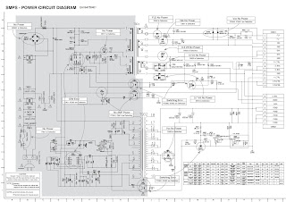
Power board (SMPS) circuit diagram
Click on the pictures to zoom in
Working Principle of the Unit
1. ATV PAL signal flow
Receive RF PAL analog signal and sent it to XC5200C (D/A silicon Tuner controlled by main chip MSD309PX through I2C bus) to be demodulated, then differential IF signal is send out to main chip MSD309PX analog demodulation to be demodulated to get analog CVBS video signal and SIF sound signal.
CVBS video signal is processed by back-end video decoder, anti-interlacing part, video processor and zoom controller, then a pair of LVDS signals are outputted to chip MST6M30 to be processed by modules of 120HZ, MEMC and 3D effect, then two pairs of LVDS signals are outputted to drive display panel.
SIF sound signal is processed by back-end demodulator to get analog sound signal, then processed by pre-amplifier, acoustic effect processor and volume controller to get two parts of signals: the analog part of signal is sent to earphone amplifier MAX9820 to be amplified and then outputted to earphone jack;
the digital part of signal I2S is sent to digital audio power amplifier TAS5711 to be processed by D/A converter and power amplifier, then outputted to drive speakers.
2. DVB-T signal flow 
Receive RF DVB-T digital signal and sent it to XC5200C (D/A silicon Tuner controlled by main chip MSD309PX through I2C bus) to be processed by down-frequency-conversion, then differential IF signal is send out to main chip MSD309PX digital demodulation to be demodulated, then standard parallel transmission flow is outputted to back-end demultiplexer and decoder to be processed.
Video channel: demultiplexing digital video signal is processed by MSD309PX decoder and video processor, then a pair of LVDS signals are outputted to chip MST6M30 to be processed by modules of 120HZ, MEMC and 3D effect, then two pairs of LVDS signals are outputted to drive display panel.
Audio channel: demultiplexing digital audio signal is processed by MSD309PX decoder and audio processor, then double-sound-track analog audio signal (stereo) is outputted to MSD309PX to be processed by preamplifier, acoustic effect processor and volume controller to get two parts of signals: the analog part of signal is sent to earphone amplifier MAX9820 to be amplified and then outputted to earphone jack; the digital part of signal I2S is sent to digital audio power amplifier TAS5711 to be processed by D/A converter and power amplifier, then outputted to drive speakers.
3. AV input signal flow
AV video signal is inputted to main chip MSD309PX to be processed by video decoder, anti-interlacing part, video processor and zoom controller, then a pair of LVDS signals are outputted to chip MST6M30 to be processed by modules of 120HZ, MEMC and 3D effect, then two pairs of LVDS signals are outputted to drive display panel.
AV audio signal is processed by voltage divider, resistance matcher and AC coupler, then sent to main chip MSD309PX to be processed by acoustic effect processor and volume controller to get two parts of signals: the analog part of signal is sent to earphone power amplifier MAX9820 to be amplified and then outputted to earphone jack; the digital part of signal I2S is sent to digital audio power amplifier TAS5711 to be processed by D/A converter and power amplifier, then outputted to drive speakers.


Sony TA DX8 – Integrated Stereo Amplifier Schematic – Exploded view - Australian model

$
0
0
DIN power output -75 + 75Watts (6 oHms)
Continuous power output - 100 + 100 Watts (6 oHms)
Used ICs: STK402-1005, M5218AP, BU4052BC
Power and Panel board: Schematic and PWB
Main board: Schematic and PWB
Exploded view
Click on the pictures to magnify

Sony RDR HXD790 DVD Recorder – How to enter service mode, adjustments, How to take the disc out at emergency, faults diagnosing, SMPS schematic

$
0
0
Sony RDR-HXD790/HXD795, RDR-HXD890/HXD895, RDR-HXD990/HXD995/HXD1090, HXD1095
Remote control: RMT- D251O, D251P
Australian Model
RDR-HXD890, HXD990
DISK REMOVAL PROCEDURE IF THE TRAY CANNOT BE EJECTED (FORCED EJECTION)
1. Remove the upper case.
2. Insert the stiff wire in the hole and eject the tray.
NOTES DURING THE FORCED EJECTION
1. If the forced ejection is executed while a blank disc media (DVD±RW, ±R) exists on the tray
* Insert a DVD-ROM (DVD test disc, DVD software available on the market, or the like) in the tray and then close the tray.
Note1: If you close the tray while it is empty, ejection of the tray becomes impossible.
Note2: If you close the tray with a CD disc inserted in it, the CD can be ejected. However, if you close the tray while it is empty, there can be a case that ejection of the tray becomes impossible.
Note3: Even if you replace the DVD drive unit while the tray remains under the state as described above, the situation cannot be improved.
2. If the tray cannot be ejected while the disc is not inserted
* Execute the forced ejection.
* Insert a DVD-ROM (DVD test disc, DVD software available on the market, or the like) on the tray and try to close the tray. (There are cases that it recovers the trouble.)
3. Contents of forcefully ejected blank disc media (DVD±RW, ±R) can be damaged. (There can be a case that initialization is also impossible.)
MODEL NAME SETTING METHOD WHEN ENGINE IS REPLACED
Required equipment:
* Remote controller (RMT-D251O/D251P)
* Service remote controller (Part code: J-6090-203-A)
* Monitor.
Model name delete method
1. Turn the main POWER ON.
2. Press the following buttons on the service remote controller in this order.: “ESC” > “CHAP” > “1”
* Confirm that the above operation is performed in the state that the screen has exited all settings such as “Home Menu” or “Simple Setting”.
3. Turn the main POWER OFF.
4. Turn the main POWER ON.
5. Find out the tentative model name from the Correspondence Table  for the client machine. Then, enter the 4-digit “Input No.” on the screen using the service remote controller.
6. The model name setting method is complete. (Screen disappears.)
* Upon completion of the model name setting, be sure to press both “ENTER” and “3” simultaneously on the service remote controller without fail. It sets the remote control code “3”.
Symptom: If the following operation is performed, set won’t be able to be restored.
Remedy: Must not be performed the following operation using service remote.  If it is performed, set won’t be able to be restored.
And if set is broken by the operation, we can’t guarantee the set when pressing in order of the following button.
* [ESC] > [STEREO]
([ESC] > [Any button which is not described in SM])
HOW TO DIAGNOSE HDD FAILURE
Defective HDD
There are four symptoms of defects in the HDD.
1. “E01” is displayed on the FLD. (The HDD is unauthorized.)
2. “E02” is displayed on the FLD.
3. When playing a video, MP3, or JPG, contents freeze.
4. Irregular noises from the HDD
HDD Recognition status
How to enter Recognition status and sub screen mode.
• While the GUI screen is not displayed, use the service remote controller and press “ESC” key followed by “DISP” key.
• While the first screen is displayed, press “DIG/ANA” key repeatedly until the desired sub screen is displayed.  
The sub screens change.
Factory Check
1. Pull out and then reconnect the AC cable.
2. Press “ESC” key followed by “P.RUN” key to start Formatting.
3. When “B COMPLETE” appears, the Factory Check is complete.
4. Press “Power” button. The unit starts normally.
When “Factory Check” has finished completely without error , reset “Recording Error History” and “A TA/ATAPI History Error” with the Clear key
Note: Write down the HDD information on the HDD return sheet before replacing the HDD.
SERVICE MODE
When performing “Factory Check”, the data saved to the HDD by the customer is erased.
Obtain customer consent before performing “Factory Check”.
“Recording Error History” and “ATA/ATAPI History Error”, 
Final Check
SELF TEST (SMART TEST)
This is a simplified diagnosis for the HDD.
A serious failure in the HDD can be detected with this test.
Time required for testing: Approx. 60 sec.
How to start/terminate the diagnostic program
Use the remote control unit for servicing.
• How to start: Press the following keys in this order; “ESC”, “CX”, “0”, and “1” keys. 
• How to terminate: Press “ESC” key.
Execute Self-Test.
• Press “3” key on the remote control unit for servicing while the menu screen is displayed.
• When the following screen is displayed, press “1” key to start the Self-Test.
Diagnosis results
* Without an error: “. . . Completed” is displayed.  Then, proceed to the Extended Self-Test.
* With an error: “. . . Error” is displayed. Look at the number in Test Result.
If the place value for tens is 1 or 2, execute the Self-Test again.
If it is from 3 to 7, the HDD must be replaced.
Note: If the result of the second test is the same, replacement of the HDD is required.
Performance Check
Press “ESC” key, then “A.MON” key.
This is a reading test across all sectors of the HDD.
Data recorded on the HDD will not be erased, because no writing operation is performed.
Time required for testing: Approx. 45 min/160 G 75 min/250 G 130 to 150 min/500 G
When “Performance Check” finishes completely without error, reset “ATA/ATAPI History Error” with the Clear key.
FL Display Flow
* The logo for “Factory Check” and “Performance Check” is recorded in “ATA/ATAPI History Error”
Notice of traverse mecha (TM) exchange.
For TM exchange, refer to SM below.
Service manual:RW6G/
G TRAVERSE MECHANISM REPAIR MANUAL(9-885-951-1*)
How to get it: 1.Open Service manual home page of ESI.
2.Input RW6G into ”Model Name”.
3.Click “Search” button.
SMPS schematic
Click on the pictures to zoom in

Samsung Galaxy Note-5 Smartphone – how to replace the rear camera, front camera and earpiece

$
0
0
Samsung Galaxy Note 5 rear camera replacement, front camera replacement and earpiece replacement share most the same steps, so show them together.
Rear camera, front camera and earpiece
Remove the Sim card tray.
Remove the S Pen.
Remove the back cover.
Remove the screws.
Remove the middle housing.
Remove the battery. But it's not necessary. You also can just release battery connector from motherboard.
Release the connector on the board.
Release the USB board connector on the back and remove the motherboard from front assembly
Remove the rear camera
Remove the front camera and noise-canceling mic
Remove the earpiece assembly.
To reassemble your device, follow these instructions in reverse order.
TOOLS: needed
Heat Gun (1)
iFixit Guitar Picks set of 6 (1)
Small Suction Cup (1)
Phillips #000 Screwdriver (1)
Spudger (1)
PARTS: needed
Samsung Galaxy Note 5 rear camera (1)
Samsung Galaxy Note 5 front camera (1)

How to replace the broken screen – NX008HD8G Nextbook

$
0
0
Nextbook NX008HD8G Screen Replacement
Use this guide to replace a broken screen. Sliding the plastic opening tool between the back panel and the front glass can be difficult. This guide is relatively simple, mainly unscrewing
and disconnecting a ribbon connector.
Using your finger, open the plastic tab to the right of the rear-facing camera.
Wedge your fingernail in between the back panel and the plastic tab and pull the plastic tab towards your body.
Using your finger, remove the SD card by pressing down on top of it (toward the bottom of the device) until you hear a clicking sound.
Once the card pops out, use your finger to pull the card completely out of the SD card slot.
Remove the 5 mm screw using the Phillips PH00 bit metal Screwdriver.
Use the plastic opening tool to separate the back panel by carefully sliding the narrow end of the tool between the front glass and back panel.
Use a second plastic opening tool to help pry the front glass from the back panel.
You will hear some cracking sounds when separating the front glass from the back panel.
That is okay! That is the back panel latches releasing the front glass.
Use your hands to completely separate the rest of the front glass from the back panel.
Do not to pull the device apart with too much force. If you do, you may break or bend the back panel.
Using the Phillips #0 bit with the iFixit screwdriver, remove the four 5 mm screws with the washers around them connecting the digitizer to the screen.
Using the Phillips #0 bit screwdriver, remove the two 5 mm screws connecting the motherboard to the back of the digitizer.
Using the flat end of the plastic spudger, open the black ribbon connector door on the right side of the motherboard.
Pull the ribbon out of the ribbon connector using your finger.
To separate the digitizer from the screen, tilt the device on its right side and use your other
hand to pull the battery to the right.
If you tilt the device too far the digitizer may fall out.
The upper left corner of the motherboard may be harder to disconnect from the screen.
To reassemble your device, follow these instructions in reverse order.

LG42LE5500 - LED Backlights 1080PDirect View LCDTV – SMPS (Power supply) board [EAY60803101] troubleshooting-repair

$
0
0
How to troubleshoot and repair Power board  of  LG42LE5500 LED TV
Part number: EAY60803101
POWER SUPPLY SECTION
This switch mode power supply develops Stand By 3.5V at all times when AC is applied.
At power on, it develops 12V and 20V for the Main board.
It develops 120V for the LED Backlights
This power supply draws less than 1 watt during stand by mode. The fuse F101 and F103 reads 7.6V (from hot ground) during this time.
When the controller chip receives the PWR-ON command 3.36V via P201 Pin 1, the primary section increases its current supplying ability. Both Primary fuses F101 and F103 now read a little more than 395V.
T102 delivers AC to D206 which develops the 120V for the LED backlights.
P201 Connector: (To Main Board)
12V (11.43V) is routed out P201 pins 17, 19 and 21 and 20V (21.27V) is routed out P201 pins 2, 3 and 4.
P204 Connector: (To Panel LEDs)
120V is routed out P204 pins 1 and 12.
P205 Connector: (To Panel LEDs)
120V is routed out P205 pins 1 and 12
Power Supply Start Up SequenceClick on the pictures to magnify
42LE5500 Television Turn On Commands Circuit Drawing.
Power Supply Board Low Voltage Test
AC Should not be applied at any time while adding jumpers or While unplugging connectors as damage to the circuit Board may occur.
a) When AC is applied, the SMPS “MUST” be producing STBY 3.5V on pins 9, 10, 11 or 12 of P201.
If 3.5V Standby is not being generated, the SMPS is defective and must be replaced. There is no need to continue with the next test.  But, make sure AC is arriving at the connector SK101.
(b) Unplug P8000 on the Main Board to make insertion of the Jumpers easier. Use P700 Side to insert resistors.
No Back-light during this test
Add a jumper between (3.5V STBY) pin 7, 8, 9 or 10 and Pin 1 (PWR_ON). Apply AC.
This will turn on the power supply, relays will click.
a) Check that the 24V and 12V power supplies are turned on,
* P201 (12V pins 17, 19 and 21)
* P201 (24V pins 2, 3 and 4)
* P204 and P205 (120V pins 1 and 12) to the Panel. (Or check D206 + lead)
(2) Remove the AC power.
Power Supply Board Back-light Test
Continue if the 1st test was OK.
Leave original jumper in place.
(3) Add another jumper between (STBY_3.5V)
pin 9, 10, 11 or 12 and Pin 18 (INV_On).
(4) Apply AC Power. (Simulating a Power and Back-light On command.)
Back-lights Normal
a) If normal, the backlights should turn on.
SMPS OK, Inverter OK.
Backlights Abnormal:
a) Recheck all connections.
b) Confirm the INV On/Off line pulling up to at least 3V.
c) Check the connections to the Panel.
If the Inverter On command is pulling up to 3V and the 120V is being generated from D206 + lead, See the Inverter Section of the Power Supply for additional checks.
Note: If either P204 or P205 is disconnected, the backlights will come on, but shut off in 4 seconds.
REMOVE AC POWER
42LE5500 Inverter Part of the SMPS
Power Supply Connector P201 Voltages
Power Supply Connector P204 / P205 Voltages

LEDPlus LG 42LE5500 – How to enter the service mode, how to update the software

$
0
0
Firmware update, EDID download procedure: LG42LE5500 LEDPlus TV
Remote Control - AKB72914003
Power board: EAY60803101
Main board: EBU60904603
Basic Troubleshooting Steps
Define Look at the symptom carefully and determine what circuits could be causing the failure. Use your senses Sight, Smell, Touch and Hearing. Look for burned parts and check for possible overheated components. Capacitors will sometimes leak dielectric material
and give off a distinct odor. Frequency of power supplies will change with the load, or listen for relay closing etc. Observation of the front Power LED may give some clues.
Localize After carefully checking the symptom and determining the circuits to be checked and after giving a thorough examination using your senses the first check should always be the DC Supply Voltages to those circuits under test. Always confirm the supplies
are not only the proper level but be sure they are noise free. If the supplies are missing check the resistance for possible short circuits.
Isolate To further isolate the failure, check for the proper waveforms with the Oscilloscope to make a final determination of the failure. Look for correct Amplitude Phasing and Timing of the signals also check for the proper Duty Cycle of the signals. Sometimes
“glitches” or “road bumps” will be an indication of an imminent failure.
Correct The final step is to correct the problem. Be careful of ESD and make sure to check the DC Supplies for proper levels. 
To access the Service Menu.
1) You must have either Service Remote. (PART NUMBER: 105-201M or  MKJ39170828)
2) Press “In-Start”
3) A Password screen appears.
4) Enter the Password.
Note:A Password is required to enter the Service Menu. Enter; 0000
Note: If 0000 does not work use 0413.
Software Updates (New and Changed Functions)
A wireless Internet Connection will work for Automatic Software Downloads., however if there are problems completing download, a Wired Internet Connection is preferred
For network setup assistance, press the green button for the Simple Manual With Software Update Highlighted, Press Select on Remote
Continue on next page
Bring up the Customer’s Menu then Press the Red button on Remote Scroll down to item 9 Network Connections.
Automatic Internet Software Update
*Off : Automatic Software update does not work
*On : if new Software released, Software download notice appears at turn on with two choices, Yes and Remind Me Later.
Check Update version
* comparison current software version and Released software version.
Additional TV Checks can be made by Scrolling down.
Picture, Sound and Network Test.
After completion of the test, a Pop up menu is displayed with pre-loaded back ground picture.
Select NO if everything is OK.
If you select Yes; Service call number, Model name, SW version and serial No. is displayed.
Note: Confirm the “Suffix” of the model number.
If the Main board is replaced, the Model and Serial number must be reinserted into memory. See Model Number D/L.
USB Automatic Software Download
Create an LG_DTV folder on the USB Flash Drive.
2) Copy new software (xxx.epk) to "LG_DTV" folder. Make sure to have correct software file.
3) With TV turned on, insert USB flash drive.
4) You can see the message “TV Software Upgrade”
5) Cursor left and highlight "START" Button and push “Enter” button using the remote control.
6) You can see the download progress Bar.
7) Do not unplug until unit has automatically restarted.
8) When download is completed, you will see “COMPLETE”.
9) The TV will be restarted automatically.
CAUTION:
Do not remove AC power or the USB Flash Drive.
Do not turn off Power, during the upgrade process.
Software Files are now available from LGTechassist.com
Manual Software Download
Prepare the Jump Drive as described in the “USB Automatic Download” section and insert it into either of the USB ports.
Bring up the Customer’s Menu and scroll to “OPTIONS”.
Press the “FAV” key 7 times to bring up the Manual Download Screen.
Highlight the Software update file and press “SELECT” to begin the download process.
Example of files found On the Jump Drive.
Downloading EDID Data Pg 1 of 2
1) Press “ADJ” key.
2) Select menu,
Either “PCM EDID D/L” or AC3 EDID D/L
3) Highlight “Start” then Press “Select” key.
4) When Writing appears
Downloading in progress.
5) Downloading Complete.
Click on the pictures to zoom in

Samsung HTC330 - How to change the region code, How to initialize, Protection circuit operations and more

$
0
0
Samsung Digital Home Cinema System HT-C330 - Model Code : HT-C330-XSS
Buyer-Region Code Setting Method
The inserting method of Region Code after replacing the Main PBA
When replacing the Main PBA and System Micom should be inserted the region code.
* The set is not working properly if you don't insert the region code.
* The region code is inserted by the remote control.
Procedure
1. Press the “AUX” button on the remote control.
2. Press the "TUNER MEMORY" button on the remote control during 4~5 seconds.
3. After step (2), you can see “TEST” on the VFD.
4. When you see “TEST” on VFD, Insert number “4”, “6” to start Region Code setting mode.
5. After step (4), you can see “- -” on the VFD.
Insert the Region Code (Below table) corresponding model with “0 ~ 9” buttons on the remote control.
6. After step (5), you can see “15 USA” on the VFD.
It means that currently System Micom program is installed by USA specification.
In case of System Micom and EEPROM problem, you can apply to this.
For example, during Updating program of System Micom, if Updating fail is happened, it is impossible to turn on the system from stand-by status.
The system will keep the stand-by status continuously, and the touch-key function will never work.
In this case, you have to change System Micom, and set up the Buyer Region code again.
In case of EEPROM, you don't need to care about it.
After set-up the Region code, System Micom will store the information of the region code to EEPROM automatically.
Initialization and Upgrade
DVD flash Initialization and Update -  Checking out MICOM & MPEG flash Version
1. Select the Setup-Support-Product information to check the Program version on the screen and front VFD display
DVD flash Initialization & Update (firmware)
1. Prepare USB that contains SSP file(Micom) and ROM file(MPEG) for Update.
2. Select the folder which has update file, then “Updating” will appear on the screen.
After completing the update, the power will go out and on, then tray will open automatically.
3. Make the unit “NO DISC” state if there is a disc and then close the tray.
4. Press “STOP” button of Main Unit 5 seconds more, display indicator shows “INITIALIZE” then power go out.
5. Initialization complete.
SMPS and amplifier schematics
Measures to be taken when the Protection Circuit operates
Operation of Power Block Protection Circuit
The Condition of Power Protection Active.
1. Voltage of SMPS’s PVDD (+22.5V, CON2) is higher or lower than Standards.
Normal Condition Voltage Range: PVDD (+22.5V, CON2): about 22.5V
2. Over-current occurs to AMP IC. (Over-output or Output short)
3. AMP IC’s temperature exceed 150°C
4. No supply voltage on GATE DRIVER
AMP Power Stage TAS5342

1. OTW: Active, IC’s inner temperature exceeds over 150°C.
(Under 2.7V, Protection Circuit wills Active)
2. SD: Shout down.
(Under 2.7V, Protection Circuit wills Active)


AWA MSDV 2413 LCD TV - How to unlock, how to update the firmware, How to enter the service mode, Universal remote control set-up codes

$
0
0
How to enter into the factory mode. [Service Mode]
1.You can press "source-2-5-8-0" to go into factory setting.
Press the key "exit" to shut the factory setting.
content:
1: ADC setup: set ADC value of YUV,VGA. It can also be auto-set. Adopt 100% color bar to yuv and Checkerboard signal to VGA.
2: Adjust the brightness and contrast ratio of each signal, which do not affect the value of user's menu.
3: adjust the color temperature and white balance of each signal source.
4: SSC to adjust the spectrum for passing the EMC test.
5: special set
1) 2hour off-- for Aging test
2) WDT --watch dog
3) white pattern --set pure color output for the panel, used at the checking and aging test for panel.
4) reset
5) set the recorder
6) set power-on screen display.
6: QMAP adjust :adjust color quality.
7: PEQ set sound EQ
8: SW information: to check the sofeware information
9: UART DEBUG : Access to serial port and connect a computer if set to HK.
10: BMTEST :cpu check the CPU
The last line is SW Ver.No
LOCK MENU
You can lock system, set password, block program and set parental guidance Once you set the lock system to on, you cannot search the channels or change any programs.  The default pass word is 6666.
Block program: Press Up/Dn to choose the program ,press teletext green button to block the program. If you want unblock the program,  enter the main menu , input the password, then press green button again.
Parental guidance: Press Left/Right to choose rating.]
NOTE
Restore factory default will clear all the programs and password.
How to update software
Haier MSD306 F/W upgrade with USB SOP
Ready for F/W Upgrade
1 Prepare a USB memory .
2 Copy the software fle (merg.bin) from your computer to the USB memory, and remove it from computer’s USB port.
1.F/W Upgrade.
2, then input USB , press "MENU" and choose "update software", and then press "OK".
3, Now you should choose "Yes", TV begin to update. You should reset TV after update.
Note:When Upgrade on the process, please don’t Power-Off.
HDMI Connections
When the source device(DVD player or Set Top Box) supports HDM
How To Connect
1. Connect the source device to HDMI port of this TV with an HDMI cable (not supplied with this product).
2. No separated audio connection is necessary.
How To Use
If the source device supports Auto HDMI function, the output resolution of the source device will be automatically set to 1280x720p.  If the source device does not support Auto HDMI, you need to set the output resolution appropriately.
To get the best picture quality, adjust the output resolution of the source device to 1280x720p.
Select HDMI input source in input source option of Select Main source menu.
When the source device(DVD player or Set Top Box) supports DVI
How To Connect
1.Connect the source device to HDMI port of this TV with a HDMI-to-DVI cable(not supplied with this product).
2. A separate audio connection is necessary.
3. If the source device has an analog audio output connector, connect the source device audio output to DVI Audio In port located on the PC port.
How To Use
If the source device supports Auto DVI function, the output resolution of the source device will be automatically set to 1280x720p.
If the source device does not support Auto DVI, you need to set the output resolution appropriately.
To get the best picture quality, adjust the output resolution of the source device to 1280x720p.
Press the INPUT button to select HDMI input source in input source option of Select Main source menu.
Universal remote control set-u codes for AWA TVs
0018 0049 0101 0131 0152 0161 0181 0193 0194 0195 0226 0320 0379 0426 0433 0465 0601 0616

Philips FWM539 Mini Hi-Fi system – power amp, CD board and MCU board schematic

$
0
0
Used ICs: HEF4013, 74CT04, NJ4556AM,LM324, TDA8920TH x 3, ML C8800, HT1381, WM8781, 74HC157A, BU9543, TDA7073A
RMS output power
1KHz (Low channel-both channels driven) ................... 100 W per channel
10KHz (High channel-both channels driven).................. 100 W per channel
Total output power ..........................................................580 W
SPEAKERS
System 2-way; double port bass reflex
Impedance .............3 Ω
Woofer ..................2 x 5.25”
Tweeter .................2 x 1.75”
SUBWOOFER
Impedance ........................6 Ω
Subwoofer driver .............. 8”
Sub-woofer output power ..180 W
Power amplifier circuit diagram [Click on the pictures to zoom in]
MCU board schematic
CD board schematic
Exploded view
LIQUID LENS CLEANING
Because the material of the lens is synthetic and coated with a special anti-reflective layer, cleaning must be done with a non-aggressive cleaning fluid. It is advised to use “Cleaning Solvent
Before touching the lens it is advised to clean the surface of the lens by blowing clean air over it. This to avoid that little particles make scratches on the lens.
The actuator is a very precise mechanical component and may not be damaged in order to guarantee its full function.  Clean the lens gently (don’t press too hard) with a soft and clean cotton bud moistened with the special lens cleaner.  The direction of cleaning must be in the way as indicated in the picture above.

How to replace HTC Desire 510 Front and Main Cameras.

$
0
0
HTC Desire 510 / RIO - How to disassemble the device and replace the main or front camera
BATTERY REMOVAL
Switch off the phone, remove the battery and any installed SIM and memory cards
Remove 7x Torx T5 screws.
Use a plastic tool to remove the rear bezel
The loudspeaker is on the inner side of the rear bezel.
FLEX CABLES DISCONNECTING
Disconnect the touch screen flex cable.
Disconnect the light sensor flex cable.
Unstuck the vibra-motor from the middle frame.
Remove the coaxial antenna cable from the middle frame.
The LCD display flex cable is connected to the bottom side of the board.
LOGIC BOARD REMOVAL

At the upper left side, the board is held by a plastic locking clip. Use a plastic tool and start the separating from here.
Gently disconnect the LCD display flex cable.
Now remove the logic board.
Front and Main Cameras
To reassemble your device, follow these instructions in reverse order.

Hitachi C21 F800 – PAL-SECAM-NTSC – How to enter service mode, adjustments, SMPS and full schematic - Universal remote control code list for Hitachi TVs

$
0
0
Remote control handset - CLE-937
Used ICs: KA0765(SMPS control), 24C16(Memory), TDA9367(Syscon-Chroma Jungle), TDA9874, TDA8944j(Audio output amplifier), TDA9859(Input Selector), LA78040(Vertical Scan output), BS2901(Line Output Transformer / LOT / FBT), 2SD1651C(Horizontal scan output transistor)
If CHILD LOCK is set to ON, you can access the TV by remote control unit only.
You may keep the remote control unit out of reach to prevent children from any unauthorized access to the TV.
In AV mode, only COLOUR SYS will be displayed in [TUNE] menu.
If COLOUR SYS is set to AUTO, the color system will be detected and selected automatically.
If the signal reception is poor, an incorrect color system may be detected and selected. You can rectify this problem by setting the color system (PAL, NTSC, NTSC4.43 or SECAM) manually.
When SKIP is set to ON, the channel number will be changed from green to grey.
When using FINE TUNE to adjust the signal reception, the channel number will be changed from green to yellow; if SKIP is set to ON at the same time, the channel number will be
changed from yellow to white.
TO RELEASE THE CHILD LOCK, IF THE SET IS LOCKED
1.  Press the  Menu button (4) times, or press the Setup button on the remote control. 
2. Select the desired item using the P+/P- buttons. 
3. Use the Vol+/Vol- button to adjust the child lock setting. Normal setting is OFF
4. press the Menu button (3) times, or press the Setup button to exit to TV mode. 
ALIGNMENT INSTRUCTION (3P31Chassis – C21F800)
The main power is 100~240V 50/60HZ . Please be careful when you are servicing.
Don t short any two soldering points, which should not be shorted and don t touch any components, which should not be touched.
Disconnect the power plug form the wall outlet before servicing.
For safety reasons, all components replaced should be identical with BOM.
Before alignment, ensure the TV set has heat run for at least 30 minutes and degauss the CRT thoroughly with demagnetizer.
The data of EEPROM must be stored before the adjustment for main chassis.
Power Adjustment
Connect a 100W bulb across C616 and AC 200V power to CN601. If the bulb lights up, the voltage is normal and power is ok, else please proceed servicing.
SMPS part schematic
Full schematic
Enter factory mode
Press the [sound mode], [recall], [CH I / II] keys on remote control unit to enter factory mode.
Press 0-9 numeric keys to enter factory menu.
Select the item using the [P+] and [P-] keys and adjust using the [V+] / [V-] keys.
Press [Recall] key to exit factory mode.
Screen Voltage Adjustment(Key 9)
Press PIC. MODE key to set picture in STANDARD mode at no signal input
Press key [sound mode], [recall], CH I / II] in turn to enter factory mode.
Press 0 key and a horizontal line will display on the screen.
Adjust the screen knob of FBT so that the horizontal line is just visible.
Press other keys to go to the normal work status.
Vertical Size And Pin Cushion Adjustment (Key 8)
Receive 50HZ cross hatch pattern.
Press PIC. MODE key to set picture in STANDARD mode.
Adjust VSLOPE to obtain half of the crosshatch.
Adjust VSCOR to obtain picture s best vertical pin cushion.
Adjust VSHIFT to obtain picture s vertical center at the center of CRT screen in factory mode
Adjust HSHIFT to obtain picture s Horizontal center at the center of CRT screen in factory mode.
Receive 50HZ monoscope pattern.
Press PIC. MODE key to set picture in STANDARD mode.
Adjust VAMP to obtain picture s vertical overscan more than 90% in factory mode.
Receive 60HZ cross hatch pattern. Press PIC. MODE key to set picture in STANDARD mode.
Adjust VSLOPE to obtain half of the crosshatch.
Adjust VSCOR to obtain picture s best vertical pin cushion.
Adjust VSHIFT to obtain picture s vertical center at the center of CRT screen in factory mode.
Adjust HSHIFT to obtain picture s horizontal center at the center of CRT screen in factory mode.
Receive 60HZ monoscope pattern.Press PIC. MODE key to set picture in STANDARD mode.
Adjust VAMP to obtain picture s vertical redisplay ratio more than 90% in factory mode.
OSD Position Adjustment
Menu OSD position adjustment: Receive 50/60HZ cross hatch pattern.
Press PIC.MODE key to set picture in STANDARD mode .
Press KEY 5 in factory mode, adjust OSD VPOS
And OSD HPOS item to obtain menu OSD at the center of CRT screen.
White Balance Adjustment (Applied in factory)(KEY 9 )
Normally, this TV can auto adjust white balance, but for some CRT maybe need to adjust white balance manually.
Set BRIGHTNESS and CONTRAST at normal status, receive GREY SCALE enter factory mode.
Press and set BD at 31.Adjust RD and GD to obtain white balance.
RF.AGC Adjustment(KEY 7 )
Receive 60dB RF signal. Connect Digital voltmeter positive terminal to tuner AGC terminal and negative terminal to GND.
Enter the AGC item in factory mode by the REMOTE CONTROL.
Method: Press key [sound mode], [recall], CH I / II] to enter factory mode, then press Key-7 and select AGC item by [P+] and [P-]
Adjust keys [Vol+ / Vol-] to obtain 2.8V digital voltage meter reading or till no NOISE on screen.
Press RECALL key to exit factory mode.
Universal remote control set-up codes to check with Hitachi TVs [both CRT and LCD types]
HITACHI: 0014 0018 0020 0022 0033 0044 0049 0050 0074 0086 0099
0101 0102 0104 0107 0110 0119 0126 0127 0150 0152 0161
0162 0165 0166 0168 0171 0178 0182 0186 0203 0213 0218
0219 0231 0233 0238 0309 0379 0456 0475 0611 0613 0622
0631 0633 0636 0671 0795

HITACHI FUJIAN: 0013 0123 0161 0195 0238 0380

HITACHI C21-FL21F CRT TV – LED blinking codes, Service mode, Initialization, IIC adjustments and more…

$
0
0
Used ICs: STR F6454R(SMPS control), MSP34J7G(NICAM processor), TDA9365 / TDA9384 / TDA9386(MICOM Chroma Jungle), TDA9859(Ausio output IC), ba7604N, TDA8356(Vertical Scan output IC)
In V3AR ,failure of Main devices can detect by the blinking indication of LED at front panel.
( Example : LED blinking time is 2 in cycle I002 is out of order. )
If an IIC error occurred, the LED, D001 blinks at 1Hz, 50% duty cycle.
The blinking times are as below
Click on the pictures to magnify
Selection and CPU circuitry
IC type, TDA9381/86/65 performs functions like IIC controls, channel selection, on-screen display, search tuning, systems selection amongst others. The pin's functions of TDA9381/86/65 are presented in the table shown below.
The Tuner (U001)used on V3AR chassis is powered up by the 5V supply. It is IIC bus controlled and covers VHF, UHF, CATV Band (Mid, super, and hyper).
The IF output from Tuner ( pin 11 of U001) is applied to the amplifier Q201.
For multi-system model with M-NTSC, switchable saw filter is used. Q001 at pin 2 of X003 servers to select the IF signal between M/N mode to other modes ( e.g. B/G, D/K ) before demodulation is carried out at I001.
i.e. at M mode: Base of Q001 High
I001 (TDA9381/9386/9365) besides begin the microcontroller, incorporates video / chroma / deflections / teletext features and video/audio switching. It performs auto color identification of  PAL/SECAM/NTSC, sync separation , AFC, HV oscillator and output RGB signals.
IF signal is sent to I001 pin 23 and 24 for demodulation. For MONAURAL and AV STEREO mode, the demodulated signals are sent for video and audio selection. For NICAM/A2 mode, the demodulated signals are sent for video processing only.
The composite video signals after demodulation are sent to a series of band pass filters (X004 - X006) through pin 38 of I001.
The selected RF video signal is sent to pin 40 of I001 and output AV terminal. The external video signal from input AV 1 and 2 terminal also goes through pin 38 to output AV terminal. This is done by use of internal switch control.
Audio mode switching
For MONAURAL (without NICAM/A2) sound models, two audio switching is carried out. The RF audio signal after demodulation in I001 is output at pin 28 of I001 to pin 10 of I401. I401 perform audio selection using control signal between the RF audio signal and external audio signal input (pin 8) of I401. The audio output at pin 6 of I401 is sen
to output AV terminal.
The external audio input is also sent to pin 35 of I001 to perform the second audio switching with the RF audio signal in I001. The selected audio signal goes through volume control before output at pin 44 of I001 to L(pin2) and R(pin 5) of I402. Amplification took place and output at L (pin12) and R (pin7) of I402 to the speakers
For NICAM/A2 sound models, the IF signal is input at pin 1 of X002 (saw filter) and output at pin 4 and 5 to pin 28 and pin 29 of I001. After demodulation, the audio signal output at pin 35 to NICAM PWB (pin 2 of EN01) for NICAM processing. The NICAM audio output at pin L (pin 10) and R (pin 11) of EN01 goes to SOUND PWB at pin 9 and 10 of EA01 For AV STEREO sound models, the audio signal is output at pin 44 of I001 and goes to SOUND PWB at pin 9 and 10 of EA01.
Audio input (L and R) from AV 1 And 2 terminal are input to pin 1 - 4 of EA01. Audio switching, volume control, treble and bass are processed at IA01 (TDA9856). The L (pin 7) and R (pin6) output at EA01 goes to output AV terminal The L (pin 12) and R (pin 11) at EA01 goes to I402 for amplification before sending to the speakers.
POWER SUPPLY CIRCUIT
Commutating voltage from AC output rectified by D901A and produces approximately 300V to pin 3 of I901.
Current flowing through R904, R917, causes I901 pin 4 to initially turn on.
Secondary voltage are then induced winding V1 - V2 in T901, I901 supply voltage is obtained via R906, D906, C909 and applied to pin 4 of I901, thereby maintaining I902 switching operation. Secondary voltage in S1, S3 winding is rectified by D951 to produce +B = 95V which is smoothed by C953. S2, S4 winding produces 16V from D952, and this is smoothed by C956.
Error amplifier Q951 is set to a pre-determined level by resistor network R952 - R956, and reference voltage D957 Should the +B voltage rise, base voltage of transistor Q951 will become more positive, and this difference is amplified by the error amplifier Q951. An output is applied to I901 feedback pin 1 through optocoupler (CTR) I902 and controls ON time of I901 internal circuit . In this way, +B voltage is regulated and maintained at a constant level.
D973 offers protection that it should the voltage level rise excessively
When the standby mode is selected, pin 1 of I001 will go " low " . As a result Q954 and Q955 are turned off, and the supply voltage for the horizontal start of pin 33 of I001 though R980/D980/R071 disappears. Therefore shutting down the deflection drive stages of I001, deflection output stage will then cease for as long as the standby condition exist.
Shipping Data of IIC Service Mode.  (apply only when the memory IC, I002, change.)
1. Select the adjustment item, 323(Initialization of memory IC, I002) by pressing the Up or Dn cursor button on Remote control handset.
2. Set data of adjustment item, 323 to "01" by pressing the Left or Right cursor button on Remote control handset.
3. Press the RECALL button on Remote control handset to memorize the data.
The data of adjustment item, 323 is changed to "00" after all memory IC's data are initialized.
4. Press AC power switch to turn off the TV set.
5. Press AC power switch to turn on the TV set.
Result : The memory IC, I002 is initialized.
6. After initialization, set the shipping data will be displayed.
7. Go to previous page and adjust the IIC data as in Table below.
IIC ADJUSTMENTS
Most of the adjustment items in the V3AR chassis are controlled by IIC. Adjustment items include video chroma IC (I001, UOC) control, sound multiplex ICs, horizontal & vertical deflection and others.
To start the IIC adjustment, first turn off AC power switch. Press and hold down the TV/Video local key and then press the power switch. Release both buttons after the Service Mode display appears on screen.
To select the adjustment items (e.g. RGB level, sub-brightness level etc…), press the Up or Dn cursor button on Remote control handset. To adjust the data of selected item, press Left or Right cursor button on Remote control handset .  After completing the adjustments, press the RECALL bottom on Remote control handset to memorize the data.
Press MENU button or turn off the TV set to end the IIC adjustment.
Schematic - Full

Viewing all 2033 articles
Browse latest View live


<script src="https://jsc.adskeeper.com/r/s/rssing.com.1596347.js" async> </script>