Quantcast
Channel: Electro help
Viewing all 2033 articles
Browse latest View live

HOW TO DISASSEMBLE - OLEVIA - LT-26HV - LCD TV - STAND - LCD MODULE - POWER MODULE - SYSTEM BAORD

$
0
0

DISASSEMBLE PROCEDURE
  • Loosen 4 screws as red circles.
  • Pull the Interface module to the right side and pull up as blue arrow.
  • Loosen 5 screws as red circles.
  • Loosen Tuner nut as blue circles.
  • Loosen 4 screws as red circles.
  • Take apart AV cover metal and Interface Board.
STAND MODULE
  • Loosen 7 screws as red circles.
  • Take apart the Stand Module.
  • Loosen 7 screws as red circles.
  • Take apart the Stand Cover and Stand Support Metal.
  • Loosen 4 screws as blue circles.
  • Take apart the Stand Bottom Metal and Stand Support Metal.
{CLICK ON PICTURES TO ZOOM IN}
BACK COVER
  • Loosen screws as red circles.
  • Take apart the Back Cover from TV.
SYSTEM BOARD
  • Loosen 8 screws as red circles ofFigure1, the screw locations are around the Shielding, every side has 2 screws.
  • Loosen 1 screw as blue circles.
  • Take apart the shielding.
  • Pull out of all wires.
  • Loosen 4 screws as red circles.
  • Take apart the System Board.
POWER MODULE
  • Pull out the power wires with Panel Inverter connector and System board connector as red arrows.
LCD PANEL
  • Loosen 10 screws marked in blue circles.
  • Loosen 4 screws as red circles.
  • Loosen 4 screws as blue arrows and blue circles.
  • If you take off the System Board and Power Supply before, you can direct take apart the Panel.
  • Be careful to take panel.
  • Loosen 10 screws marked in blue circles.
  • Loosen 4 screws marked in  red circles.
  • Loosen 4 screws as blue arrows and blue circles.
  • If you take off the System Board and Power Supply before, you can direct take apart the Panel side up as blue arrow.
  • Pull out the LVDS wire and Power wire.
  • Take apart the Panel Module.


OLEVIA - LT-27HV - LCD TV - HOW TO DISASSEMBLE - STAND REMOVAL - TUNER & INTERFACE

$
0
0


STAND MODULE
TUNER & INTERFACE MODULE

TELEFUNKEN - TKL3209S – LC32IE21 – LC32IE31 – BL3210S – LC37IL11 - HOW TO ENTER SERVICE MODE [Factory Mode] - MICOM RESET - Universal Remote Control Set-up Codes

$
0
0

REMOTE CONTROL BUTTONS & FUNCTIONS
SERVICE MODE
Power Off (Press "POWER" key).
  • Press "Menu" key
  • Press "Mute" key
  • Press "OK" key
  • Press "POWER" Key
  • Factory menu.
WHITE BALANCE
  1. Enter to Factory menu
  2. Press "OK" key or "VOL +" key.
  3. Auto-Cutoff: Adjusting Auto R, G, B Cutoff (Input Mode:PC-RGB,DVI,COMPONET)
  4. R-Cutoff, G-Cutoff, B-Cutoff: Adjusting Red, Green, Blue Gain (Input Mode: PC-RGB, DVI, COMPONET)
  5. Press "PR+" or "PR–" key: Select Sub Menu
  6. Press "VOL+" or "VOL-" : Adjusting Value
  7. Press "Menu" key: return Factory menu
  8. Press "Exit" key: exit
SOUND
  • Enter to Factory menu
  • Select menu
  • Press "OK" key or "VOL +" key
  • Press "PR+" or "PR–" key : Select Sub Menu
  • Press "VOL+" or "VOL-" : Adjusting Value
  • Press "Menu" key : return Factory menu
  • Press "Exit" key : exit
Adjusting Range
  • Dual ,A2 Stereo, Dolby, Woofer (0: Off / 1: On)
  • SC Prescale, FM Prescale, Nicam Presale : 0~255
OPTION-1
  • Enter to Factory menu
  • Select menu
  • Press "OK" key or "VOL +" key
  • Press "PR+" or "PR–" key : Select Sub Menu
  • Press "VOL+" or "VOL-" : Adjusting Value
  • Press "Menu" key : return Factory menu
  • Press "Exit" key : exit
 Adjusting Range
  • China Au, Text, TXT-List Mode, TXT-TOP, TXT-ACMS, DTV-Text, GAME (0: On / 1:Off)
  • TXT-Lang: 0~16 , Teletext Language.
OPTION-2
  • Enter to Factory menu
  • Select menu
  • Press "OK" key or "VOL +" key
  • Press "PR+" or "PR–" key : Select Sub Menu
  • Press "VOL+" or "VOL-" : Adjusting Value
  • Press "Menu" key : return Factory menu
  • Press "Exit" key : exit
Adjusting Range
200PR 0 : PR Number 0~99
1 : PR Number 0~199
SYSTEM 0 : Not Use
1 : BG/I/DK/L
2 : BG/I/DK/M
OPTION-3
  1. Enter to Factory menu
  2. Select menu
  3. Press "OK" key or "VOL +" key
  4. Press "PR+" or "PR–" key : Select Sub Menu
  5. Press "VOL+" or "VOL-" : Adjusting Value
  6. Press "Menu" key : return Factory menu
  7. Press "Exit" key : exit.
MICOM RESET
  • Press "PR+/-" key Select MICOM RESET
  • Press "OK" or "VOL +" key
  • Power off ,and Power on : Change System ID
  • All User Adjust value Reset
MEMORY CLOCK SET
  • Press "PR +/-" key Select MEMORY-CLOCK SET menu
  • Press "OK" or "VOL+" key enter to Sub menu
  • Default value
DQSPH0 2
DQSPH1 1
DQSPH2 2
DQSPH3 1
Recommend: Do Not Change.
Universal remote control set-up codes.
1180 1200 1215 1197 1165 1258 1239 1198 1036 1194 1289 1331 1052 1217 1202 1158 1039 1160
1214 1285 1269 1301 1376 1157 1123 1232 1051

LG RP21FD10 - SCHEMATIC DIAGRAM - Used ICs - TDA2006 – TDA7297/7296 – TDA7442 – LA7222 – AT24C04 – TMPA8801CSN – LA78040 – STR F6654 Power Switching

$
0
0


SCHEMATIC [FULL]

POWER SUPPLY SECTION ONLY
{CLICK ON SCHEMATICS TO ZOOM IN}

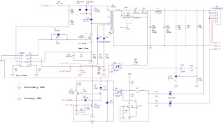
TV POWER SMPS - SCHEMATIC - USING QXXAVB325 [STR-6654] AS POWER SWITCHING - SE-130NH [VOLTAGE SWITCHING] & PC123F2/PC817 C or D Opto Coupler

$
0
0

POWER SUPPLY SCHEMATIC
CLICK ON SCHEMATIC TO ZOOM IN

HOW TO ENTER SERVICE MODE - NOBLEX 29TC 665 [Argentina] - Memory IC Replacement - Universal Remote Control Set-up Codes

$
0
0


MEMORY IC REPLACEMENT
   This set has an On-screen Service Menu system included in the CPU that allows remote operation for most of the service adjustments.
IC802 [EEPROM] REPLACEMENT
   When IC802 (EEPROM) is replaced, IC801 (CPU) will automatically write the initial reference data into IC802 for basic TV operation.  However, the bus data should be checked and some bus data should be set up before attempting the service adjustments.
Initial Bus Data Setup
Note: When IC802 (EEPROM) is replaced, following Service Menu should be set up for proper TV operation before attempting the service adjustments.
{CLICK ON PICTURES TO ZOOM IN}
TO ENTER SERVICE MENU
While pressing the MENU button on the television, press the Number Key2 on the remote control unit.
The Service Menu now appears.
Service Adjustments:
  • Press the CHANNEL UP or CHANNEL DOWN button on the remote control handset to select the desired service menu item you want to adjust.
  • Use the VOLUME + or-to adjust the data. The + or -button will increase or decrease the data sequentially.
  • To Exit from the Service Menu; Press the MENU button.
The data, which is set in the service mode, is stored into the memory IC automatically.
   The table shows the initial values, which have been stored in the CPU ROM, and items for the service adjustments.
   When IC802 (EEPROM) is replaced, check the bus data to confirm they are the same as below. The shaded menu should be checked and be set up or readjusted according to the procedures described.
Initial Setup Data marked with an * should be changed from Initial Value Data.
UNIVERSAL REMOTE CONTROL SET-UP CODES
1160 1157 1075 1046 1047

QUADRO TFT30XT1 - LCD TV- MAIN POWER SUPPLY SCHEMATIC [Circuit Diagram] - NCP1203P60 – MC3260D – NCP1377DR2

$
0
0


MAIN POWER [SMPS] SCHEMATIC


[CLICK ON SCHEMATIC TO ZOOM IN]

NEC DTE-29U1TH - PF68T32 - SCHEMATIC [Circuit Diagram] - Using ICs - STR-F6654 / STR-F6653 – PC-817C – SE130/SE140/DP142 – MSP3465G/MSO3415D- TDA8946J – TDA8358J – TDA9385-N2 / TDA9365-N2 - Universal Remote Control Set-up Codes

$
0
0

SCHEMATIC [FULL]
{Click on Schematics to Zoom In}
SMPS SECTION
Universal remote control setup codes

With GE universal remote: 0181 0004 0005 0009 0003 0010 0095 0141 { 003, 004, 005, 006, 009, 010, 085, 089, 095, 141, 181}
With RCA RCR 311W: 1002, 1004, 1013, 1025, 1046, 1059, 1078, 1205
With RCA RCR 312W: 10030, 10056, 11704, 11797
With 6-in-one super remote: 016,017,018,022,098,102,108,213
With other remotes: 1105 1157 1336 10581160 1052 1359 1418 1233 1102 1274 1046 1065 1232


AOC L26W831 - 26" LCD TV - HOW TO ENTER SERVICE MODE - WHITE BALANCE - Power Board Schematic [Circuit Diagram] - Universal Remote Control Set-up Codes

$
0
0

SERVICE MODE
  • Turn on the TV, press MENU key with remote control, then press number key 1à9à9 à 9.
  • It will achieve the factory mode. 
  • Select the item of White Balance and press right key to enter it.
  • Select “source” like PC/AV/S-VIDEO/HDMI, then select” color temp” to adjust the corresponding R/G/B values.
In the White Balance you can adjust following items.
  • 1-3 items is RG, GG, BG ÆR, G, B Gain adjust.
  • 4-6 items is RO, GO, BO ÆR, G, B Bias adjust.
  • 7 item is Color temp all Mode adjust, color temperature select: Cool, Normal, and Warm.
  • 8 item is Def brightness all mode adjust
  • 9 item is Def contrast all mode adjust.

>Set the input signal format of PC as 1024x768 @60 Hz, AV as NTSC system, YPbPr as 576I, HDMI as 1080I
>Before adjusting all color temp, make PC and YPbPr auto color first.
>The model usually needn’t to be adjusted W/B, only to make auto color.
POWER BOARD SCHEMATIC
{CLICK ON SCHEMATIC TO ZOOM IN}
Universal remote control set-up codes
GE UNIVERSAL REMOTE: 0004 0005 0009 0014 0156 0175 0187 {004, 005, 006, 007, 009, 014, 132, 156, 175, 176, 187}
RCA RCR 311W: 1004, 1005, 1025, 1046, 1078, 1205
RCA RCR 312W: 10030
6 IN 1 SUPER REMOTE: 017,018,020,022,188,189,208

HOW TO OPEN [DISASSEMBLE] - AOC - L26W831 - LCD TELEVISION

$
0
0

DISASSEMBLE PROCEDURE
  • Remove the 3 screws to remove the stand base.
  • Remove the screws to remove the rear cover.
  • Remove the screws & connectors to Remove speakers & key board.
{CLICK ON PICTURES TO ZOOM IN}
  • Remove IR board.
  • Remove the screws to remove the main board, power board.
  • Remove the 8 screws to remove the 26bkt-cmo-panel-support&26bkt-pcb-holder-top&26bkt-pcb-holder-btm.
  • Remove the screws to remove the bezel.

AOC L42H831 – AOC L47H831 - HOW TO OPEN [DISASSEMBLE] - HOW TO REMOVE STAND

$
0
0


DISASSEMBLE PROCEDURE
  • Remove the 4 screws to remove the base.
  • Remove 13 screws to remove the rear cover.
  • Remove the main board, power board and speakers.
  • Remove the screws to remove the BKT-VESA and PCB Bracket.
  • Release the keyboard and IR board.
  • Remove the screws to remove the panel BKT .
  • Remove the screws in order to carry out the panel.
  • Remove the panel from the bezel.

REPAIR FLOW-CHART - AOC L42H831 – AOC L47H831 - HD-LCD TV

$
0
0

FLOW-CHART [REPAIR]
No Power - No LED Indicator
Cannot Start - No LED Indicator
No Display - LED indicator is Green
{Click on Charts to Zoom In}
Abnormal Display
No Sound
OSD - Unstable

PHILCO PH-21 - SCHEMATIC DIAGRAM [Circuit Diagram] - Used ICs - STR-FSCQ0765RT(Power Regulator) – PBC817 (Opto Coupler) - OM8370 – TC4053 – LA78040 – AN17821 & 24C08 (Memory IC) - URC Set-up Codes

$
0
0

SCHEMATIC DIAGRAM [FULL]
POWER REGULATOR PORTION
{Click on Schematics to Zoom In}
Universal Remote Control Set-up Codes.
1052 1217 1190 11451080 1239 1007 1039 1157 1051 1171 1012 1310 1326 1141 1219 1024 1046 1081 1136 1287 1298

VIZIO L30WGU - 30" LCD TV - MAIN POWER SCHEMATIC [Circuit Diagram] - Universal Remote Control Setup Codes

$
0
0

POWER SUPPLY SCHEMATICS
{Click on schematics to Zoom In}
Universal Remote Control Set-up Codes
With GE universal remote: 0081 [081]
With RCA RCR 311 W remote: 1204, 1207, 1224
With RCA RCR 312W remote: 11758, 10864, 10885, 11756

TOSHIBA 32HF72 - 32HFX72 - POWER SUPPLY SCHEMATIC [Circuit Diagram] - ICs-STR-Z4317 [Power Switching Regulator] – TLP421F(GR) [Opto coupler]

$
0
0


MAIN POWER SUPPLY SECTION SCHEMATIC
[Click on Schematics to Zoom In]


CANON - LBP-1120 - LASER PRINTER - IMAGE DEFECTS & TROUBLESHOOTING

$
0
0


IMAGE DEFECTS
Light
Possible Causes
1. Improperly adjusted image density.
Action: Adjust the image density by operating the external device.
2. Open the cartridge covers and remove the EP-22 cartridge while printing. Open the drum protective shield of the cartridge and check the toner image on the photosensitive drum surface. If the toner image has not been transferred onto the paper properly, go to step 3). If the toner image on the drum is faint, go to step 6).
Do not open the drum protective shield for more than 10 seconds.
3. Deformation or deterioration of the transfer-charging roller.
Action: Replace the transfer-charging roller.
4. Poor contact in the transfer charging roller contact on the engine controller PCB and the transfer-charging roller shaft contact.
Action: Clean the contacts if dirty. If the problem still remains after cleaning, or parts are deformed or damaged, replace them.
5. Defective laser/scanner unit.
Action: Replace the laser/scanner unit.
6. Defective engine controller PCB.

Action: Replace the engine controller PCB.

Completely Blank
Possible Causes
1. Damaged laser shutter open/close projection of the cartridge cover.
Action: Replace the cartridge cover.
2. Poor contact in the developing bias contact on the engine controller PCB and cartridge contact.
Action: Clean the contacts if dirty. If the problem still remains after cleaning, or parts are deformed or damaged, replace them.
3. Defective engine controller PCB.
Action: Replace the engine controller PCB.

All Black
Possible Causes
1. Poor contact in the primary high voltage contact on the engine controller PCB and cartridge contact.
Action: Clean the contacts if dirty. If the problem still remains after cleaning, or parts are deformed or damaged, replace them.
2. Defective primary charging roller.
Action: Replace the cartridge.
3. Defective engine controller PCB.
Action: Replace the engine controller PCB.

Dirt on Back of Paper
Possible Causes
1. Dirty feed guide or fixing unit entrance guide.
Action: Clean the dirty areas.
2. Dirty delivery roller.
Action: Clean the delivery roller.
3. Periodic dirt (transfer charging roller, pressure roller).
Action: Identify and clean the dirty roller. If dirt cannot be removed, replace the dirty roller.

Dirt
Possible Causes
1. Dirty facedown delivery sub-roller or fixing delivery sub-roller.
Action: Clean the facedown delivery sub-roller or fixing delivery sub-roller.
2. Periodic dirt (pickup roller, fixing film unit, EP-22 cartridge).
Action: Identify and clean the dirty part(s). If the dirt cannot be removed, replace the dirty part(s).

Black vertical lines
Possible Causes
1. Circumferential scars on the photosensitive drum.
Action: Replace the cartridge.
2. Dirty fixing unit entrance guide.
Action: Clean the guide.
3. Scar(s) on fixing film unit.
Action: Replace the fixing film unit

White Vertical Lines
Possible Causes
1. Lack of toner
Action: Remove the cartridge from the printer. Rock the cartridge in the manner described on V-B-c of
Chapter 1, and then install it backs to the printer. If the problem still remains, replace the cartridge.
2. Circumferential scars on the photosensitive drum.
Action: Replace the cartridge.
3. Foreign materials are deposited on the laser outlet of the printer or the laser inlet of the cartridge.
Action: Remove the foreign materials.
4. Dirty face down delivery sub-roller or fixing delivery sub-roller.
Action: Clean the sub-rollers.
5. Dirt or foreign materials on the fixing unit entrance guide.
Action: Clean the fixing unit entrance guide.
6. Foreign materials on the fixing film unit.
Action: Replace the fixing film unit.
7. Defective developing cylinder.
Action: Replace the cartridge.
8. Dirty mirror in the laser/scanner unit.
Action: Replace the laser/scanner unit.

Black Horizontal Lines
Possible Causes
1. Horizontal scar(s) on the photosensitive drum.
Action: Replace the cartridge.
2. Dirty, deformed or worn fixing film.
Action: Replace the fixing film unit.

White Horizontal Lines
Possible Causes
1. Horizontal scar(s) on the photosensitive drum.
Action: Replace the cartridge.
2. Defective fixing film unit.
Action: Replace the fixing film unit.

Blank Spots
Possible Causes
1. Lack of toner.
Action: Remove the cartridge from the printer. Rock the cartridge1, and then install it back to the printer. If the problem still remains, replace the cartridge.
2. Dirty or deformed transfer charging roller.
Action: Replace the transfer-charging roller.
3. Defective photosensitive drum or developing cylinder.
Action: Replace the cartridge.

Poor Fixing
Possible Causes
1. The nip width of the fixing unit is not within the specification.
Action: Replace the fixing pressure units.
2. Dirty pressure roller.
Action: Clean the pressure roller. If the dirt cannot be removed, replace the pressure roller.
3. Scar(s) or dent(s) on the pressure roller surface.
Action: Replace the pressure roller.
4. Scar(s) or dent(s) on the fixing film.
Action: Replace the fixing film unit.
5. Deterioration of the thermistor.
Action: Replace the fixing film unit.

Image Distortion
Possible Causes
1. Poor contact in the connectors on the laser/scanner unit.
Action: Reconnect the connector J208F on the engine controller PCB, or connector J801F and J802F on the laser/scanner unit correctly.
2. Defective laser/scanner unit.
Action: Replace the laser/scanner unit.
3. Defective engine controller PCB.
Action: Replace the engine controller PCB.

Faulty Registration
Possible Causes
1. Dirty or worn pickup roller.
Action: Clean the pickup roller. Replace the roller if the dirt cannot be removed or the roller is worn.
2. Dirty or worn feed roller.
Action: Clean the feed roller. Replace the roller if the dirt cannot be removed or the roller is worn.
3. Defective paper top sensing lever.
Action: Replace the lever if it does not move smoothly or is damaged.

HOW TO TROUBLESHOOT PAPER JAM - CANON LBP1120 - LASER PRINTER

$
0
0


PAPER JAM
The paper path can be divided into two sections: 1) paper pickup and feed block, and 2) fixing and delivery block.
Paper Pickup Unit
Possible Causes
1. The paper top sensing lever does not move smoothly or is damaged.
Action: If the lever is not installed properly, reinstall it correctly. If the lever is damaged or deformed, replace it.
2. Defective paper top sensing lever spring.
Action: If the spring is out of place, set it in the right position. If the spring is deformed or damaged, replace it.
3. Worn, deformed or dirty pickup roller or feed roller
Action: Clean the rollers if dirty. If the rollers are worn or deformed, replace them.
4. Defective lifting plate spring
Action: If the spring is out of place, set it in the right position. If the spring is deformed or damaged, replace it.
5. Poor contact in the connectors on the main motor drive signal line.
Action: Reconnect the connector J007F on the main motor.
6. Poor contact in the connectors on the pickup roller solenoid drive signal line.
Action: Reconnect the connector J204F on the engine controller PCB.
7. Defective pickup roller solenoid
Action: Disconnect the connector J204F on the engine controller PCB. Measure the resistance between the connector J204-1 and J204-2 on the cable side. If the measured value is not about 120Ω, replace the pickup roller solenoid.
8. Defective paper top sensor.
Action: Replace the paper top sensor.
9. Defective main motor.
Action: Replace the main motor.
10. Defective engine controller PCB.
Action: Replace the engine controller PCB.

Fixing and Delivery Unit
Possible Causes
1. Defective deflector.
Action: If the deflector is worn, broken, nicked or damaged, replace it.
2. Dirty or scarred fixing unit entrance guide or toner build-up on the guide.
Action: Clean the guide if dirty. Replace the guide if the dirt cannot be removed.
3. The pressure (nip width) of the pressure roller is not within the specification.
Action: Replace the fixing pressure units.
4. The pressure roller does not rotate smoothly.
Action: Check whether the gear is worn or damaged. If the pressure roller is worn, replace it.
5. Deformed or damaged fixing film unit and pressure roller.
Action: If the fixing film unit and pressure roller are deformed or damaged, replace them.
6. The paper delivery sensing lever does not move smoothly or is damaged.
Action: Adjust the lever to move smoothly. Replace the lever if damaged.
7. Defective paper delivery sensing lever spring.
Action: If the spring is out of place, set it in the right position. Replace the spring if damaged or deformed.
8. The fixing delivery roller does not rotate smoothly.
Action: Check the gears, and replace any worn or fractured gear(s). If the fixing delivery roller is worn, replace it.
9. The facedown delivery roller does not rotate smoothly.
Action: Check the gears, and replace any worn or fractured gear(s). If the face down delivery roller is worn, replace it.
10. Defective engine controller PCB.
Action: Replace the engine controller PCB.

HOW TO DISASSEMBLE - CANON LBP-1120 - LASER PRINTER

$
0
0


DISASSEMBLE 
Rear Cover
  • Remove the screw.
  • Locate the claw under the area indicated by an arrow. Open the bottom of the left/right side of the rear cover, and slide it to the front; free the claw, and lift the rear cover to detach.

Right Cover
  • Remove the rear cover.
  • Open the cover of the cartridge assembly.
  • Remove the screw and, free the claw under the area indicated by an arrow, and frees the hook; then, detach the right cover.

Left Cover
  • Remove the screw
  • Open the cover of the cartridge assembly.
  • Remove the screw and, free the laws under the area indicated by an arrow, and free the hook; then, detach the left cover.

Upper Cover
  • Remove the rear cover and the left/right cover.
  • Disconnect the connector J203 from the engine controller PCB; then, free the harness from the guide.
  • Remove the 2 screws, and free the 2 claws; then, detach the upper cover.

Cartridge Cover
  • Remove the rear cover and the left/right cover.
  • Open the cartridge cover.
  • Force the front cover down to detach.
  • While pushing the claw, detach the cartridge cover from the arm.
  • Slide the shaft, and detach the cartridge cover.

Pickup Tray
  • Remove the rear cover.
  • Slide up the pickup tray to detach.

SAMSUNG CL29X50 - POWER SUPPLY [SMPS] - SCHEMATIC [Circuit Diagram] - STR-X6750F

$
0
0


POWER SUPPLY SCHEMATIC
CLICK ON SCHEMATICS TO ZOOM IN

SANYO LCD-27XL2 - LCD-27XL2B - HOW TO ENTER SERVICE MODE - OPTION SETTINGS - INITIALIZATION - Protection circuit - Universal Remote Control Set-up Codes

$
0
0


TO ENTER SERVICE MODE
  • Press and hold the SOUND button of the remote control and press the CHANNEL DOWN (P▼) button on the front  control panel of the TV, and the Main menu of service mode will be displayed.
MAIN MENU
  • To select Service Section: Press the Cursor or button on the remote control handset, and press the VOLUME + button to enter the Sub menu.
  • To change data value: Select service item by pressing the Cursor UP or DN , and change data value by pressing  the VOLUME + or - button.
  • To return to the Main menu, press the MENU button.
  • Exit from the Service Menu Press the MENUbutton repeatedlyor turn off the TV set by pressing the Power ON/OFF button.
TO INITIALIZE MEMORY IC [After IC replacement]
  • To initialize the Memory IC (IC802), press and hold the IMAGE button on the remote control, then press the CHANNEL DOWN button on the front panel of the TV set and then turn the Mains switch off and on. The initialization is now completed.
  • When initialized the memory IC and all of the setting data (option data and service adjustment data) stored in the IC are reset to the default value. It is necessary to set the option settings and readjust the service adjustments. 
PROTECTION CIRCUIT
  • This TV set has a built-in power supply protection circuit.
  • It is provided to protect the TV set in case of a power supply circuit malfunctions. When something abnormality occurs during TV reception, the TV set goes to the stand-by mode.
  • When operating the Protection Circuit, the Stand-by and Power Indicator will blink.
Releasing the protective circuit and restoring power supply
  • To release the protective circuit and restore power supply, disconnect the AC cord for a short time. This will work only if the power supply trouble was temporary. If there is permanent trouble such as a damaged circuit, power cannot be restored and the circuit will have to be repaired.
OPTION SETTINGS
  • The memory IC (IC802) stores the option data of TV set and service adjustments data for each circuit, therefore, when the memory IC is replaced, it should be programmed to the following settings.
  • Press and hold the MUTE button on the remote control and press the CHANNEL DOWN (P)button on the front control panel of the TV. The option window will appear on the screen.
How to make the Option Setting
  • Select desired option item by pressing the CHANNEL UP or DOWN button.
  • To switch the option mode, use the VOLUME +or -button.
  • The data, which is set in the option mode, is stored into the memory IC automatically.
  • Exit from the Option Mode: Press the MENU button or turn off the TV set by pressing the Power ON/OFF button.
{Click on pictures to Zoom In}
Universal Remote Control Set-up Codes

With GE universal remote control: 0049 0097 0110 0004 0268 0012 0108 0180 {004, 012, 013, 048, 049, 050, 080, 097, 107, 108, 110, 162, 169, 180, 209, 268}
With RCA RCR 311W1047, 1078, 1080, 1121, 1129, 1163
With RCA RCR 312W: 10054, 10154, 10159, 11142
With 6-in-1 super remote: 024,026,036
With Philips Magnavox: 002 412 506 619 902
Others1073 1079 1069 1072 1145 1423 10611178 1047 1171 1298 1316 1347 1349 1143 1157 1172 1208 1360 1024 1115 1052 1232 1046

Viewing all 2033 articles
Browse latest View live


<script src="https://jsc.adskeeper.com/r/s/rssing.com.1596347.js" async> </script>