Quantcast
Channel: Electro help
Viewing all 2033 articles
Browse latest View live

SANYO CP-21G1[A] - Australia - HOW TO ENTER SERVICE MODE Initializing procedure after Memory IC replacement

$
0
0

SERVICE MODE
  • Press and hold the MENU button on the Remote Control and press the VOLUME (+) button on the TV set.
Following setting items appears on the screen.
  • Select item by pressing the TIMER (Item No. UP) or SOUND MUTE (Item No. DOWN) button on the remote control handset.

  • Adjust data value by pressing the VOLUME +or VOLUME -button on the remote control handset.
  • To return to normal TV mode, press the MENU button on the TV set or the remote control handset.
INITILIZING
   The CPU (IC801) and memory IC (IC802) store the service adjustments data and controls data for each circuit. When the Memory IC(IC802) is replaced, some of the service adjustments should be readjusted to obtain the best performance. Using the RC handset carries out the necessary service adjustments.
Set up the TV set with following steps.
  • Put a new memory IC.
  • Turn on the TV set.
  • Press and hold the TV/AV Selector on the TV set for more than 2 seconds. The following picture appears on the screen.

  • Press the PROGRAMME Upon the TV set while the above On-Screen Display is still on the screen. The following picture appears on the screen.
  • This completes the initialization of memory IC.
Following shows the initialized contents of memory data by this procedure.
Plug & Play : No executed
Inhibit Data : Cancelled
Ch Skip Data : Cancelled
Sound Volume Data : 10/63 steps.
Volume Lock : OFF
Tuning Lock : OFF
Music Mode : OFF
AV Start : OFF
Colour System : AUTO
  • Required Service Adjustments
Readjust the following service adjustments.
  1. Adjustments Service Mode No.& Item
  2. RF AGC Item 01, RF AGC
  3. Horizontal center Item 02, H-PHA
  4. Vertical size Item 04, V-SIZE
  5. Vertical-S correction Item 05, V-SCO
  6. Vertical linearity Item 06, V-LIN


MALFUNCTION TROUBLESHOOTING - CANON LPB1120 - COPIER

$
0
0


TROUBLESHOOTING
Laser Failure/BD Failure
Possible Causes
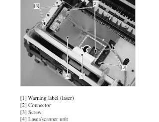
  The laser shutter cannot be opened due to the damaged claw of the cartridge cover.
Action: Replace the cartridge cover.
  Poor contact in the connectors in the laser scanner unit.
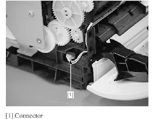
Action: Reconnect the connector J801F, J802F on the laser/scanner unit and connector J208F on the engine controller PCB.
  Defective laser/scanner unit.
Action: Turn ON the printer. Immediately after turning ON the printer, if the voltage between the connectors J208M-5 and J208M-6 on the engine controller PCB is about +5V and also the voltage between the connectors J208M-1 and J208M-4 is about +24V, replace the laser/scanner unit.
  Defective engine controller PCB.

Action: Replace the engine controller PCB.

Fixing Unit Failure
Possible Causes
  Poor contact in the connectors.
Action: Reconnect the connector J206 on the engine controller PCB.
  Broken wire or short-circuited thermistor.
Action: Turn OFF the power and remove the fixing unit from the printer. Measure the resistance between the connectors J703-1 and J703-2 on the fixing unit side. If the resistance is not within the range from about 250 kΩ to about 800 kΩ (room temperature), replace the fixing film unit.
  Broken wire of the heater or blown thermal fuse.
Action: Remove the fixing unit. Check the connectors J102F-1 and J102F-2 on the fixing unit side for continuity. If the connectors have no continuity between them, replace the fixing film unit.
  Defective engine controller PCB.
Action: Replace the engine controller PCB.

Although a paper jam has not occurred, the printer cannot enter the READY mode, outputting a “JAM” status.
Possible Causes
  Defective paper delivery sensor spring.
Action: If the spring is not installed correctly, reinstall it correctly. Or, if the spring is deformed or damaged, replace it.
  Defective paper delivery sensing lever.
Action: If the lever is not installed correctly, reinstall it correctly. Or, if the lever is deformed or damaged, replace it.
  Defective paper top sensor spring.
Action: If the spring is not installed correctly, reinstall it correctly. Or, if the spring is deformed or damaged, replace it.
  Defective paper top sensing lever.
Action: If the lever is not installed correctly, reinstall it correctly. Or, if the lever is deformed or damaged, replace it.
  Defective engine controller PCB.
Action: Replace the engine controller PCB.

Although the door is closed after installing the cartridge, the printer cannot enter the READY mode, outputting a “DOOR OPEN” status.
Possible Causes
  Damaged claw of the door switch on the connector holder.
Action: Replace the connector holder.
  Defective door open detection unit.
Action: Replace the door open detection unit.
  Defective door open detection switch / engine controller PCB.
Action: Replace the engine controller PCB.

Although paper is set in the printer, the printer cannot enter the READY mode, outputting a “PAPER OUT” status.
Possible Causes
  Defective paper out sensing lever.
Action: If the lever is not installed correctly, reinstall it correctly. Or, if the lever is deformed or damaged, replace it.
  Defective paper out sensor.
Action: Replace the paper out sensor (PS003.)
  Defective engine controller PCB.
Action: Replace the engine controller PCB.

Although the cartridge is installed in the printer, the printer cannot enter the READY mode, outputting a “NO CARTRIDGE” status.
Possible Causes
  Poor contact in the primary high-voltage contact on the engine controller PCB and cartridge contact.
Action: Clean the contacts if dirty. If the problem still remains after cleaning, or parts are deformed or damaged, replace them.
  Defective cartridge.
Action: Replace the cartridge.
  Defective engine controller PCB.
Action: Replace the engine controller PCB

HOW TO DISASSEMBLE LASER/SCANNER UNIT - DRIVE ASSEMBLY & Other Assemblies - CANON LPB1120 - LASER COPIER

$
0
0


  • Remove the rear cover, left/right cover, and upper cover.
  • To enable the disconnection of the connectors, peel off the Warning label (laser) halfway.
  • Disconnect the 2 connectors, and remove the 4 screws; then, detach the Laser/scanner unit.
[1] Do not disassemble the Laser/scanner unit; you will not be able to adjust it in the field.
[2] There is no Warning label (laser) used on the Laser/scanner unit offered as a service part. If you are replacing the assembly, remove the label from the existing assembly, and transfer it to the new assembly. Or, use the newly available Warning label. Be sure also to fully hide the connector openings from view.
DRIVE ASSEMBLY
  • Remove the rear cover and the left/right cover.
  • Remove the 2 screws and 2 screws equipped with a washer. Slide out the drive assembly slightly, and disconnect the connectors to remove the drive assembly.
FEED ASSEMBLY
  • Remove the engine controller assembly.
  • Free the 2 claws, and remove the 2 gears and the screw.

  • Push the 2 claws, and remove the bushing.
  • Remove the 2 screws, and disconnect the 2 connectors; then, remove the feed assembly.
DELIVERY ASSEMBLY
  • Open the cartridge cover.
  • Remove the boss, and remove the facedown delivery roller bushing; then, slide the face-down delivery roller to the right to detach.
  • Pull the pressure release lever to the front to release the pressure.
  • Remove the 2 screws, and slide the delivery assembly to the right to detach.
FIXING FILM UNIT
  • Remove the rear cover and the left/right cover.
  • Remove the delivery assembly.
  • With the pressure release lever shifted up, push down on the fixing pressure unit (left/right) from above; then, slide it to the rear to detach.
  • Disconnect the connector.
  • Disconnect the connector, and free the harness from the harness guide.
  • Remove the fixing film unit.

EPSON L-800 - L-801 - PRINTER - ADJUSTMENTS AFTER DISASSEMBLY or REPAIR

$
0
0
ADJUSTMENTS
Adjustment Item
Purpose
Method Outline
Tool

PG adjustment
Install the Head Nozzle surface parallel to the printing surface and set
the gap between the paper and the HeadNozzle surface to the specified value
Mechanical adjustment using the thickness gauges. Make a proper
adjustment according to the result whether the manually-moved
carriage (printhead) runs over or hits against the gauges placed on the platen.


Thickness Gauge
1.15 mm, 1.3 mm
EEPROM data copy
When the main board needs to be replaced, use this to copy adjustment values stored on the old main board to the new board. If this copy is completed successfully, all the other adjustments required after
replacing the main board are no longer be necessary

Readout the EEPROM data from the main board before removing it. Then replace the board with a new one, and load the EEPROM data to the new board


Adjustment Program
Initial setting
This must be carried out after replacing the main board to apply
settings for the target market. Whenthis function is performed, the upper limit value of the ink tube ounter is automatically set. With this function, the serial number written on the main board can be checked,
and also writing the serial number to the main board can be performed when replacing the board

Select the target market. The selected market settings are automatically
written to the main board. When writing the serial number, enter and re-enter (for confirmation)
the printer serial number, then press the input button.


Adjustment Program
Head ID input
This must be carried out after replacing the print head in order to enter the new print head ID (Head ID) that reduces variation between print heads
Enter the ID printed on the Head QR code label attached on the print head. The correction values are automatically written to the main board.


Adjustment Program
Initialize PF deterioration offse
Resets the counter to maintain paper feed accuracy which decreases due to paper dust.

Reset the counter to its default
Adjustment Program
Disenable PF deterioration offset
When reading the counter value fromthe old main board is impossible in the case of replacing the board, use this to set the counter to its
maximum value.

Set the counter to its maximum value (3000).
Adjustment Program
TOP margin adjustment
This corrects top margin of printout.
A top margin adjustment pattern is printed. Examine the lines printed
near the top edge of the printout, and enter the value for the line that is exactly 3 mm away from the top edge.

[1]Adjustment Program
[2] Ruler
Head angular adjustment
This must be carried out after replacing the print head in order to correct tilt of the print head by software
A head angular adjustment pattern is printed. Examine the printed lines and enter the value for the most straight lines

Adjustment Program
Bi-D adjustment
Corrects print start timing in bi-directional printing to improve the print quality
A Bi-D adjustment pattern is printed. Examine the patterns and enter the value for the pattern with no gap and overlap for each mode

Adjustment Program
First dot position
adjustment
Corrects left margin of printout. The print start position in the carriage moving direction is corrected by software
A first dot adjustment pattern is printed. Examine the lines printed near the left edge of the printout and enter the value for the line that is
exactly 5 mm away from the left edge


[1]Adjustment Program
[2] Ruler
PW adjustment
This adjustment is made to correct the mounting position of the PW Sensor on a software basis to adjust the detection position and Nozzle
position dispersion.
A PW adjustment pattern is printed. Examine the printout patterns and enter the value for the line that is exactly 5mm away from the paper edge for each of the left, right, top and bottom

Adjustment Program
Ruler.
PF adjustment
Corrects variations in paper feed accuracy when using the Microweave
to achieve higher print quality.
A PF adjustment pattern is printed. Examine the printout patterns and select the value for the best pattern. The correction value is registered.


Adjustment Program
BRS/PFP adjustment
This adjustment is made to ensure high print quality at high print speed.
Print the adjustment pattern to be scanned by a specified scanner.
According to the scanned result, a correction value is automatically
calculated and stored into the serial flash ROM on the main board. The correction value isapplied when printing in the corresponding
mode. For some scanners, two PFP base scales are required

[1] Specified Scanner
[2]  PFP base scale
CR motor heat protection control
This must be carried out for efficient heat control of the CR motor. Electrical variation of the motor and the power supply board are measured to acquire correction values for them
Select the parts that you replaced. The correction values are
automatically written to the main board.
Adjustment Program

MAINTENANCE ITEMS
Maintenance Item
Purpose
Method Outline
Tool

Head cleaning
This function is used to execute Cleaning efficiently when ink is not delivered from the Head properly, e.g. dot missing
The cleaning can be selected from the normal cleaning or the power cleaning. Whether to reflect the discharged ink amount to the waste ink pad counter or not can also be selected as an option. The head cleaning is
performed automatically. After the cleaning, print a nozzle check pattern
to check if all nozzles are firing ink properly.

Adjustment Program
Maintenance counter
The printer causes a maintenance error when the maintenance counter (for the Waste Ink Tray, Waste Ink Pad Lower) reaches its maximum.
Use this to reset the counter after replacing the Waste Ink Pad and Waste
Ink Pad Lower, and use this to reset the ink tube counter when replacing the Ink Supply Tube. If you find the counter is close to the maximum
during servicing, carry out the pad replacement and the counter reset to
avoid the printer returned from the user due to the maintenance error

Select the replaced parts, and reset the corresponding counters.
Adjustment Program
Ink charge
This function is used to charge ink to the components composing the ink
path such as Print head after replacing them
The ink charge can be selected from the charge to Print head only or the charge through Ink Tube, Adapter to Print head. Whether to reflect the discharged ink amount to the waste ink pad counter or not can also be
selected as an option.
Select the range to charge ink and options, and then press the execute
button to execute the ink charge to the selected range automatically. After ink charge, print a nozzle check pattern to check if all nozzles are firing ink properly.

Adjustment Program
Small ink counter reset
When an ink out error occurs even though some ink is still in the Ink Supply Tank Assy (in the case when the ink counter in the printer and the actual ink remaining amount do not match), this function can decrease the ink counter (resetting the counter partially) to adjust the counter with the actual ink remaining amount
If the execute button is pressed, the ink counter value is automatically
set. But if no ink out error is occurring, the message which says the function cannot be executed appears and no reset will be made.
Adjustment Program
Final check pattern
print
A4 size
US Letter size
Use this to check if the all adjustments have been properly made.

The all adjustment patterns are printed automatically.
EEPROM dump
Use this to readout the EEPROM data for analysis

The all EEPROM data is automatically readout and stored as a file

HOW TO ENTER SERVICE MODE - QLS 14TS1020 [CHINA] – MODEL (3P68S-Chassis) – STR-W6553A MAIN POWER REGULATOR SCHEMATIC

$
0
0

SERVICE MODE
  • Enter "factory service mode": Press "MENU","Q.VIEW" and "PP" in turn.
  • Enter "design service mode" : After entering "factory service mode", select "SC" item, then press "8","9"keys. (Normally "design service mode is not needed for production line.)
  • Exit service mode: Press "DISPLAY" key to exit service mode.
Adjustment:
  • In service mode, pressing digital keys directly can enter the corresponding page, pressing "MENU "key can enter the next page, pressing "SCAN" key can enter previous page.
  • Pressing "UP" and" DOWN" keys can select the items to adjust, pressing" LEFT" and" RIGHT" keys can adjust the data values.
BUS OPEN MODE
In service mode, pressing "MUTE" key can enter "BUS OPEN" mode, which is useful for white balance adjustment using AUTO WHITE BALANCE EQUIPMENT or mass data written into EEPROM. IC. Pressing "MUTE" key again can exit "BUS OPEN" mode.
FACTORY MODE
In service mode, pressing "PP" key can enter "FACTORY MODE", which is useful for aging in production lines.  Pressing "PP" key again can exit "FACTORY MODE".
AGING MODE
  • When enter into factory mode state, pressing P.P. key will be permitted to enter Aging of machine mode.
  • Press "8"key and "9"key one by one button exit aging mode.
POWER SUPPLY SCHEMATIC
CLICK ON SCHEMATIC TO ZOOM IN

MEMOREX MT-1098 - POWER CONTROL [SMPS] - FA7610CP (Power control)Schematic - [Universal Remote control Setup Codes]

$
0
0

POWER SCHEMATIC
Click on Schematic to Zoom In
Set-up codes
GE universal remote: 000, 001, 004, 006, 009, 031, 046, 049, 051, 082, 083, 135, 162, 268, 310 {0004 0009 0049 0051 0135 0031 0000 0268 0310 0001}
RCA RCR 311W: 1004, 1006, 1013, 1019, 1047, 1054, 1163, 1167, 1205, 1207, 1213, 1230
RCA RCR 312W: 10154, 10463, 10150, 10178, 10016
6 in 1 Super remote: 014,022,062,095,096
Comcast on demand remote control: 0154, 0250, 0463, 0150, 0178, 0179, 0016
Philips SRP-3004 remote control: 1800.

AKIRA 14AZ9 - TV MAIN POWER [SMPS] SCHEMATIC [Circuit Diagram] - FULL SCHEMATIC

$
0
0

SMPS SCHEMATIC


CLICK ON SCHEMATIC TO ZOOM IN

BENQ - S-72 LAPTOP - HOW TO REPLACE RAM MODULE & HARD DISC DRIVE

$
0
0

RAM MODULE REMOVAL
Remove 2 screws and RAM door can be removed.
Release the RAM catches on both sides. RAM module can be removed.

HDD REMOVAL
Remove 2 screws and HDD door can be removed.
Pull the HDD carefully with black tape.


EPSON L800 - L801 - COLOR INKJET PRINTER - ERROR CODES DISPLAY

$
0
0

ERROR CODES
CLICK ON TABLES TO ZOOM IN

HOW TO REMOVE THE PRINTER MECHANISM - EPSON L800 - EPSON L801 - COLOR INKJET PRINTER

$
0
0


PRINTER MECHANISM REMOVAL
Be careful of the four sharp edges shown in the figure below when assembling or reassembling.
Printer Mechanism Handling Precaution
When lifting the printer, hold parts shown in the figure below to prevent the frame from deforming.
  • Do not touch the PF Scale with bare hands or damage it.
  • If the Printer Mechanism is tilted leftward about 15°, the PF Scale hits against the desk surface and can break. After removing the Printer Mechanism, take extra care to protect the PF Scale.
  • When removing the Waste Ink Tube, take care not to contaminate the printer and surroundings with ink.
  • Extra care must be exercised not to scratch or damage the Waste Ink Tube.
Pull out the Waste Ink Tube by hand.
  • Release the Waste Ink Tube from the groove of the Waste Ink Tray.
  • Release the CR Motor Cable from the two ribs of the Waste Ink Tray
  • Disconnect the connector of the CDR Guide Sensor.
  • Remove the five screws and remove the Printer Mechanism.
Screw : C.B.P.(P2) M3x8 (tightening torque:5-7 kgf.cm) (The numbers shown in the figure indicate the order of tightening the screws.)
When installing the Printer Mechanism, be careful of the following:
  • Wipe off any ink on the joint portion of the Waste Ink Tube before reconnecting the tube. Ink on the joint portion makes the tube likely to get disconnected.
  • Insert the Waste Ink Tube over the tube of the Waste Ink Tray until the top end of the Waste Ink Tube contacts with the rib.
  • Match the positioning holes with guide pins (two pairs) shown.
  • Tighten the screws in the order given.
  • Make sure the Waste Ink Tube or cables are not pinched between the Printer Mechanism and the Housing Lower.
  • Route the CDR Guide Sensor Cable through the opening.

HOW TO REMOVE PRINT-HEAD - EPSON L800 - EPSON L801 - COLOR INKJET PRINTER

$
0
0

HOW TO UNLOCK THE CARTRIDGE
Move the CR Unit to the center, open the Cartridge Cover and remove all Ink Cartridges.
While disengaging the hook of the Head FFC Cover with a flat-head screwdriver, slide the Head FFC Cover downward and remove it.
While disengaging the hook of the Head FFC Cover Inner with a flathead screwdriver, slide the Head FFC Cover Inner upward and remove it.
Using the special tool disengage the hook A of the Holder Contact on the left back of the Carriage Unit.
Using the special tool disengage the hook B of the Holder Contact on the right back of the Carriage Unit.
Slide the Holder Contact upward and remove the Holder Contact.
Take extra care not to spill ink and contaminate the surroundings.
Be extremely careful not to touch the nozzle surface, the ink supply needles and the Head Cover, otherwise the nozzles may get clogged.
Remove the three screws and remove the Printhead.
Screw : C.B.P. M2.6x8 (tightening torque: 3-5 kgf.cm)
(The numbers shown in the figure indicate the order of tightening the screws.)
Remove the two Head FFCs from the connectors on the back, and remove the Printhead.
{Special Tool}

EPSON L-800 & EPSON L-801 - COLOR LASER PRINTER - INK SUPPLY TANK ASSEMBLY REMOVAL PROCEDURE

$
0
0


INK SUPPLY TANK ASSEMBLY
  • Be careful not to damage or peel off the film of the Ink Supply Tank.
  • Be careful about how to place the Ink Supply Tank Assy in order to prevent printing failure from occurring.
Ink Supply Tank Tube Assy
  • Route the Ink Supply Tank Tubes with the red lines facing upward (as viewed when the Ink Supply Tank Assy is installed on the printer) and connect them to the Ink Supply Tank Assy without any twist.
  • When connecting the Ink Supply Tank Tubes to the Ink Supply Tank, confirm the color indicated on the film of the Ink Supply Tank, and take care not to connect them with wrong joints.
  • When connecting the Ink Supply Tank Tubes to the Ink Supply Tank, insert the tubes to the full and make sure the gaps between the end of tubes and the tank are 0.5 mm long or less.

  • Make sure the red lines of the Ink Supply Tank Tube and Ink Supply Tube facing upward.
  • When attaching the Joint, align the cutout of the Joint with the rib of the Cover Case.
  • Make sure the gaps between the end of Ink Supply Tank Tubes or Ink Supply Tubes and the Joint are 0.5 mm long or less.
COVER CASE
Remove the screw (x1).
Lift the Cover Case slightly to release the dowels (x2) on the bottom of the Cover Case.
Rotate the Cover Case in the direction of the arrow (1) to avoid the section A and B of the Cover Case from bumping against the Front Frame.
Remove the Cover Case in the direction ofthe arrow (2) while avoiding the section C of the Cover Case from bumping against the Front Frame.
PF Scale Cover / PF Scale Sheet.
  • Wipe off the area on the Main Frame shown above using a cloth moistened with alcohol.
  • Align the PF Scale Cover with the rib of the Front Paper Guide Assy, and attach the PF Scale Cover.
  • Align the screw holes of the PF Scale Cover and Front Paper Guide Assy, and secure the PF Scale Cover with the screw (x1).
  • After the alcohol dried out completely, insert the section A of the PF Scale Sheet into the groove of the Front Paper Guide Assy, and then attach it with double-sided tape.

  • Insert the section A of the Tube Guide Sheet Sub into the hole 1 of the Tube Guide Sheet from the bottom.
  • Insert the section A of the Tube Guide Sheet Sub into the hole 2 of the Tube Guide Sheet from the top.
  • When attaching the Tube Guide Sheet to the Tube Guide, while keeping the Tube Guide Sheet Sub attached on the Tube Guide Sheet, align the holes of the Tube Guide Sheet with the protrusions of the Tube Guide.

HOW TO REMOVE - Ink Supply Tube Assy & Adapter Cover - EPSON L800 & EPSON L801 - COLOR PRINTER

$
0
0

INK SUPPLY UNIT ASSEMBLY
  • Place the Ink Supply Tube onto the Tube Guide Sheet with its Tube Porous Pad side down.
  • Connect the Ink Supply Tubes (x6) to the Joint.
  • Insert the section A of the Tube Guide Sheet Sub from the top into the hole of the Tube Guide Sheet Sub to secure it.
  • Attach the Tube Holders (x3) and secure them with the screws in the order shown in the figure.
  • Hold the Ink Supply Tube by the Adapter side and flip it over as shown in the figure, then put a marking on the bottom side of the Ink Supply Tube 70 mm from the Tube Clamp nearest to the Adapter.
  • Connect the Ink Supply Tube to the Adapter, and install the Adapter to the CR Unit.
  • Route the Ink Supply Tubes through the grooves of the CR Unit, and align the markings on the Ink Supply Tubes with the edge of the grooves as shown in the figure.
ADAPTER COVER
  • Attach the Tube Guide Sheet to the Adapter Cover.
  • Insert the dowels (x2) of the Adapter Cover into the holes (x2) of the CR Unit and engage the hook of the Adapter Cover to the CR Unit.
  • Make sure no Ink Supply Tubes are caught, then secure the Adapter Cover with the screw (x1).
  • After installing the Adapter Cover to the CR Unit, move the CR Unit from side to side while holding the Timing Belt to make sure that the Ink Supply Tube Assy does not apply extra load of the CR Unit movement.
CLICK ON PICTURES TO ZOOM IN

Be careful not to damage or peel off the film of the Adapter.
Use a precision screwdriver when releasing the hooks of the Adapter.
When connecting the Ink Supply Tubes to the Adapter, make sure the red lines on the Ink
Supply Tubes are facing upward as shown in the figure above.

DAYTEK - LC1508NT – LC1521NT – LC2018NT - HOW TO ENTER SERVICE MODE [Fcactory Mode] - Universal Remote Control Set-up Codes

$
0
0


SERVICE MODE
  • Using the remote control, press Menu button once first.
  • Then press PRE.CH (or named RECALL) button five times, and you can see manufacture menu on the LCD panel.

  • Press the channel  +/- button to selection the sub menu of factory menu (including F, E, UOCIII, RGBTemp, Temp, and press the Vol + to enter the sub menu and setting the value.
To exit the factory menu
  • Press the MUTE button again and again or turn off the TV, it can exit the Factory Menu.
UNIVERSAL REMOTE CONTROL SET-UP CODES
1051 1310 1121 1263

DURABAND - T6605VF – T6705VF – TV/VCR COMBO - VCR MECHANISM SERVCE

$
0
0

VCR MECHANISM ALIGNMENT
Method for Manual Tape Loading/Unloading
To load a cassette tape manually:
  • Disconnect the AC plug.
  • Remove the Top Case and Front Assembly.
  • Insert a cassette tape. Though the tape will not be automatically loaded, make sure that the cassette tape is all the way in at the inlet of the Cassette Holder. To confirm this, lightly push the cassette tape further in and see if the tape comes back out, by a spring motion, just as much as you have pushed in.
  • Turn the LDG Belt in the appropriate direction shown in Fig for a minute or two to complete this task.
To unload a cassette tape manually:
  • Disconnect the AC plug.
  • Remove the Top Case and Front Assembly.
  • Make sure that the Moving guide preparations are in the Eject Position.
  • Turn the LDG Belt in the appropriate direction shown in Fig. until the Moving guide preparations come to the Eject Position. Stop turning when the preparations begin clicking or cannot be moved further. However, the tape will be left wound around the cylinder.
  • Turn the LDG Belt in the appropriate direction continuously, and the cassette tape will be ejected.  Allow a minute or two to complete this task.
Method to place the Cassette Holder in the tape-loaded position without a cassette tape
  • Disconnect the AC Plug.
  • Remove the Top Case and Front Assembly.
  • Turn the LDG Belt in the appropriate direction shown in Fig. M1. Release the locking tabs shown in Fig. and continue turning the LDG Belt until the Cassette Holder comes to the tape-loaded position. Allow a minute or two to complete this task.


CCE SR-200 - AMPLI-TUNER - SCHEMATIC DIAGRAM [Click on Schematic to Zoom In]

SONY PLAYSTATION-3 - SCHEMATIC DIAGRAM [Click on Schematic to Zoom In]

SONY TRINITRON - CTV-25 [BA-4 Chassis] - SELF DIAGNOSIS - BLINKING CODES & DETAILS

$
0
0


SELF DIAGNOSTIC ON-SCREEN DISPLAY
   A dormant intermittent problem is difficult to detect. The BA-4 chassis Control Tuning System IC001 has a program to record the number of times the TV has failed in the first three categories listed above. This information can be accessed and displayed on the TV screen as long as the set remains plugged in.
SELF DIAGNOSTIC ACCESS
With the set OFF, aim the remote at the TV and press the following remote buttons in this sequence:
1. Display
2. 5
3. Volume Down [ – ]
4. Power On.
   The TV will power ON and display the self-diagnostic page. This self-diagnostic display will overlay the TV or video picture.
   At the left of the self-diagnostic TV screen display are the numbers 2, 4 and 5. These represent the number of times the Timer/Standby light was blinking. The numbers 3 and 101 are not used (N/A).  The column on the right side shows the number of failures that have occurred since the program was reset. Up to 99 failures can be recorded.  Although the self-diagnostic page will display the number of times a failure has occurred, it will not be able to tell you exactly where the problem is, only that it exists.
Self-Diagnostic is new in the series BA-4 TV chassis. It uses a blinking light or OSD to notify you if there is a failure caused by the following:
1. Excessive fly-back current or amplitude;
2. No Vertical sweep; or
3. No green automatic white balancing signal.
TIMER/STANDBY LIGHT
   The number of times the Timer/Standby light blinks indicates what failure the Control Tuning System Microprocessor IC001 detects. IC001 will shut off or blank the TV set to protect itself. The Standby/Timer light will continue to blink as long as the TV is plugged into AC power.
   The number of times the TV has failed is held in memory. As long as there is failure information present, the standby light will blink when the set is tuned OFF.  Unplugging the TV set will clear the memory information and stop the blinking.
FAILURE CHECK LIST
Some of the reasons for the failure could be in this checklist.
When the problem is intermittent, you will have to probe further by monitoring the horizontal output transistor temperature and the TV’s current consumption to see if it is high, vibrate and possibly “bake” the set to force the intermittent failure to reveal itself.
MEMORY CLEAR
   Unplugging the TV from AC power resets the stored failure information and stops the blinking light. The memory is cleared once standby +5Vdc is removed from the Control Tuning System Microprocessor IC001. It can also be manually cleared by first pressing 8 and then pressing ENTER while you are in the self-diagnostic mode.
  1. Unplug the TV from AC. à Removing AC power clears the memory at any time.
  2. From the remote control. à Press buttons: 8,then press ENTER.
Self Diagnostic Exit:
Shutting off power to the set retains the memory information and allows you to return to the TV picture.
SELF DIAGNOSTIC CIRCUIT
   The self-diagnostic program is contained in the Control Tuning System IC001. The number of problems is detected by the program is stored in IC001. This number remains in IC001’s resident memory as long as the TV remains plugged into AC and is not manually cleared.
When the TV set is turned ON, IC001 monitors three TV conditions using two inputs at pins 37 and 17. These TV conditions are:
1. Vertical Failure - In normal operation, Vertical Output IC541’s “Ref” pin 3 outputs a 30Vp-p pulse (1msec pulse width). This voltage is reduced by R549 and clamped to no higher than 5Vp-p by D001.  These vertical pulses from IC541/pin 3 are monitored by Control Tuning System IC001 at pin 17.  A vertical drive failure causes no pulses to be generated. If these vertical pulses are lost for two seconds, IC001 will turn OFF the TV to prevent the vertical deflection failure from damaging the CRT. However, the front panel Timer/Standby light continues to blink four times, pauses and repeats, even though the set is OFF.
2. Excessive Current Demand/Excessive FBT pulse amplitude – Y/C Jungle IC301 monitors both of these conditions at input pin 18. Normally there are horizontal pulses applied to IC301/pin 18 when the TV is ON.  When there is excessive current being drawn by the FBT or Horizontal Output Transistor, the horizontal pulses are grounded out. The Y/C Jungle IC301 detects this loss from pin 18 almost immediately and sends data from IC301/pin 35 to IC001/pin 37 (even in normal operation, there is always data on this line). IC001 shuts OFF the TV to protect itself. The Timer/Standby light blinks two times, pauses and repeats to indicate the failure.  If flyback (FBT) pulses were abnormally high, perhaps as a result of an open resonate capacitor (C508 in this set), the TV would similarly shut down. Higher than normal FBT pulses result in a high DC voltage that also grounds the horizontal pulses at IC301/pin 18. The loss of horizontal pulses is detected and data is sent from IC301/pin 35 to IC001/pin 37 for the TV to shut OFF. The Timer/Standby light continues to blink two times, pauses and repeats after the failure.
3. White Balance Failure – Jungle IC301 initiates CRT drive and monitors CRT cathode current at pin 21. The amplitude of the three IK pulses that return to IC301/pin 21 represent the level of red, green and blue CRT cathode emissions. Their amplitudes are used to white balance the picture while the TV is ON.
This IK circuit is designed to look for three IK pulses returned from the picture tube. If IC301 detects a missing IK pulse within two seconds after the set is turned ON, the video is blanked (muted). The two seconds allow time for the picture tube to warm up. This blanking state is relayed as data from IC301/pin 35 to C001/pin 37. IC001 causes the Timer/Standby light to blink five times, pause and repeat. The set remains ON during this video failure, so the sound is still present.
   When there are multiple failures, the two blinking light failure has a higher priority over the four blinking light failure. By the same logic, the four blinking light failure has a greater priority than the five blinking light failure. For example, if multiple failures caused all of the two, four and five blinking light failures to be stored in memory, the Timer/Standby light would blink two times, pause and repeat when the TV shut down. The number of failures has nothing to do with how many times the light blinks.
Display
   By using the TV’s remote control, you can access this failure information stored in memory. Once IC001 receives the self-diagnostic access command at pin 12, IC001 powers ON the TV. The failure information from IC001 is sent to the Jungle IC301 as On Screen Display (OSD) video levels.  A “OSD Blk” signal accompanies the OSD video levels from IC001 into IC301. This analog input voltage at Jungle IC301/pin 29 is used to darken (blank) the main RGB picture signal at the instant the OSD character is to appear and enable the OSD. Since IC301/pin 29 is an analog input, 0Vdc input leaves the main picture at normal brightness. 2Vdc input reduces the picture to half brightness and 5Vdc blanks or mutes the picture.
   While the main picture is at half brightness, the OSD self-diagnostic page is displayed at normal brightness and appears as an overlay to the main picture.

HOW TO TROUBLESHOOT - SONY TRINITRON CTV-25 [BA-4 Chassis TVs] - Protection circuits details

$
0
0

TROUBLESHOOTING [Protection]
   A loss of data, vertical drive, flyback generator signal or +13Vdc power will cause the protection circuit to shut OFF the TV. The 30Vp-p retrace pulse from IC541/pin 3 is used as an indication of vertical output operation. This pulse is reduced to 5Vp-p and monitored by Micro IC001/pin 17. After two seconds of missing pulses, IC001 will turn OFF the TV set and blink the Timer light four times.
Troubleshooting
   When the TV is shutdown and the Timer/Standby light blinks four times, the problem is in the vertical or horizontal section. Start the TV by pressing the Power button. You have two seconds to identify the missing signal with your scope or voltmeter before the TV shuts down again.  Here is a general checklist of items that will cause the TV to shutdown:
Some causes for the Timer/Standby light to blink four times and repeat
  1. No Data/Clock input (IC301/pin 34, 35). This causes NO IC301/pins 13-14 drive output.
  2. Missing positive or negative 13 voltage to power IC541 at pins 2 or 4. This voltage comes from the FBT.
  3. Loss of either or both vertical drive signals from IC301/pins 13 and/or 14.
  4. Loss of horizontal drive resulting in no FBT voltages.
  5. No fbt/boost output from IC541/pin 3

Automatic Brightness Limiting (ABL)
   The purpose of this circuit is to prevent sudden bright scenes from shortening the life of the picture tube. It does this automatically by monitoring the picture tube’s current and then using this voltage to limit the brightness of the picture.  The flyback transformer T504 (secondary) supplies the picture tube’s high voltage. The ground end of the secondary at T504/pin 11 is current limited by a 100k ohm resistor, R535. As the picture gets brighter, the high voltage current increases, causing a voltage drop across R535. This ABL voltage decreases with increasing brightness.
   Voltage divider R533, R534 and R532 bias this ABL line with a positive voltage that is applied to Jungle IC301/pin 3. A lower ABL voltage decreases the level and gain of the RGB waveform. This is how ABL section uses the Jungle IC to keep the brightness within a reasonable operating range.
OCP Protection
   One part of the protection circuit is shown here in block form. The over current Protection (OCP) stage shuts OFF the TV during a fault. Q571 is used to monitor the current flowing through the FBT and horizontal output transistor. If the current becomes excessive, Q571 conducts, grounding out the DC voltage from the Jungle IC301/pin 18. This ground causes IC301/pin 34 to send data to Micro IC001/pin 37. The data instructs IC001 to shut OFF the TV, allowing the horizontal output transistor to cool down.
Vertical Output Failure
  Pulses from the vertical output IC are monitored for activity by IC001.  Two signals are output when the vertical output stage is receiving the drive signal and amplifying. The main drive signal goes to the vertical deflection yoke. The other signal is made inside the vertical Output IC541’s flyback generator and output pin 3. At pin 3 is a 30Vp-p pulse that is reduced by R549 and limited by zener diode D001 to 5Vp-p. IC001/pin 17 receives and monitors this 5-volt vertical pulse to prove the Vertical stage is operating.
If IC001 detects a loss of these vertical flyback pulses for two seconds, IC001 will turn the TV OFF. As part of IC001’s diagnostic program, after the set is turned OFF (but not unplugged), the Timer/Standby light will blink four times, pause and repeat. This indicates the problem is a loss of vertical signal.  Unfortunately, +13Vdc that powers the vertical IC541 comes from the horizontal stage (FBT). Therefore, a horizontal failure will also cause the light to blink four times, pause and repeat.
Excessive FBT Voltage
   An open safety capacitor C508 or high B+ voltage can cause the flyback transformer (FBT) to produce an undesirably high secondary voltage.  The FBT’s secondary voltage at T504/pin 7 is monitored for excessive signal level.  This stage consists of T504, D574, IC521, Q300, IC301 and IC001.  Flyback pulses are rectified and compared to a reference voltage to determine if they are excessive. The 120Vp-p T504/pin 7 pluses are rectified by D574 into 109.2Vdc. This voltage is reduced further to 8.76Vdc by voltage divider resistors R583, R582 and R584 and applied to the + input of comparator IC521/pin 5. As long as the voltage at pin 5 is no higher than the 9.7Vdc at the negative input pin 6, the output of IC521/pin 7 will remain LOW (1.34Vdc).  The Jungle IC detects the comparator output. The LOW from comparator IC521/pin 7 is applied to Q300/base, keeping it OFF as if it were not in the circuit. This allows the horizontal pulses from Q502/collector and the internal voltage of 3.4Vdc to remain at Jungle IC301/pin 18 for normal operation.
   When the FBT voltage is excessive, the TV is required to shutdown. An excessive FBT voltage level will cause IC521/pin 7 to output a HIGH, which will turn ON Q300. When Q300 saturates, the 3.4volts from IC301/pin 18 are grounded. This ground immediately causes shutdown data to output IC301/pin 35 to the Micro. The Micro receives this command and produces a HIGH at pin 6 to shut off the TV. After the TV is shut OFF, the Timer/Standby light blinks two times, pauses and repeats for as long as the set is plugged into 120Vac.
Excessive B+ current Failure
Leakage in the Horizontal output transistor Q502, shorts in flyback transformer T504 or a short in a secondary winding would draw excessive current from the B+ line. Excessive current drain will cause the TV to shut down, allowing itself to cool off.  Components involved in this stage are R571, Q571, Q300, IC301 and IC001. All the current from the B+ source flows through resistor R571.  Transistor Q571’s emitter-base junction is essentially placed across this resistor. Resistors R574, R575, R572, and R573 pre-bias Q571. C571 across Q571/b-e prevents rapid scene changes from turning Q571 ON and triggering the protection circuit.  If R571 drops sufficient voltage to turn ON Q571, its conduction will apply a positive voltage through D581 into the base of Q300, turning it ON as well. When Q300 turns ON, the 3.4Vdc from IC301/pin 18 is grounded out. This causes IC301 to send shutdown data from pin 34 to IC001/pin 37. IC001 responds by shutting OFF the TV set when pin 6 is brought HIGH. After the TV is shutdown, the Timer/Standby light blinks two times, pauses and repeatsfor as long as the set is plugged into 120Vac.
During a failure that causes the TV to shutdown or go into blanking, the Timer / Standby light D002 blinks, pauses and blinks again. The number of times it blinks identifies the defective stage:

Standby Light Blinks
TV Symptom
Problem Circuits

2 times, pauses and repeats
Shutdown. TV powers OFF.
Excessive B+ current
demand or high FBT pulse amplitudes.

4 times, pauses and repeats
Set Turns OFF
Vertical Failure (may also be Horizontal Failure since the vertical IC is powered by the
FBT.)

5 times, pauses and repeats.
1.  Raster, but no video
2. Sound OK
White balance failure, weak picture tube or Low G2 voltage.

Continues to blink once a second
No or defective Jungle
IC301 communications.
No reply from an IC (data bus is busy -grounded or held HIGH)


Timer / Standby light – blinks two times
The TV is shutting down because there is an excessive current drawn by the Horizontal Output Transformer or Transistor. After checking for shorts in these stages, test the protection trip circuitry.
Testing the Protection Circuitry
  • Locate Q300/base. The collector lead of this surface mount transistor is by itself. If the collector is pointed up, the base lead is at the left.
  • Monitor the DC voltage with a DVM (peak reading is preferred).
  • Turn ON the TV.

  1. The normal voltage should be less than 0.5Vdc. If it is less than 0.5Vdc before the TV turns OFF again, there is a problem in the protection circuit at Q300 or IC301.  Test Q300 for leakage or replace.  Move your DVM probe to IC301/pin 18 and turn ON the TV. If this voltage stays below 2Vdc, Q300 is leaky. If above 2Vdc, IC301 may be defective.
  2. If the voltage at Q300’s base is HIGHER than 0.5Vdc, the problem may be in IC521, Q571, or in the circuitry.
  3. Place your DVM at IC521/pin 7 and turn ON the TV. The normal voltage should be less than 2Vdc. If it is higher, the problem is around IC521 or there is excessive FBT voltage from an open safety capacitor (C508) or high B+ voltage.  Reduce the AC voltage and monitor the voltages at IC521/pins 5 &6. The voltage at IC521/pin 6 is fixed at the D573 zener voltage plus 0.6V (D572). The normal voltage at pin 5 should never exceed 10Vdc.  If the voltage at IC521/pin 5 is HIGHER than 10Vdc, the problem is in the circuit’s safety capacitor or high B+ voltage.  If the voltage at IC521/pin 5 is Lower than 10Vdc, the problem is about IC521.
  4. If none of the voltages around IC521 were high, the problem must be around Q571, a defective horizontal output transistor or transformer.
  5. Place your DVM at Q571/collector. Turn the TV ON. This voltage should not rise above 10Vdc.  If this voltage is HIGH, suspect Q571, R571 and other resistors in the area.  If these protection parts test OK, there is a heavy current demand on the B+ line. The problem may be a short at the FBT secondary windings.

Timer / Standby light – blinks four times
A vertical deflection failure or horizontal drive failure is indicated.
Test the horizontal section by using one of these tricks:
* Place your scope probe by the FBT and turn ON the TV. You will see the horizontal signal if the drive path from the Jungle IC to the FBT is OK
* Listening to the frying sound at the yoke is another indicator of horizontal signal arriving at the yoke
  • Test the vertical stage by using the scope probe to monitor the vertical drive signal and the DVM to measure the positive and negative supply voltages to the vertical IC541 at turn ON.
  • Test the Protection circuitry by placing your scope lead at the Vertical Output IC541/pin 3. You should see a 30Vp-p pulse there. If it is present, this pulse is not getting to IC001/pin 17. Replace zener D001 if shorted.

Timer / Standby light – blinks five times
  This failure is caused by a problem in the video output IK circuit. Turning up the screen control will let you see light on the screen so you can make an evaluation of the problem.

SONY VAIO - PCG-SR33 - PCG-SR33K - PCG-SR27 - PCG-SR27K - PARTS LOCATION & DISASSEMBLE PROCEDURE

$
0
0


MAIN ELECTRICAL PARTS LOCATION
KEYBOARD UNIT & PALM ASSEMBLY REMOVAL
TOUCH-PAD, RIGHT SPEAKER & SWX-61 BOARD REMOVAL
{Click on pictures to Zoom In}
HARD DISC DRIVE REMOVAL
LEFT SPEAKER & IFX-125 BOARD REMOVAL
FRAME ASSEMBLY, DC FAN REMOVAL
MAIN BOARD ASSEMBLY REMOVAL
MBX-44 Board, IFX-124 Board, DDC-3 Board, V/L Rechargeable Battery removal
CNX-107 BOARD REMOVAL
DISPLAY ASSEMBLY REMOVAL
LCD SECTION

Viewing all 2033 articles
Browse latest View live


<script src="https://jsc.adskeeper.com/r/s/rssing.com.1596347.js" async> </script>