Quantcast
Channel: Electro help
Viewing all 2033 articles
Browse latest View live

LG - BS254 – BX254 – BX324 - DATA PROJECTOR - HOW TO REMOVE OPTICAL ENGINE_FAN & I/O PANEL

$
0
0


REMOVING THE OPTICAL ENGINE
  • Remove the two screws (S01) and take out the Engine FAN.
  • Remove the three screws and careful when the wire when you assembly.
REMOVING POWER AND LVPS BOARD
  • Remove the three screws.
  • Review the Power board.
  • Remove the two screws and careful the wire when assembly.
{CLICK ON PICTURES TO ZOOM IN}
Removing the Lamp shield/Lamp Fan/Therm/Switch
  • Remove the three screws.
  • Remove the two screws.
  • Review the two LAMP FANS
  • Remove the two screws.
Removing the ADJ ASSY / Review Bottom case.


HOW TO UPGRADE FLASH - LG - BS254_LG-BX254_ LG-BX324 - DLP PROJECTOR

$
0
0


UPGRADE PROCEDURE
System Requirement
IBM compatible PC (Desk Top).
Windows XP-SP2 operating system.
Attention: This utility is for DLP DDP2000/2230/243x serial projectors.
  • Install “DLP Composer Lite” to PC
  • Run the “DLP Composer Lite v10.0 Setup.exe”.  
  • The following pictures are illustrating the process of the Driver installation.
  • Click on the “Next” button to continue.
  • Click on the “I accept agree to be bound by all the terms and conditions of this License Agreement” point to continue.
  • Click on the “Next” button to continue.
  • Click on the “Next” button to continue.
  • The default installation direction is C:\Program Files\DLP Composer 10.0

Click on the “Browse” button to change the default directory for saving the drive file somewhere else.
or
Click on the “Back” button to return to the previous page.
or
Click on the “Cancel” button to cancel the installation.
or
Click on the “Next” button to continue.
Click on the “Back” button to return to the previous page.
or
Click on the “Next” button to continue or
Click on the “Cancel” button to cancel the installation.
Wait for the installation to complete.
Installation Completed:
Click on the “Finish” button with the Installation Completed.
Replicate the program file “FlashDeviceParameters.txt” to PC under path: “C:\Program Files\DLP Composer Lite 10.0\”

LG - BS254_BX254_BX324 - DATA PROJECTOR - FLASH-TOOL FIRMWARE - HOW TO DOWNLOAD & UPGRADE

$
0
0


FLASH-TOOL FIRMWARE
System Requirement
IBM compatible PC (Desk Top).
Windows XP-SP2 operating system.
  • Launch the “DLP Composer Lite v10.0” from installed shortcut at  Program > DLP Composer(TM) Lite 10.0 > DLP Composer(TM) Lite 10.0.exe
While executed, the window shall appear as the following picture.
  • Click on the “Edit” button to continue to the“DLP Composer Preferences” page.
  • Turn on the projector, press the” MENU “button on the keypad or IR controller.
  • Then select “Installation II”,then press“ Down ”button and select “ Advance ” item.
  • Press “Down” button on the keypad to select “Low Power Mode” item,  Press the “Enter” button to set function to “Off”.
  • Turn off the projector.
  • Make sure that the RS-232 cable is firmly connected between projector and computer.
  • Using the remote control and press <Down>, <Up>, <Right>, <Up> keys in sequence using buttons.
  • The “Power LED” shall blink twice and the download mode will be enabled.
  • Click on the “Communications” button to continue to the “Communications” page.
  • Choose the “Serial Port” item of Projector Interface.
  • Select “COM1: (In-use)” item.
  • Click on the “Configure” button to continue to the” Serial Port Configuration” page.
Set Baud Rate = “115200”
Set CTS = “Disable”
Click on the “OK” button to continue.
  • Choose the “Flash Loader”item of DLP Composer Lite.
  • On the Flash Image File: Press “Browse” button to locate the new firmware which can be downloaded from PC. (For example file name: DP2404_LG_DVT03_20091119.img).  
  • Select the desired *.img file by either double clicking the file, or pressing the “Open” button.
  • Press the “Start” button to update the flash with the chosen firmware.
  • A warning message box will appear for confirmation. Press [Y] to continue.
When the last warning message box appears, this is the last chance to cancel the update. 
Press “Confirm” button to start the firmware update.

TCL - NX56LA CHASIS TVs - HOW TO ENTER SERVICE MODE - Schematic Diagram - NCP1337 [Power Control] – SK2996 [FET Power Switching] – STV8172A[Vert-output] – 63MPF[FET-Horizontal Output Transistor] - Universal Remote Control Codes

$
0
0

TO ENTER SERVICE MODE
Method one
  • Switch on the TV set.
  • Press the “MENU” key on RC to show the “PICTURE” OSD menu.
  • Move the cursor to “Contrast” item then press the “9”, “7”, “3”, “5” key continuously on RC within 3 seconds then enter P-Mode. The “P” letter will appear on the left low corner of the screen when enter P-Mode. Also the “FACTORY HOTKEY” will be set to “ON ( = 1 )”.
Another method
  • Press the “RECALL” key on RC to enter P-mode directly.
Notes:
  1. This will be active only when the “FACTORY HOTKEY” had set to “ON ( = 1 )”.
  2. When the power on with “FACTORY HOTKEY” had set to “ON ( = 1 )”, the set will enter the P-Mode automatically.
To Exit the P-Mode:   Press the “RECALL” or “MENU” key on RC to exit the P-Mode.
Keys’ function on RC at the P-Mode
Use the RC to navigate in P-Mode:
  • Press“0” to “9”key to select factory adjustment page.
  • Press“▲▼” key to select option.
  • Press“►◄” key to adjust or select option.
  • Press“DISPLAY” key to display software version.
  • Press “MENU”key to exit the P-Mode.
  • Press “RECALL”key to enter or exit the P-Mode.
All change in P-Mode will be saved in EEPROM automatically.
Producing parameter setup and option
Enter P-Mode, press key “4” to select page “4”.Set the corresponding item to require value.
AUTO OFFSET and GET OFFSET
The “GET OFFSET” can use to make the EEPROM copy by PE engineer.
When the PAL and NTSC geometry adjustment had finished, trigger the “GET OFFSET” from “0” to “1” to store the geometry offset datum between PAL and NTSC in EEPROM.
On producing, these geometry offset datum can use to easy the NTSC geometry adjustment. When finished the PAL geometry adjustment, trigger the “AUTO OFFSET” from “0” to “1”, then the geometry adjustment of NTSC signal will finish automated. If now the geometry of NTSC signal is look good, it not needed to adjust the geometry of NTSC signal any more.
Enter P-Mode, press key “6” to select page “6”. Set the corresponding item to require value.
UNIVERSAL REMOTE CONTROL SET-UP CODES
1258  051,053,068,071,073,082,083,084,085,110,111,114,156,199,209,216,243,244,245,246,247,248,249 
HORIZONTAL & VERTICAL OUTPUT STAGE - SCHEMATIC
{CLICK ON SCHEMATIC TO ZOOM IN}
POWER SUPPLY [SMPS] SCHEMATIC

HOW TO ENTER SERVICE MODE - REPLACE THE LAMP - LG BS254_BX254_BX324 DATA PROJECTOR - PASSWORD RESET - LAMP TIME RESET & ERROR CODES

$
0
0

SETTING AN ACCESS PASSWORD
   You can use the four (arrow) buttons to set a password and prevent unauthorized use of the projector. When enabled, the password must be entered after you power on the projector.
IMPORTANTKeep the password in a safe place. Without the password, you will not be able to use the projector. If you lose the password, contact your re-seller for information on clearing the password.
  • Press the MENU button to open the OSD menu.
  • Press the cursor ◄►button to move to the Installation Imenu.
  • Press the cursor ▲▼button to select Advanced.
  • Press ◄-|   (Enter) / .
  • Press the cursor ▲▼button to select Security Lock.
  • Press the ◄►button to enable or disable security lock function.
  • You can use the cursor buttons ▲▼ either on keypad or IR remote control for password entry. You can use any combination including the same arrow five times, but not less than five. Press the cursor buttons in any order to set the password. Select Menu to exit the dialog box.
  • The password confirm menu appears when user press the power-on key in case the Security Lock is enabled. 
  • Enter the password in the order.
Forget the password recovery (only used in the service center not to be in the end-user side)
Still pressed “MENU” key and plug the AC power cord when Power LED going to flashing => Phase a short time => flash three times.
Factory Reset
  • Press the cursor ▲▼button to move up and down in the Installation IImenu. Select the
  • Factory Reset sub menu and press  ◄-| (Enter) / to reset all the menu items to the factory default values.
Service Mode
  • Turn on the projector, press the” MENU“button on the keypad or IR controller, Then select “Installation II”, then press“ Down ”button and select “ Advance ”
  • Press  “Right” button on the keypad or  “ Enter “button by remote controller, then select  “Lamp Hour Reset”, press “Right” button or “ Enter” button.
  • Press “ Enter “ button twice by remote control, then press   “ ()   ()   () ()”by remote control.
Replacing the Projection Lamp
Be sure to turn off and unplug the projector at least 30 minutes before replacing the lamp. Failure to do so could result in a severe burn.
  • Loosen the captive screw on the lamp compartment cover.
  • Remove the lamp compartment cover.
  • Remove the three screws from the lamp module.
  • Lift the module handle up.
  • Disconnect the lamp connector.
  • Pull firmly on the module handle to remove the lamp module.
Install the new lamp module. While installing, align the lamp module with the connector and ensure it is level to avoid damage.
The lamp module must sit securely in place and the lamp connector must be connected properly before tightening the screws.
LAMP TIME RESET
  • Press the MENU button to open the OSD menu.
  • Press the cursor ◄► button to move to the Installation II menu.
  • Press the cursor button to move down to Advanced.
  • Press the cursor ▲▼ button to move down to Lamp Hour Reset.
  • Press the cursor ►or enter button.  A message screen appears.
  • Press ▼ ▲ ◄ ►buttons to reset the lamp hour.
  • Press the menu button to get back to the Installation II.
ERROR MESSAGES
In the event of an error, disconnect the AC  power cord and  wait for one (1) minute before restarting the projector. If the POWER or LAMP LED are still blinking or the over temp LED is lit, contact your service center.


HOW TO INSTALL INK CARTRIDGES & PRINTHEADS - HP CP1700 SERIES - COLOR INKJET PRINTER

$
0
0


INK CARTRIDGE REPLACEMENT
PART NAME
PART NUMBER
Black ink cartridge
C4840A
HP No. 10 Black ink cartridge
C4844A
HP No. 11 Cyan ink cartridge
C4836A
HP No. 11 Magenta ink cartridge
C4837A
HP No. 11 Yellow ink cartridge
C4838A
  • Turn ON the printer
  • Lift the ink cartridge door.
Remove each ink cartridge from its package, and install each ink cartridge in its respective color-coded socket.
INSTALLING CARTRIDGES
Press each ink cartridge firmly to ensure proper contact after installation.
PRINT HEADS
PART NAME
PART NUMBER

HP No. 11 Black Printhead

C4810A
HP No. 11 Cyan Printhead
C4811A
HP No. 11 Magenta Printhead
C4812A
HP No. 11 Yellow Printhead
C4813A
  • Ensure that the printer is turned on.
  • Lift the print head cover.
  • Open the print head access latch and first pull it forward and then down. This releases the hook of the latch from the carriage lock.
  • Lift and push the print head access latch toward the rear of the printer.
  • Remove the package and protective tape from each print head.
  • Insert each print head in its respective color-coded socket.
  • Press each print head firmly to ensure proper contact after installation.
Close the print head access latch firmly so that the hook catches the carriage lock.
Close the print head and ink cartridge covers.
Wait until the printer initializes the print heads. When initialization is complete, an alignment page prints.

HP COLOR INKJET PRINTER - CP1700 SERIES - HOW TO DISASSEMBLE [1]

$
0
0


CLEANOUT THROUGH SVC C8108-67036
  • Push the two buttons located on both sides of the clean-out trough to remove it.
  • Lift the output tray.
  • Pull to remove the main tray.
Assy. Output tray
  • Lift the output tray.
  • Pull to remove the output tray.
2nd bin SVC
Lift the printer off the 2nd bin SVC.
Assy. Door Main
Lift the Assy. Door Main
Release the two tabs and remove the Door Main.
Assy. Access Door
Lift the access door.
Loosen the two catches of the access door and remove it.
Cover LIO SVC
Remove the LIO cover from its slot.
Duplexer SVC
Push the buttons located on both sides of the auto-duplex unit to remove it.
Assy. Pick Roller SVC
First remove the following:
  • Auto-duplex unit/ rear access panel
  • Use long nosed pliers to turn the catch clockwise.
Remove the Assy. Pick roller.
Case Left SVC
First remove the following:
  • Auto-duplex unit/ rear access panel
  • Assy. Pick Roller.
Use a T-20 bit screwdriver to remove the T-20 screws.
Remove Case Left.

Case Right SVC
First remove the following:
  • Auto-duplex unit/ rear access panel
  • Assy. Pick Roller.
Use a T-20 bit screwdriver to remove the T-20 screws.
Remove Case Right.
Bezel SVC
Lift the Main door.
Use a flathead screwdriver to release the six catches and remove the Bezel.
Cover Key panel
First remove the Bezel.
Using a screwdriver remove the T-10 screws.
Remove the cover key panel.
Assy. Light pipe SVC and PCA Assy. Light pipe SVC and PCA Key panel.
First remove the following:
  • Bezel
  • Cover key panel.
Using a screwdriver remove the T-10 screws.
Pull out the harness.
Release the four catches located on the back.
Remove the Assy. light pipe and the PCA key panel.
Assy. Case Main SVC
First remove the following:
Assy. Tray Main
Assy. Output tray
Assy. Door Main
Assy. Access Door
Case Left
Case Right
Bezel
Cover Key Panel
Assy. Lightpipe & PCA key panel.
  • Remove the T-20 screw and push the cable through the slot.
  • Use a flathead screwdriver to release the six locks located at the bottom of the printer.
  • Remove the Assy. Case Main.
                                                       See the next post for more

HOW TO DISASSEMBLE - HP-COLOR INKJET - CP-1700 SERIES PRINTERS [2] {See the previous post here for more}

$
0
0


Contn: 
PCA Assy. Logic SVC
Remove the T-10 screws.
Pull the harness.
Remove the flexi cable.
Pull out the harness and the flexi cable.
PCA Power Supply SVC
Remove the T-10 screws.
Remove the T-20 screw to remove the green harness.
Use a flathead screwdriver to remove the power harness.
Remove the power supply unit.
Assy. USB SVC
Remove the T-10 screws.
Detach the Assy. USB SVC.
PCA Duplexer Interconnect
Remove the T-10 screw.
Turn the Duplexer Interconnect unit to pull out the harness.
Assy. Service Station.
Remove the T-10 screw.
Slide out the Encoder strip from its slot in the Encoder holder.
Remove the Encoder holder.
Use manual uncap, if necessary.
Pull out the two harnesses.
Remove the Assy. Service station.
Assy. Ink Supply Station
Remove the T-10 screws.
Pull out the (Black and white) harness and the motor harness.
Use long nosed pliers to cut the clip to remove the harness.
Remove the ink supply station.
Base Absorber/Basin SVC
Remove the base absorber.
Remove the Basin SVC.
Bottom Cover Bottom Cover - Main Case SVC
Use long nosed pliers to push the two tabs located on the bottom cover.
Remove the Bottom Cover Main Case SVC.
Holder Holder - raceway/hanger SVC and Assy. Replaceable IDS SVC
Remove the T-10 screws.
Lift the printhead access latch to remove the hanger SVC.
Separate the hanger SVC and the Assy. Replaceable IDS
Encoder Strip
Remove the Encoder strip from its slot.
Remove the Encoder strip from its slot in the Encoder holder.
Slide out the Encoder strip.


HP CP1700 SERIES - COLOR PRINTERS - TROUBLESHOOTING

$
0
0

TROUBLESHOOTING
  • Noise from the right side of Printer à Faulty Service Station Assembly àIf the right side of the printer is making unusual noises, the Service Station Assembly or one of its parts may be faulty.
  • Noise from the left side of Printer à Faulty Paper Motor àIf the left side of the printer is making unusual noises; the Paper Motor may be faulty.
  • Noise from the rollers à Faulty Drive Shaft/Pivot Assembly and the Up/Rear Paper Guide Assembly àThe Drive Shaft/Pivot Assembly and the Up/Rear Paper Guide Assembly has rollers responsible for feeding the paper in to the printer. Faulty rollers cause unusual noises.
  • Noise from the carriage à Carriage Shaft àCheck the Carriage Shaft for dirt particles. To check the sliders on the Carriage, you must remove the Carriage.
  • Printer is not responding à Power connection faulty àPress and hold down the POWER button on the printer for a few seconds.  After a brief printer startup, a steady green light should appear next to the button. If the printer does not turn on, ensure that the printer cable is firmly connected to the computer.  Ensure that the power cable is connected to a working outlet. If you still cannot turn on the printer, you might have a faulty power cable or LCD panel.
  • Incorrect driver installation à If you print when the printer is turned off, an alert message appears on the computer screen. If the printer is turned off and no message is displayed when executing print command, the printer setup might be incorrect. To correct the printer setup, reinstall the printer software.
  • Incorrect hardware / accessories / supplies installation àCheck the printer setup. Ensure that the following components are loaded correctly:
Ink cartridges 
Printheads
Paper
Ensure that all the printer covers are closed. Ensure that the tape is removed from printheads.  Ensure that the paper is loaded correctly into the tray. Ensure that the paper is not jammed in the printer. Ensure that the printer is selected as the default printer. Ensure that Pause Printings not selected.
  • Incorrect network installation / configuration àEnsure that the printer is properly set up in the network environment. Check IP address. Ensure that correct network protocols are installed.
  • Power light of the printer blinks amber and green, alternately àA no recoverable error has occurred. (e.g. the carriage might be stalled) The latest version of the firmware is absent or the firmware might have been incorrectly flashed. à Turn off the printer, wait for some time, and turn on the printer again. Turn off the printer and then turn it on again. If the problem persists, it might be a hardware issue or fault.
  • Printer takes a long time to print à Incorrect configuration Inadequate hard disk space in the spool directory Incorrect configuration of hardware on the PC side
  • Low ink supply. à Ensure that the computer meets the minimum operating system requirements for the printer. At least 50 MB of hard disk space should be available in the following cases:
To print on 279 x 432 mm (11 x 17 inches) or A3 paper To print graphics-intensive files.  Ensure that the port settings configuration in the computer is set to ECP.
Check the status of the ink cartridges. Replace any ink cartridges that are low on ink.


PHILIPS 20" LCD TV - SMPS SCHEMATIC (Circuit Diagram) - TY 72011AP2 IC [Power Control] – STP6NK60ZFP MOSFET [Power Switching] – TCET1102G [Opto-coupler] - {PHILIPS LC4 – PSU BL6L70PS10J1 CHASSIS [20”]}

$
0
0

MAIN POWER SUPPLY [SMPS] SCHEMATIC


CLICK ON SCHEMATIC TO ZOOM IN

HOW TO ENTER SERVICE MODE - PHILIPS - LC4.1E CHASSIS – [20”] LCD TVs

$
0
0

SERVICE DEFAULT MODE [SDM]
  Service Default mode (SDM) and Service Alignment Mode (SAM) offers several features for the service technician, while the Customer Service Mode (CSM) is used for communication between the call center and the customer.  This chassis also offers the option of using ComPair, a hardware interface between a computer and the TV chassis. It offers the abilities of structured troubleshooting, error code reading, and software version readout for all chassis. Minimum requirements for Compair Pentium processor, a Windows OS, and a CD-ROM drive (see also paragraph "ComPair")
Purpose
To create a predefined setting for measurements to be made.
To override software protections.
To start the blinking LED procedure.
To inspect the error buffer.
To check the life timer.
Specifications
Tuning frequency: 475.25 MHz.
Color system: PAL-BG.
All picture settings at 50% (brightness, color contrast, hue).
Bass, treble and balance at 50 %; volume at 25 %.
All service-unfriendly modes (if present) are disabled. The service unfriendly modes are:
Timer / Sleep timer.
Child / parental lock.
Blue mute.
Hotel / hospital mode.
Auto shut off (when no “IDENT” video signal is received for 15 minutes).
Skipping of non-favorite presets / channels.
Auto-storage of personal presets.
Auto user menu time-out.
Auto Volume Leveling (AVL)
HOW TO ENTER SDM
  1. Press the following key sequence on the remote control transmitter: “062596directly followed by the MENU button (do not allow the display to time out between entries while keying the sequence).
  2. Short "Service" jumpers on the small signal board during cold start and apply mains (see Figure "Service jumpers"). Then press the mains button (remove the short after startup).  Caution: Entering SDM by shorting "Service" jumpers will override the +5V-protection. Do this only for a short period. When doing this, the service-technician must know exactly what he is doing, as it could damage the television set.
  3. Or via ComPair.
After entering SDM, the following screen is visible, with SDM in the upper right corner of the screen to indicate that the television is in Service Default Mode.
How to Navigate
  • When you press the MENU button on the remote control, the set will switch on the normal user menu in the SDM mode.
  • On the TV, press and hold the VOLUME DOWN and press the CHANNEL DOWN for a few seconds, to switch from SDM to SAM and reverse.
How to Exit
  • Switch the set to STANDBY by pressing the mains button on the remote control transmitter or the television set.
  • If you turn the television set off by removing the mains (i.e., unplugging the television) without using the mains button, the television set will remain in SDM when mains is re-applied, and the error buffer is not cleared.
SERVICE ALIGNMENT MODE [SAM]
Purpose
To change option settings.
To display / clear the error code buffer.
To perform alignments.
Specifications
Operation hours counter (maximum five digits displayed).
Software version, Error codes, and Option settings display.
Error buffer clearing.
Option settings.
AKB switching.
Software alignments (Tuner, White Tone, Geometry & Audio).
NVM Editor.
ComPair Mode switching.
How to Enter
  1. Press the following key sequence on the remote control transmitter: “062596" directly followed by the OSD/STATUS button (do not allow the display to time out between entries while keying the sequence).
  2. Or via ComPair.
After entering SAM, the following screen is visible, with SAM in the upper right corner of the screen to indicate that the television is in Service Alignment Mode.
Menu Explanation
1. LLLLL.This represents the run timer. The run timer counts normal operation hours, but does not count standby hours.
2. AAABCD-X.Y.This is the software identification of the main microprocessor:
A = the project name (LC41).
B = the region: E= Europe, A= Asia Pacific, U= NAFTA,
L = LATAM.
C = the software diversity:
  • Europe:T= 1 page TXT, F= Full TXT, V= Voice control.
  • LATAM and NAFTA:N= Stereo non-dBx, S= Stereo dBx.
  • Asian Pacific:T= TXT, N= non-TXT, C= NTSC.
  • ALL regions:M= mono, D= DVD, Q= Mk2.
D = the language cluster number.
X = the main software version number (updated with a major change that is incompatible with previous versions).
Y = the sub software version number (updated with a minor change that is compatible with previous versions).
EEEEEE = the scaler sw cluster
F = the main sw version no.
GG = the sub-version no.
SAMàIndication of the Service Alignment Mode.
Error Bufferà Shows all errors detected since the last time the buffer was erased. Five errors possible.
Option Bytesà Used to set the option bytes. See “Options” in the Alignments section for a detailed description. Seven codes are possible.
Clearà Erases the contents of the error buffer. Select the CLEAR menu item and press the MENU RIGHT key -->  The content of the error buffer is cleared.
Optionsà Used to set the option bits. See “Options” in the Alignments section for a detailed description.
Tunerà Used to align the tuner. See “Tuner” in the Alignments section for a detailed description.
White Toneà Used to align the white tone. See “White Tone” in the Alignments section for a detailed description.
Audioà No audio alignment is necessary for this television set.
NVM Editorà Can be used to change the NVM data in the television set.
SC NVM Editorà Can be used to edit Scaler NVM.
ComPair à Can be used to switch on the television to In System Programming (ISP) mode, for software uploading via ComPair.
Caution: When this mode is selected without ComPair connected, the TV will be blocked. Remove the AC power to reset the TV.
To Navigate
In SAM, select menu items with the MENU UP/DOWN keys on the remote control transmitter. The selected item will be highlighted. When not all menu items fit on the screen, use the MENU UP/DOWN keys to display the next / previous menu items.
With the MENU LEFT/RIGHT keys, it is possible to:
  • Activate the selected menu item.
  • Change the value of the selected menu item.
  • Activate the selected sub-menu.
In SAM, when you press the MENU button twice, the set will switch to the normal user menus (with the SAM mode still active in the background). To return to the SAM menu press the MENU or STATUS/EXIT button.
When you press the MENU key in while in a sub-menu, you will return to the previous menu.
To Store SAM settings
To store the settings changed in SAM mode, leave the top level SAM menu by using the POWER button on the remote control transmitter or the television set.
To Exit
Switch the set to STANDBY by pressing the mains button on the remote control transmitter or the television set.
If you turn the television set “off” by removing the mains (i.e., unplugging the television) without using the mains button, the television set will remain in SAM when mains is re-applied, and the error buffer is not cleared.

PHILIPS - LC4.1E CHASSIS - LCD TVs - ERROR CODES - LED BLINKING CODES & DETAILS - Universal Remote Control Set-up Codes

$
0
0


ERROR CODES
  The error code buffer contains all errors detected since the last time the buffer was erased. The buffer is written from left to right. When an error occurs that is not yet in the error code buffer, it is displayed at the left side and all other errors shift one position to the right.
HOW TO READ ERROR CODES
On screen via the SAM (if you have a picture).
Examples:
ERROR: 0 0 0 0 0 : No errors detected
ERROR: 6 0 0 0 0 : Error code 6 is the last and only detected error.
ERROR: 9 6 0 0 0 : Error code 6 was detected first and error code 9 is the last detected (newest) error
Via the blinking LED procedure (when you have no picture).
Via ComPair.
TO CLEAR ERROR BUFFER
By using the CLEAR command in the SAM menu: [to know more about SAM menu, check the previous post here]
  • To enter SAM, press the following key sequence on the remote control transmitter: “062596directly followed by the OSD/STATUS button (do not allow the display to time out between entries while keying the sequence).
  • Make sure the menu item CLEAR is highlighted. Use the MENU UP/DOWN buttons, if necessary.
  • Press the MENU RIGHT button to clear the error buffer. The text on the right side of the “CLEAR” line will change from “CLEAR?” to “CLEARED”
  • If the contents of the error buffer have not changed for 50 hours, the error buffer resets automatically.
Note: If you exit SAM by disconnecting the mains from the television set, the error buffer is not reset.
ERROR CODES
In case of non-intermittent faults, write down the errors present in the error buffer and clear the error buffer before you begin the repair. This ensures that old error codes are no longer present.  If possible, check the entire contents of the error buffer. In some situations, an error code is only the result of another error and not the actual cause of the problem (for example, a fault in the protection detection circuitry can also lead to a protection).

Error
Device
Error description
Check item

0
Not applicable


1
Not applicable


2
Not applicable


3
Not applicable


4
GM5221
I2C error while communicating
with the Genesis Scaler and/or Flash-ROM is faulty/empty


7401
7403
5
Not applicable
+5v protection
7930

6
i2C bus
General I2C error
7011, 3083,
3084

7
Not applicable


8
M24C32
I2C error while communicating
with the Scaler EEPROM


7402
9
M24C16
I2C error while communicating
with the EEPROM


7099
10
Tuner
I2C error while communicating
with the PLL tuner

1302, 3302,
3303, 3327
11
Not applicable


12
Not applicable


13
Not applicable


LED BLINKING PROCEDURE
When the SDM is entered, the front LED will blink the contents of the error-buffer:
  • The Led blinks with as many pulses as the error code number, followed by a time period of 1.5 seconds, in which the Led is off.
  • Then this sequence starts is repeated.  Any RC5 command terminates this sequence.
Example of error buffer: 12 9 6 0 0
After entering SDM, the following occurs:
  • 1 long blink of 5 seconds to start the sequence,
  • 12 short blinks followed by a pause of 1.5 seconds.
  • 9 short blinks followed by a pause of 1.5 seconds,
  • 6 short blinks followed by a pause of 1.5 seconds,
  • 1 long blink of 1.5 seconds to finish the sequence,
  • The sequence starts again at 12 short blinks.
Universal Remote Control Set-up codes
11454, 10054, 10690, 11744, 11867
1049 1132 1232 1057 1374 1365 1366 1415 1144 1206 1364 1317 1287 1194 1289 1142 1008 1383 1061 1051 1278 1262 1130 1233 1172 1053 1380 1046 1027 1053 1054 1350 1160 1155 1298 1025 1231 1238 1481 0062 0204 0184 0208 0205 0206 0207 0004 0189 0183 0199 0200 0288 0456 0003 0008 0068 0075 0086 0087 0141 1002, 1009, 1014, 1036, 1051, 1056, 1060, 1061, 1066, 1067,1072, 1073, 1074, 1077, 1078, 1082, 1086, 1136, 1152, 1156, 1166, 1174, 1175, 1180, 1181
011, 012, 013, 119, 025, 030, 031, 032, 471, 479, 485, 490, 491, 492,075,081,082,087,088,090,196,197, 016,017,019,021,022,025,075,081,082,087,088,089,099,100,101,102

PANASONIC TC L32C10B - LCD TV - HOW TO ENTER SERVICE MODE - HOTEL MODE - SELF DIAGNOSIS - Universal Remote Control Setup Codes

$
0
0


SERVICE MODE
  • Set the timer for 30 minutes.
  • Adjust the volume to the minimum by the buttons on the panel of the TV. Simultaneously press the [RECALL] to control remote and the [VOLUME "-"] panel of the TV.
  • Press the [R] (red) and [L] to adjust.  Note: The volume must be at least.
SELF DIAGNOSIS
  • Press the [MENU] button on the remote control and [DOWN] button on the TV panel.
  • To exit, press [ON / OFF] on the TV panel.
TO SET HOTEL MODE
  • To enter the Hotel Mode, hold down the [VOLUME "-"] panel of the TV and simultaneously press 3 times the [AV] on the remote control.
To access the functions of Mode Hotel:
  • Hold down the [VOLUME "-"] panel of the TV while pressing the [TV / AV] 3 times within 2 seconds on the remote.
  • To exit the Hotel Mode unplug the AC plug or unplug the appliance by pressing the [POWER].
Universal Remote Control Setup Codes

10250, 11480, 11457, 10051, 10030, 10650
1164 1167 1211 1163 1431 1411 1146 1144 1488 1273 1012 1021 1154 1246 0171 0148 0054 0170 0062 0374 0381 0437 0950 0003 0070 1002, 1008, 1052, 1060, 1122, 1148, 1157, 1185, 1193, 1198, 1201, 1212 0031 0201 0211 0451 0651 0701 1311 1751 1961 2341 2481
170  016,067,075,183 250, 051, 055,054

HOW TO ADJUST [PG] (Planten Gap) - EPSON L800 - EPSON L801 - PRINTER

$
0
0


PG ADJUSTMENT
   Adjust the distance between the head surface and the Paper Guide Front Assy (platen) properly and adjust the parallelism on the 0th column side and on the 80th
columns side to ensure reliable print quality.  Once the Carriage Assy and/or Adjustment Bushes have been removed or whenever necessary for any other reason, make this adjustment to correct the deviation of the platen gap.


Position

PG Size (mm)
Application for Printing (selected from PG flag list for
normal/head rubbing)


Sequence
Application
PG-APG Home

1.2
EPSON special thick paper
PGPP, Postcards, Matte, etc.
Cleaning
CR measurement,
VH detection
CR home position
Seek

PG typ. Mechanical
default

1.7
Plain paper
EPSON special thin paper, SF, etc.
Rubbing with PG1.2 is avoided


PG+

2.35
Envelopes
Rubbing with PG1.2 and 1.7 is avoided


PG++
4.2
CD-R printing
At ink replacement

TOOLS
Thickness gauge:  1.15 mm (x2).  1.3 mm (x2) & Phillips screwdriver.
The thickness gauge to be used must be free from dust and dirt and from deformation. Be sure to clean it before use.
Take care that the Print Head is not soiled or scratched.
To ensure high accuracy of adjustment, install the Adapters in the carriage, and move the carriage right and left by pulling the belt without holding the carriage.
  • Make this adjustment after installing the Printer Mechanism and CISS section. (Install the Linear Scale after adjustment.)
  • With L800/L801, four stages of PG setting are available by means of the APG Mechanism. However, make this adjustment with the mechanism in the minimum PG position (PG-: 1.2 mm). (Refer to “1.5.4 APG Unit” (p.41) and below.)
PG POSITION AT  PG ADJUSTMENT

Adjustment procedure
Specified PG value: 1.2 ± 0.1 mm
  • Install new ink cartridges in the carriage.
  • Remove the Cable Holder Frame.
  • Check that the APG Assy and the carriage are in the PG-position.
  • Move the carriage to the center of the platen, and place 1.15 mm thickness gauge on the left aligning its left edge with the second rib of the Front Paper Guide. And place another 1.15 mm thickness gauge on the right aligning its right edge with the rightmost rib of the Front Paper Guide.
NOTE: The thickness gauge must not be set over the leftmost rib on the Front Paper Guide.
  • Pull the Timing Belt to move the carriage to the left end.
  • If the carriage comes in contact with the gauge, adjust the Left Parallelism Bush to raise the carriage to a position where the Printhead does not come in contact with gauge.
  • Pull the Timing Belt to move the carriage to the right end.
  • If the carriage comes in contact with the gauge, adjust the Right Parallelism Bush to raise the carriage to a position where the Printhead does not come in contact with gauge.
  • Move the carriage to the middle area of the platen, and place 1.3 mm thickness gauges at the left and right ends of the platen.
  • Pull the Timing Belt to move the carriage to the left end.
  • If the carriage does not come in contact with the gauge, make the adjustment again.
  • Pull the Timing Belt to move the carriage to the right end.
  • If the carriage does not come in contact with the gauge, make the adjustment again.
  • Mark the indicated graduation position of the right and left Parallelism Bush, and tighten the screws. (Screw tightening torque: 0.8±0.1 N•m)
CLICK ON PICTURES TO ZOOM IN

SANWA 320-X - ANALOGUE MULTIMETER - SCHEMATIC DIAGRAM [Click on diagram to Zoom In]


HIOKI - 3080 ANALOGUE MULTIMETER - SCHEMATIC DIAGRAM [Circuit Diagram]

KONKA - KP2962 - CRT TV - SCHEMATIC - {LV 116N - TDA 7263 - LA-76932 - LA 75665 – TDA-8177 – STR-W6756 – HS817G (Opto-coupler)}

$
0
0


CIRCUIT DIAGRAM - SMPS PART
FULL SCHEMATIC {Click on Schematics to Zoom In}

HOW TO ENTER SERVICE MODE TO TOSHIBA COLOR TELEVISIONS (Various Models)

$
0
0

SERVICE MODE ENTRY METHODS
TOSHIBA – 2989UE / 2989UH / 2989XP
Entering into service mode
Press [Mute] button once on the remote control handset.
Once again press and hold remote handset [mute] button.
While keeping the Mute] button pressed, press [Menu] button on TV set.
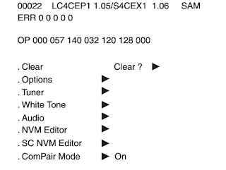
Displaying the adjustment menu
Press [menu] button on the TV set to shift from adjustment mode to service mode and vice versa.
Service mode keys
     Select adjustment item by pressing the [channel+] or [channel-} button on the remote        control handset.
     Adjust data value by pressing the [Volume+] or [Volume-] button on the remote control handset.
Cancellation of service mode
To return to normal TV mode, press Power] / [Standby] button to turn off TV once

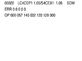
Service mode adjustments

Following adjustments items will appear on the screen.

Item         Name of adjustment                                             Reference data
R CUT     R CUTOFF B/W                                                              40H
G CUT    G CUTOFF                                                                      40H
B CUT     B CUTOFF                                                                      40H
GDRV     G DRIVE                                                                         40H
BDRV     BLUE DRIVE                                                                   40H
CNTX      SUB-CONTRAST MAX(4:3 MODE)                                  7FH
BRTC      SUB BRIGHT CEN                                                          7FH
COLC      SUB COLOR CEN NTSC                                                  39H
TNTC       SUB TINT GEN                                                                40H
COLP      SUB COLOUR CEN PAL                                                  39H
COLS      SUB COLOUTR CEN SECAM                                          27H
SCOL      SUB COLOUR                                                                 13H
SCNT      SUB CONTRAST                                                              2H
VOLS      VOL SCART                                                                     75H
FVOL      FM VOL PRE SCALE                                                       15H
NVOL      NICAM VOL PRE SCALE                                                 3AH
NICL        NICAM THRESHOLD LEVEL                                           03H
NICH       NICAM THRESHOLD LEVEL                                            0AH
IDL          IGR THRESHOLD LEVEL                                                 04H
IDH         IGR THRESHOLD LEVEL                                                 0EH
EVOL      EXT PRE VOLUME                                                            01H
EMX        NICAM ON LEVEL                                                             FCH
EMN        NICAM ON LEVEL                                                             64H
FMA        FM ATTENNUATOR LEVEL                                              00H
STS         STEREO SEPERATION                                                     00H
HPOS     50HZ HORIZONTAL POSITION                                        FEH
VPOS      V-POSITION                                                                      0DH
HIT          HEIGHT                                                                             3EH
VLIN        V-LENEARITY                                                                   17H
VSC        V-S CORRECTION                                                              18H
VPS         V-SHIFT                                                                             0CH
VCP         V-COMPENSATION                                                            07H
WID         PICTURE WIDTH                                                                18H
PARA      E-W PARABOLA                                                                  22H
CNR        E-W CORNER                                                                      04H
TRAP      TRAPEZIUM                                                                         0FH
HCP        H-COMPENSATION                                                            01H
VFC         V-F CORRECTION                                                              0FH
BELL       SECAM BELL FILTER                                                        80H
SRY        SECAN R-Y                                                                          08H
SBY        SECAM B-Y                                                                          08H

INITILIZATION OF MEMORY DATA OF QA02
 After replacing IC the following initialization is required.
  Enter the service mode then select any register item.
  Press and hold the [call] button on the remote then press the [channel+] button on      the TV.  The initialization of IC has been completed.
  Check the picture carefully.  If necessary, adjust any adjustment item as explained below.
Perform auto search memory as explained in the owner’s manual.
CAUTION:- Never attempt to initialize the data unless memory IC has been replaced.
Test signal selection
      In the service mode, pressing of [AV] / [Video] button shows the test patterns on screen.  Every pressing of [AV] / [Video] button cycle through 14 NTSC test patterns and 14 PAL test patterns.

Some of the test patterns are:

        Red single colour, green single colour, blue single colour

Black single colour, white single colour
White balance adjustment pattern
Black cross- bar, white crossbar
Black crosshatch, white cross hatch
Black cross dot, white cross dot, h signal etc.
 White balance adjustment
   Cutoff adjustment [RCUT] [GVUT] [BCUT]
   Drive adjustment [GDRV] [BDRV]
  • Set contrast to 40, and brightness to +20 by picture control.
  • Set the TV in service mode, and get the inside W/B adjustment signal with [AV/Video] button.
  • Select R CUT, G CUT, AND B CUT with [Channel+/-] buttons, to set individual values to 32, and to set GDRV and BDRV to 20 with [Volume+/-] buttons.
  • Press [-/--] button on the remote control and rotate screen VR to get one slight horizontal line on screen.
  •   Every pressing of [-/--] button provides horizontal line picture and o\normal picture    alternately.
  • Press [-/--] button to release horizontal line picture, and select the two other colours which did not light in the above step with  [CHANNEL+/-].  Then tap [Volume+/-] buttons so that three colors slightly light in the same level..
  • To correct white balance in light area, select GDRV and BDRV with [CHANNEL+/-] buttons to adjust.
  • To correct white balance in dark area, perform fine adjustment to RCUT, GCUT and BCUT.

Self-diagnostic function.
  •      Press [9] button on the remote control during display of adjustment menu.
  • The diagnosis will begin to check if interfaces among ICs are executed properly.

During diagnosis the following displays are shown.
                                         -----------------------------------------------------------------------
                                         <Self check>

                                         2390****

                                         power                                                             00
                                         bus line                                                          OK
                                         bus cont                                                        OK
                                         block                                                              UV V1 V2
                                                                                                                     QV01
                                         ------------------------------------------------------------------------
  Values 1-5 are explained below

Part number of micro control

  • Operation number of protecting circuit-“00” is normal.     When indication is other than “00”, over-current apts to flow, and circuit parts may possibly    damaged.

BUS LINE CHECK OK  NORMAL
“SDA 1- GND” means that SDA line is shorted to ground
“SCL - GND” means that SCL line is shorted to ground.
“SCL 1-SDA 1” means that SDA line is shorted to SCL line
      bus cont “OK” is normal
When indication shows “Q000 NG”, the device with the number may possibly damage.
        Block
UV-TV reception mode
V1-VIDEO 1 INPUT MODE (AV1)
V2-VIDEO2 input mode (AV 2)
Indicated colour of mode now selected: Green and Red.
Indicated colour of other modes: White.
Green ; Normal
Red : the microcomputer operates to provide judgment of no video signal.  The red color is still indicated through the signal is input 
QV01: In case of indication green-normal. In case of indication red with input signal -     
 failure may exist in output line including QV01.
TOSHIBA – 2150 / 2876DD / 2988DG

Entering into service mode.
Press [Mute] button.  Press and hold [Mute] button and press [Menu] on local keyboard.
Service mode keys
Select [PR+/-], adjust [VOL+/-],Store; [Auto], test picture [AV] 
Cancellation of service standby.     

SONY DVP-S530D - TROUBLSEHOOTING HINTS [DIGITAL VIDEO PLAYER]

$
0
0

TROUBLESHOOTING
  When the model DVP-S530 DVD player is first plugged in and turned on, several things occur before “NO DISC” is displayed on the front panel. One operation is performed after the next until it reaches the end of the chain. A failure will prevent it from reaching the end and often a side trip is taken to protect the unit by shutting down. Finding out where in the chain the unit has stopped will help locate the failure. Below is general description of the start-up operations followed by problems and answers. Use the information below as a troubleshooting guide to remain on track throughout your testing.
                Operations
            Details found in:


Communications between Interface IC201 and Syscon IC202 on the serial bus.

Power Control section
Front panel blue Digital Dolby indicator lights.

Power Control section
Communications with other ICs on the parallel bus.

Parallel Data Communications section
SONY DVD appears on the fluorescent display.

Power Control section
Sensors are checked and the Transport is returned to the initial state (tray is closed, sled goes to home position).

Mechanism section
Sony DVD logo appears on the monitor (OSD)

See no logo problem listed below
Search for a disc is initiated using the focus search operation and other servos
Use the Test Mode section in the service manual to test the Laser,Focus,Spindle and Trackingservos. Then see the problem servo section

NO DISC is displayed in the fluorescent display
Serial Data Communications / Power Control section

GENERAL PROBLEMS
No Power ON
  • Unplug unit and press the POWER button to discharge the power supply.
  • Watch the front panel Dolby Digital indicator while plugging the unit into AC. If there is Interface IC201 to Syscon IC202 serial communications, the blue indicator will light momentarily.
  • Press the power ON button. If the unit does not remain ON, there is a loss of communication between Syscon IC202 and a slave IC or the servo IC701 failed to reset the mechanism.  Communications occur when Syscon IC202 Chip Selects several ICs, sends data and waits for an interrupt reply from each. Use the scope to look for a low interrupt reply pulse at these ICs highlighted (in bold) while repeatedly pressing the power button to reinitiate the sequence:
  • After the brief communications above, the servo IC701 must initialize the mechanism by closing the tray and moving the sled to home position. When completed, IC701 replies to Syscon IC202. If no reply is received within approximately 2 seconds of powering ON, IC202 instructs Interface IC201 to power down (set OFF).

   Interrupt pulse From
     Through IC601

              To
ARP2 IC303/pin 86 (Wait)
In pin 108 (arpwt)
Out pin 157 (wait)


A/V Decoder IC401/pin 198(wait)
In pin 72 (avdwt)
Out pin 157 (wait)

IC202/pin 19 (Ready)
A/V Decoder IC401/pin 196 (interrupt)

Direct
IC202/pin 95 (interrupt)
Interface IC201/pin 78
(CN006/pin 2)
In pin 22 (interrupt)
Out pin 155 (Interrupt 3)

IC202/pin 88 (interrupt)
ARP2 IC303/pin 83 (Interrupt)
In pin 107 (interrupt)
Out pin 156 (Interrupt 1)

IC202/pin 94 (interrupt)
Servo IC701/pin 128 (Interrupt)
In pin 107 (interrupt)
Out pin 156 (Interrupt 1)


EEProm IC201/pin 1
(busy)
In pin 25 Out pin 155 (Interrupt 3)

IC202/pin 88 (interrupt)
DSP IC501/pin 55
(Interrupt 0)
IN pin 29 Out pin 155 (Interrupt 3)


DSP IC501/pin 56
(Interrupt 1)
IN pin 30 Out pin 155 (Interrupt 3)

NO DVD OSD LOGO
The DVD initial OSD power ON logo is stored in Flash ROM IC205. This information takes the following path to become video that outputs the AU212 board:
  • Flash ROM IC205 (storage)
  • Syscon IC202 (extraction and processing)
  • ARP2 IC303 (pass through)
  • A/V Decoder IC401 (sub-picture generation)
  • Video Buffers on the AU212 board
   In the test mode (Syscon Diagnosis/A/V Decoder test), the A/V Decoder can generate a main picture (color bar) or a sub picture CHG_COLCON”) from the flash ROM data. Unfortunately they take the same path as the logo, finally separating inside the A/V decoder IC401. Therefore if the logo, test bars or test sub picture does not appear, the problem may be the storage area in Flash ROM IC205. If none appear, the path from Flash ROM to A/V Decoder IC401 is broken.
NO DVD [CD-PB OK]
Use the test mode to perform the DVD auto adjustments using the DVD test disc.
Use the test mode to examine the OSD emergency code entries for failures. The emergency code list description is in the DVP-S330/S530/S550/S705 service manual on page 6-10E. The front panel customer code errors are preceded by a C and listed on the manual.
Use the test mode to manually play the DVD disc by activating servos 1-6 individually.
The minimum (marginal) eye pattern amplitude is 0.8Vp-p @ CN012/pin 1. Clean lens or replace laser. Follow eye pattern into ARP2 IC303/pin 17 (1.4Vp-p) which should produce less than 0.5Vdc at IC303/pin 57 if the PLL clock is able to lock to the data. Insufficient IC303/pin 17 input level will prevent a lock and so will a defective IC303.

   This DVD player uses the laser and focus servos to identify the DVD.  One may not be working. From the test mode, manually turn on the laser and focus search servos (Drive Manual Operation/Servo Control) for observation. · Laser test – using a light meter measure the laser light (never look directly at the laser) and measure voltage across R006 (laser current). 1Vdc or more across R006 means the laser is at the end of life.  The light measurement is quick but not a definitive test. The current measurement is better.
Focus search test– Scope FE (test connector CN012/pin 3) for 1.5Vpp minimum sine wave used for disc layer ID. Scope MIRROR output at CN002/pin 16 for 3Vp-p pulses during the search. The Mirror signal is an amplified the PI signal. Both come from RF Amplifier IC001.
NO DVD DL PB [OTHER DISC PB OK]
  • Perform the test mode’s “Drive Auto Adjustments” using a Single, and then a Dual layer disc, to reload data into the EEProm IC201.
  • Check the operation of the tilt circuit in the test mode by seeing if the tilt incline gear moves manually (Test mode/Drive Manual Operation/
  • Manual Adj/Tilt Position).
  • A single layer DVD Eye pattern’s minimum level is 0.8Vp-p at the MB-85 board test connector CN012/pin 1. The laser level is affected by dirt/oil in the lens and the tilt circuit. A new laser will output approximately 1.2Vp-p.
NO DISC PB
  • Use the test mode to perform the CD auto adjustments.
  • Use the test mode to examine the emergency code entry for failures.
  • Use the test mode to manually PB the CD disc by activating servos 1-6 individually to see if one is faulty.  4. The minimum (marginal) eye pattern amplitude is .8Vp-p @ CN012/pin 1. Clean lens or replace laser. Follow eye pattern into ARP2 IC303/pin 19 (1.4Vp-p) which should produce less than 0.6Vdc at IC303/pin 57 if PLL clock is locked (3V= no lock, 0V = defective IC or external short).

PANASONIC DVD RV-30BR - HOW TO DISASSEMBLE DECK MECHANISM - [Deck disassemble Procedure]

$
0
0

DISASSEMBLING THE CLAMP BASE UNIT
Remove the two screws
Clamper weight, Clamper yoke, Magnet & Clamper
Release the 3 tabs on the Clamper
DISASSEMBLE THE TRANSVERSE UNIT
Disconnect the 2 flexible cables.
THE STEPPING MOTOR UNIT
Disconnect the flexible cable and remove the two screws.
PICKUP UNIT
Remove the screw.
Release the tab.
Remove the guide shaft
NUT UNIT DISASSEMBLE
The nut unit is not the part of optical pick-up.  Before replacing the optical pick-up remove the nut unit for use with the new optical pick-up.  
After installation use screw lock to lock the screw in position.
When re-assembling, use the screw lock to lock the screw in position after attaching it.
ASSEMBLING THE OPTICAL PICK-UP
Install the optical pick-up. [Take care not to attach the tilt spring and guide shaft in wrong order.
Insert the pick-up FPC into connector FP5201 on the module PCB.
Remove the solder from the pick-up FPC's solder-short circuit.
Adjust the optical pick-up tilt after removing the solder.
THE SPINDLE MOTOR DISASSEMBLE PROCEDURE
Remove three screws.  Be sure to adjust the optical pick-up tilt after replacing the spindle motor unit.

Viewing all 2033 articles
Browse latest View live


<script src="https://jsc.adskeeper.com/r/s/rssing.com.1596347.js" async> </script>