Quantcast
Channel: Electro help
Viewing all 2033 articles
Browse latest View live

LG 32FS4RNP - SCHEMATIC - POWER SUPPLY (STR F6458) - VIDEO OUTPUT

$
0
0


SMPS SCHEMATIC
VIDEO OUT [CRT BASE CARD]
CLICK ON THE PICTURES TO ZOOM IN


SONY KDL 40U4000 - FLAT PANEL TV - POWER SUPPLY [SMPS] SCHEMATIC [CIRCUIT DIAGRAM]

$
0
0

SCHEMATICS
CLICK ON THE SCHEMATICS TO MAGNIFY

DISASSEMBLE [OPEN] - SONY KDL40U4000 - LCD TV - LED BLINKING CODES

$
0
0
LED BLINKING CODES
The identification of errors within the EG1L-L chassis is triggered in one of two ways: - 1: Busy or 2: Device failure to respond to IIC. In the event of one of these situations arising the software will first try to release the bus if busy (Failure to do so will report with a continuous flashing LED) and then communicate with each device in turn to establish if a device is faulty. If a device is found to be faulty the relevant device number will be displayed through the LED (Series of flashes which must be counted).
LED ERROR CODES
REAR COVER REMOVAL
STAND REMOVAL
POWER BOARD REMOVAL
CLICK ON THE PICTURES TO ZOOM IN

HP Pavilion Notebook PC - HOW TO REPLACE KEYBOARD [User Replaceable]

$
0
0

KEYBOARD REPLACEMENT (User Replacable)
1. Unplug the AC adapter, if present, and then remove the battery.

2. Remove the keyboard cover.

3. Remove the four M2.5×4.0mm screws that secure the keyboard to the top case.

4. Lift up on the keyboard at the switchboard PCA end, and then pull it toward the display assembly to release the tabs from the top case.

5. Turn the keyboard over, and then disconnect the motherboard cable.

6. Remove the keyboard. [Do not excessively bend or fold the keyboard cable. Excessive flexing can damage the keyboard cable connectors.]
Lay the keyboard face down on the top case, forward of its normal position, and then reconnect the keyboard cable.

Slide the metal tabs on the bottom of the keyboard into their slots in the top case, and then lower the keyboard into place.
Removing the Keyboard Cover
1. Unplug the AC adapter, if present, and then remove the battery.
2.Remove the two M2.5×4.0mm hinge cover screws that secure the keyboard cover to the rear of the notebook.
3. Carefully insert a flat-blade screwdriver blade under the keyboard cover near the right end, and then near the center, then near the left end, and then gently lift up the center of the cover. Gently pry up the hinge covers if needed, being careful not to damage the plastics or wireless antenna underneath.
4. If necessary, while holding the center of the cover, carefully insert the flat-blade screwdriver under the right side of the display assembly hinge, gently pry up, and then lift the cover out. This procedure might need to be repeated on the left side of display assembly hinge to completely remove the cover.
Be careful not to damage the antenna PCA that is connected to the left and right display assembly hinges. Damaging either antenna PCA can degrade notebook performance.

DELL S1709WC - 17" LCD Color Monitor - POWER 7 INVERTER - SCHEMATIC [CIRCUIT DIAGRAM]

$
0
0
SMPS [POWER]
INVERTER [BACK-LIGHT]
CLICK ON THE SCHEMATICS TO ZOOM IN

HOW TO DISASSEMBLE [OPEN] - DELL-S1709WC - LCD MONITOR

$
0
0
TO REMOVE STAND
Remove the two screws and remove the stand.
Pull out the hinge cover follow the arrowhead direction and remove it, then remove the hinge.
Click on the pictures to Zoom In
Remove the two screws and remove the base.
Pry the monitor up then find out the hooks’ position, use the tool (like the picture or other card) to insert into the gap of bezel and rear cover, then turn over the monitor and take off the rear cover.
Remove the one screw and remove the keyboard.
Disconnected the keyboard connector.
Remove the screw and remove the small cover shield.
Remove the screws and then remove the shield.
Remove the screws remarked in red and disconnect connector remarked in green.
Remove the screws and remove the main frame.
Note: Make LVDS connector’s metal side down.

KEYBOARD REPLACEMENT- HP Compaq Notebook nc4000 Series (User Repairable)

$
0
0

Prepare to replace the Keyboard:
Turn off the notebook.
Disconnect the AC adapter and all external devices.
Remove the battery pack by following these steps:
a. Turn the notebook bottom side up with the front facing forward.
b. Slide and hold the battery release latch [1] to the left. The rear edge of the battery pack releases from the notebook.
c. Lift the rear edge of the battery pack up and swing it forward [2].
d. Remove the battery pack.
LED switch cover removal
Close the notebook and turn it bottom side up with the rear panel facing forward.
Remove the two T8M2.0×8.0 screws that secure the LED switch cover to the notebook.
Turn the notebook topside up with the front facing forward.
Open the notebook as far as it will open.
Press down on the (esc) key 1 to reveal the notch 2 in the left side of the LED switch cover.

Insert a flat-bladed tool into the notch and lift the left side of the LED switch cover 3.

After the left side of the LED switch cover has disengaged from the notebook, swing the LED switch cover up and to the right.

Remove the LED switch cover.
Close the notebook and turn it bottom side up with the rear panel facing forward.
Remove the T8M2.0×8.0 screw that secures the keyboard to the notebook.

Turn the notebook topside up with the front facing forward.

Open the notebook as far as it will open.
Lift the rear edge of the keyboard 1.

Slide the keyboard toward the display 2 until the notches on the front edge of the keyboard clear the top cover.

Swing the front edge of the keyboard up and back 3 until it rests on the display.
Release the zero insertion force (ZIF) connector 1 to which the pointing stick cable is attached and disconnect the pointing stick cable 2 from the system board.
Release the ZIF connector 3 to which the keyboard cable is attached and disconnect the keyboard cable 4 from the system board.
Remove the keyboard.

Reverse the above procedure to install the keyboard.

LG RAD 225B - RAS 225 [HTS] - POWER SUPPLY & POWER AMPLIFIER - SCHEMATIC [CIRCUIT DIAGRAM]

$
0
0
POWER AMP
SMPS
CLICK ON THE SCHEMATICS TO MAGNIFY 


PHILIPS 42PFL7007 - INVERTER AND POWER SUPPLY [SMPS] - SCHEMATIC

$
0
0

SCHEMATICS (POWER_SMPS)
BACK-LIGHT INVERTER [CLICK ON THE SCHEMATICS TO ZOOM IN]

32PFL4507 - PHILIPS LCD TV - POWER SUPPLY [SMPS] - SCHEMATIC (Circuit Diagram)

$
0
0

SMPS
Fixed voltage (or Auto voltage selectable) power supply circuit is used in this unit.  If Main Fuse (F601) is blown , check to see that all components in the power supply circuit are not defective before you connect the AC plug to the AC power supply.  Otherwise it may cause some components in the power supply circuit to fail.
For continued protection against risk of fire, replace only with same type 4A, 125V fuse.
APPLICABLE TO:
32PFL4507/F7 PHILIPS (Serial No.: DS1)
32PFL4507/F8 PHILIPS (Serial No.: XA1)
32PFL4507/F8 PHILIPS (Serial No.: DS1)
TYPE B:  32PFL4907/F7
PCB-TOP
PCB-BOTTOM {CLICK ON THE PICTURES TO MAGNIFY}

PHILIPS TV - L04A CHASSIS - POWER SUPPLY [SMPS] & SCAN OUT - SCHEMATIC [CIRCUIT DIAGRAM]

$
0
0
SMPS
LINE_FRAME DEFLECTION
CLICK ON THE SCHEMATICS TO ZOOM IN

SMPS [Power Supply] - SCHEMATIC - PHILIPS 26PFL3405 – 22PFL3405 – 19PFL3405

$
0
0

26" POWER BOARD.
19"& 22" POWER BOARD
CLICK ON THE SCHEMATICS TO MAGNIFY

HOW TO DISASSEMBLE - SAMSUNG UN37C5000QF LCD TV [LED LCD TV]

$
0
0

Disconnect the LCD TV from the power source before disassembly.

Follow these directions carefully; never use metal instruments to pry apart the cabinet.
To remove the stand.

Place monitor face down on cushioned table. Remove 5screws from the stand.  Remove stand.
Remove the 19 screws of rear-cover.  Remove the screws of rear-cover.
Lift up the rear-cover.
Remove the speaker and Woofer.
Lift up the stand link.  Remove the 4 screws of bracket stand link.
Remove the 5 screws of main board and 5 screws of IP board.
Lift up the panel.
CLICK ON THE PICTURES TO ZOOM IN


UN40C5000QF - UN46C5000QF – SAMSUNG LED TV - TROUBLESHOOTING (NO POWER)

$
0
0

TROUBLESHOOTING
Check to see if any cables are damaged or burnt.

Check to see if there is a disconnected or loose cable connection.

Check to see if the cables are connected according to the connection diagram.

Check the power input to the Main Board.
THERE ARE TWO TYPES OF CIRCUIT BOARDS TO THESE TVs
TYPE-A [NO POWER]
BOARDS LOCATIONS
TYPE-B [NO POWER]
CLICK ON THE PICTURES TO ZOOM IN

HYUNDAI HPTV2912S - 29 INCH CRT TV - POWER SUPPLY SCHEMATIC (Circuit Diagram)

$
0
0


SMPS SCHEMATIC [Click on the Schematic to Zoom In]


PHILIPS - 42PFL3403 – 42PFL5403 – 42PFL6403 - POWER [SMPS] - SCHEMATIC (CIRCUIT DIAGRAM)

$
0
0

POWER SUPPLY [SMPS]
CLICK ON THE SCHEMATICS TO MAGNIFY 

SMPS POWER SUPPLY - TDA4605_TDA8138 IC BASED - FORMENTE-F19

$
0
0

SMPS SCHEMATIC
CLICK ON THE SCHEMATIC TO ZOOM IN

SAMSUNG UN40C5000QF - UN46C5000QF - SERVICE MODE - USB DOWNLOAD

$
0
0

USB DOWNLOAD PROCEDURE
Software Upgrade upgrades can be performed via broadcasting signal or by downloading the new firmware from samsung.com to a USB memory device.
Current Version is the software already installed in the TV.
Note  Software is represented as ‘Year/Month/Day_Version’.
Installing the latest version is recommended.
By USB : Insert a USB drive containing the firmware upgrade file downloaded from samsung.com into the TV. Please be careful not to disconnect the power or remove the USB drive until upgrades is complete. The TV will turn off and on automatically after completing the firmware upgrade. When software is upgraded, video and audio settings you have made will return to their default settings. We recommend you to write down your settings so that you can easily reset them after the upgrade.
By Online: Upgrades the software using the Internet.
Note first, configure your network.
For detailed procedures on using the Network Setup, refer to the ‘Setting the Network’ instructions. [Refer User Manual for details]
Note If the internet connection doesn't operate properly, the connection may be broken.
Please retry downloading. If the problem still happens, download by USB and upgrade.
Alternative Software (Backup): If there is an issue with the new firmware and it is affecting operation, you can change the software to the previous version.
Note If software was changed, existing software is displayed.
Entering Factory Mode
To enter ‘Service Mode’ Press the remote -control keys in this sequence:
If you do not have Factory remote - control
Power Off_ MUTE_ 1_ 8_ 2_ Power On
How to Access Service Mode
1] Turn the power off and set to stand-by mode.
2] Press the remote buttons in this order; MUTE-1-8-2-POWER ON to turn the set on.
The set turns on and enters service mode. This may take approximately 20 seconds.
Press the Power button to exit and store data in memory.
If you fail to enter service mode, repeat steps 1 and 2 above.
INITIAL SERVICE MODE DISPLAY
CLICK ON THE PICTURES TO MAGNIFY
How to enter the hidden factory mode.
a. into the factory mode
b. scroll down and highlight advanced
c. key input : 0 + 0 + 0 + 0
** hidden menu : Picture
But you can't modify the menu (2010 models)
Buttons operations within Service Mode
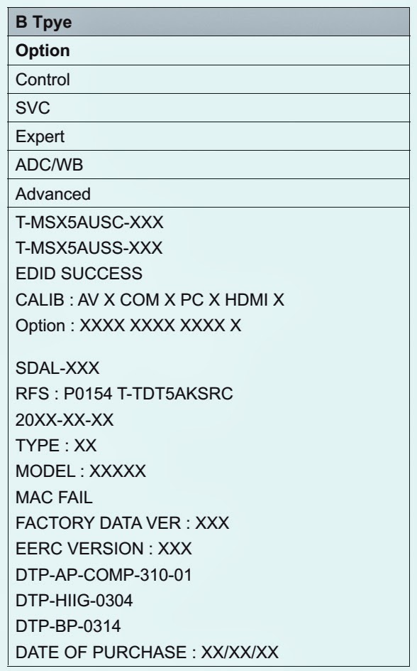
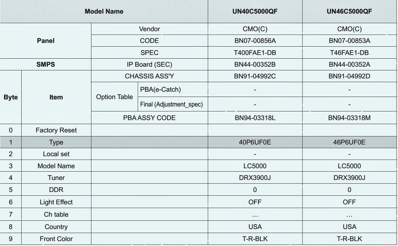
Detail Factory Option [UN40C5000QF - UN46C5000QF]
If you replace the main board with new one, please change the factory option as well.
The options you must change are “Type”.

PHILCO PH46-LED LCD TV - LED LCD TV - MAIN POWER [SMPS] SCHEMATIC (Circuit Diagram)

$
0
0

SMPS SCHEMATIC

CLICK ON THE SCHEMATIC TO ZOOM IN

PH55 - PHILCO LED TV - SMPS (Power Supply) - SCHEMATIC (Circuit Diagram)

$
0
0

SMPS CIRCUIT DIAGRAM
CLICK ON THE SCHEMATIC TO MAGNIFY

Viewing all 2033 articles
Browse latest View live


Latest Images