Quantcast
Channel: Electro help
Viewing all 2033 articles
Browse latest View live

HOW TO DOWNLOAD EDID - DDC - LG42LG70 - LCD TV

$
0
0

EDID (The Extended Display Identification Data) / DDC (Display Data Channel) download 
VESA specification. Function to implement the "Plug and Play" for automatically re configuring the user environment to directly use by exchanging the information with no direct command to the PC or the monitor from the user.
Device to use
PC (S/W included: EDID Data Write & Read)
EDID DOWNLOAD JIG
HDMI Cable, D-sub Cable.
Device configuration diagram for HDMI EDID Data input
1] Configure the download environment as shown at the adjustment wiring diagram and turn on the PC.
2] Execute the DDC program. (EDID Data Write & Read)
3] Go to Model -> Open, and select the EDID data of the desired model.
4] Check the item to download from the <Test> item
4-1] HDMI & RGB: Check Digital & Analog
4-2] (Only) HDMI: Check Digital only
5] Press ESC(Cancel Mode) -> F8(Auto Mode). (Set Auto Detecting)
6] Connect the desired signal cable to the set.
7] Make sure that the popup "Proceed to write?" is displayed.
8] Press the Enter key or the space key to download.
9] After downloading, check the OK message and disconnect the connected cable.
Note: Because downloading can be down at the power on mode only, if it is not set, press the Power ON key of the remote controller to proceed.
Click on the Tables to Zoom In


LG 42LH3000 - LG47LH3000 - LG37LH3000 - LCD TV - TROUBLESHOOTING

$
0
0

TROUBLESHOOTING
Video Error
First of all, check whether all of cables between board is inserted properly or not. (Main B/D Power B/D, LVDS Cable,Speaker Cable,IR B/D Cable)
NO VIDEO_NORMAL AUDIO
NO VIDEO - NO AUDIO
PICTURE BROKEN / FREEZING
COLOR ERROR
Vertical / Horizontal bar, residual image, light spot, external device color error.
POWER ERROR
Off when on, off while viewing, power auto on/off.
CLICK ON THE TABLES TO MAGNIFY

AKAI SMPS SCHEMATIC - AKAI 21CTU91BC - AKAI 21CTU93BC - AKAI 21CTU94BC - Service Mode

$
0
0
SMPS SCHEMATIC
CLICK ON THE SCHEMATIC TO ZOOM IN
Memory IC Replacement & Factory Mode Entry Procedure
  This TV uses memory IC. In the memory IC are memorized data for correctly operating the video and deflection circuits. When replacing memory IC, be sure to use IC written with the initial value of data.
PROCEDURE FOR REPLACING MEMORY IC
(1) Power off:  Switch the power off and unplug the power cord from AC outlet.
(2) Replace IC:  Be sure to use memory IC written with the initial data values.
(3) Power On:  Plug the power cord into the AC outlet and switch the power On.
(4)  Check and set SYSTEM default value:
Note: enter a factory mode method
1)  Factory remote control: Press the factory remote control up [PRESET], press again[TEST]key, appear on the television screen 'M'.
2)  Customer remote control
3)  Press  [menu]  key,  appear  the  picture menu, press few character keys 6483, the screen appears M.
4)  Press [standby] key, withdraw factory mode.
5)  The “TEST” will be displayed on the screen.
6)  Check the setting value of the SYSTEM default value of Table below. If the value is different, select items by [CH+]/[CH-] keys and set value by VOL+]/[VOL-] keys.
7) Press “STANDBY” key again and return to the normal screen.

25CT23FSR - AKAI TV - SCHEMATIC - STR-F6454R & TDA9384_System-Chroma Jungle IC

$
0
0
SMPS CIRCUIT
CLICK ON THE SCHEMATICS TO MAGNIFY
FULL

HOW TO ENTER SERVICE MODE - AKAI 25CT23FSR - DEFAULT DATA TABLE

$
0
0
SERVICE MODE
Set the volume to "0" by the remote control. 
Then press and hold the MUTE button on the remote control and MENU button on the TV at the same time for over 2 seconds. 
In the S mode, press the POWER button to quit the S mode.
( S is red and other items are yellow.)
Use the ▲/▼ buttons on the remote control to highlight an adjustment and the  ◄/► buttons to adjust it.
The POS +/-,▲▼,1~6, RECALL, VOL+/-, MUTE and POWER buttons on the remote control function in the S mode, but 100+, 7, 8, 9 and 0 buttons not.
BUS DATA

HOW TO DISASSEMBLE - SAMSUNG UE & UD SERIES - LED LCD TVs

$
0
0

DISASSEMBLE PROCEDURE [SAMSUNG UD5500_UD5700 (32", 37", 40", 46") / UD4000 (32")]
Place the TV face down on cushioned table.  Remove 4 screws from the Stand.(machine type)
Remove Stand.
Remove the screws of Rear-Cover.
32" : Remove the 11 screws. (machine type : 2 EA)
37" : Remove the 12 screws. (machine type : 3 EA)
40" : Remove the 16 screws. (machine type : 4 EA)
46" : Remove the 20 screws. (machine type : 5 EA)
Lift up the Rear-Cover.
Remove the left and right speaker.
Remove the 6 screws of Main Board.  Remove the 5 screws of SMPS Board.
Remove the 6 screws of Bracket Stand Link & Guide. (Machine type : 4 EA)
Remove the Stand Link.
Lift up the Panel.
UD5000 (22", 27") / UD4000(19")
Place the TV face down on cushioned table.
Remove 4 screws from the Stand. 19", 22" : Remove 2 screws. 27" : Remove 3 screws.           
Remove Stand.
Remove the screws of Rear-Cover.
32" : Remove the 11 screws. (machine type : 2 EA)
37" : Remove the 12 screws. (machine type : 3 EA)
40" : Remove the 16 screws. (machine type : 4 EA)
46" : Remove the 20 screws. (machine type : 5 EA)
Lift up the Rear-Cover.
Remove the left and right speaker.
Remove the 4 screws of Main Board.
Remove the 3 screws of SMPS Board.
Remove the Stand Link.
Lift up the Panel.

PHILIPS POWER SUPPLY [SMPS] - SDI POWER SUPPLY _LJ44-00101C – FAULTS AND REPAIR – LED BLINKING CODES

$
0
0

ERROR CODES [LED BLINKS]
OVP: Over Voltage Protection
UVP: Under Voltage Protection
Protection Circuits
42” SD v5, 42” HD w1, 50” HD w1 Voltage Outputs
NO POWER
Check or change: *F8001(250V/8A) OPEN ** R8012, R8013 OPEN ***D8006 SHORT
Will continue by Next Post

PS-424 - PHILIPS POWER SUPPLY [SMPS] TROUBLESHOOTING - NO 5V2 - RELAY ON_OFF

$
0
0
NO 5.2V
Check or change:  F8001(250V/8A) OPEN.
Check or change: IC8003, Q8008,  D8018, ZD8225, D8016, ZD8100 , D8017, ZD8200
Check or change: Copper side: Q8002,  ZD8205, ZD8102
RELAY ON & OFF
Check or change:  U8003 DEAD.
Check or change: IC8012 DEAD.
Check or change: HIC8001 ALARM BOARD.
Check or change: IC8011 DEAD.


LG 42LH32FR - LCD TV - TROUBLESHOOTING TABLE

$
0
0
CLICK ON THE TABLES TO ZOOM IN
NO POWER
NO RASTER ON PC SIGNAL
NO RASTER ON AV/VIDEO

SAMSING SLIM CRT TV - CL14B501KJMXZD - POWER SUPPLY [SMPS] - STR-W6753F-SCHEMATIC [Circuit Diagram]

$
0
0

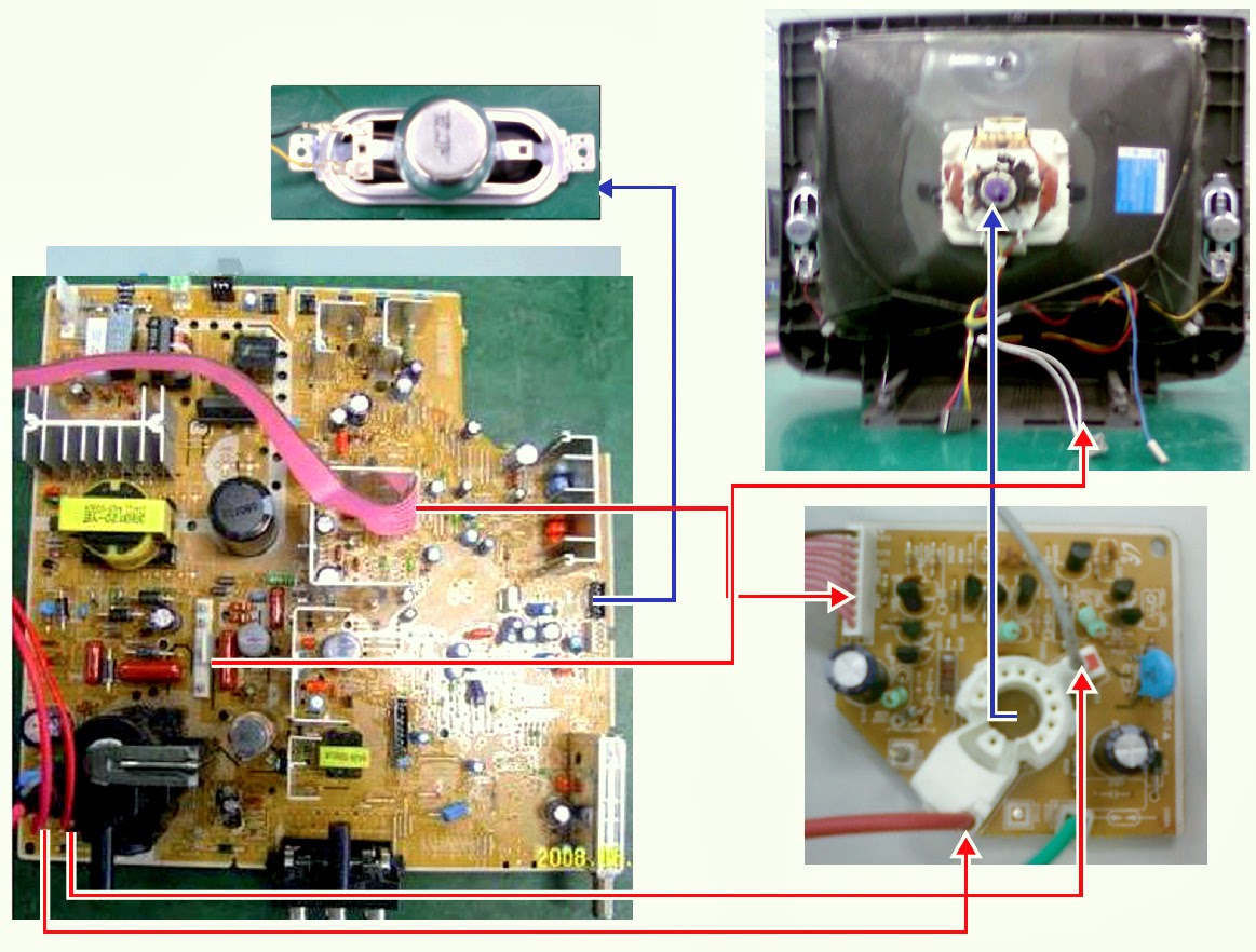
WIRING DIAGRAM
SMPS SCHEMATIC
CRT BASE CARD_SCHEMATIC
CLICK ON THE SCHEMATICS TO ZOOM IN

21 INCH SLIM TV - SAMSUNG - CL14B501KJMXZD - TROUBLESHOOTING - LED BLINKING

$
0
0
TROUBLESHOOTING
Troubleshooting by the  Checksum
Diagnosis of trouble by the checksum is neither  reliable nor convenient.
You can only use the checksum of the current direct-view TV to determine whether the software is corrupted or not.
The Checksum value is determined according to the version of the software loaded on the set.
Therefore, you can determine whether the software has been properly downloaded, if you know the correct checksum for that version of the software.
You can check the checksum according in the following order.
Factory Mode → Checksum → Enter → Output Checksum (e.g.0xab2b)
Checksum  Examples
T-SIXNSAM -1000.0 Checksum = XXXX
LED BLINKING
CLICK ON THE PICTURES TO MAGNIFY
NO POWER
NO SOUND
NO PICTURE

JBL - GT-BassPro12 – SCHEMATIC – Powered car subwoofer (Circuit Diagram)

$
0
0

POWER SUPPLY
CLICK ON THE PICTURES TO MAGNIFY
PRE
POWER AMP
PCB LAYOUT

DISASSEMBLE PROCEDURE-JBL GT-BassPro12 - Powered Car Sub-woofer

$
0
0

DISASSEMBLE PROCEDURE (Click on the pictures to Magnify)

JVC LT-37A80SU, LT-37A80ZU - Power Supply (SMPS) - Circuit Diagram - LCD INTEGRATED DIGITAL TELEVISION

$
0
0

SMPS SCHEMATIC [Applicable to LT-37A80SU, LT-37A80ZU - LT-37DA8BJ - LT-37DA8SU - LT-37DA8ZU - LCD INTEGRATED DIGITAL TELEVISION]
CLICK ON THE PICTURES TO ZOOM IN
SMPS_SPLIT

HOW TO ENTER SERVICE MODE - JVC LT-37DA8BJ - LT-37A80 LCD INTEGRATED DIGITAL TELEVISION

$
0
0

ADJUSTMENT PREPERATION
(1) This TV is adjusted by using REMOTE CONTROL UNIT.
(2)The adjustment using the REMOTE CONTROL UNIT is made on the basis of the initial setting values. The setting values, which adjust the screen to the optimum condition, can be different from the initial setting values.
(3) Make sure that connection is correctly made AC-to-AC power source.
(4) Turn on the power of the TV and measuring instruments for warming up for at least 30 minutes before starting adjustments.
(5) If the receive or input signal is not specified, use the most appropriate signal for adjustment.
(6) Never touch the parts (such as variable resistors, transformers and condensers).
SERVICE MODE [FACTORY MODE]
Applicable to JVC  LT-37A80SU, LT-37A80ZU, LT-37DA8BJ, LT-37DA8SU, LT-37DA8ZU 
Click on the pictures to Zoom In
NOTE: Before entering the SERVICE MODE, confirm that the setting of VCR/TV/DVD switch is at the "TV” side. If the switches have not been properly set, you cannot enter the SERVICE MODE.”
(1) Press the  [INFORMATION] key and  [MUTING] key simultaneously, to enter the SERVICE MODE.
(2) When the Main Menu is displayed, press [9].
(3) The screen shown is displayed, and the SYSTEM SETTING starts.
NOTE: When the SYSTEM SETTING is performed, all settings are reset to the factory setting. Perform the setting again.
SELECTION OF SETTING ITEM.
[FUNCTION UP/DN key. For scrolling up / down the setting items.
CHANGE OF SETTING VALUE (DATA): [FUNCTION LEFT/RIGHT key.  For scrolling up / down the setting values.
MEMORY OF SETTING VALUE (DATA)
Changed setting value is memorized by pressing [OK] key.
SERVICE SELECT KEY LOCATION
When a number key other than the [1] key is pressed in the SERVICE MODE SCREEN, the other relevant screen may be displayed.
This is not used in the adjustment procedure.
Press the [MENU] key to return to the SERVICE MODE SCREEN.
SETTING THE ITEM NAME
Setting item name are displayed. The setting item numbers to be displayed are listed below.
INITIAL SETTING VALUES IN THE SERVICE MODE
Perform fine-tuning based on the "initial values" using the remote control when in the Service mode.   The "initial values" serve only as an indication rough standard and therefore the values with which optimal display can be achieved may be different from the default values.
Never change the values of the items( == ) that are not described in ADJUSTMENT PROCEDURE or in the below table as they are fixed values.
MEMORY IC REPLACEMENT PROCEDURE
1. Power off.  Switch off the power and disconnect the power plug from the AC outlet.
2. Replace the memory IC.  Be sure to use the memory IC written with the initial setting values.
3. Power on. Connect the power plug to the AC outlet and switch on the power.
4. Receiving channel setting.  Refer to the OPERATING INSTRUCTIONS and set the receive channels (Channels Preset) as described.
5. User setting.  Check the user setting items according to the given in page later. Where these do not agree, refer to the OPERATING INSTRUCTIONS and set the items as described.
6. SERVICE MODE setting.  Verify what to set in the SERVICE MODE, and set whatever is necessary 2). Refer to the SERVICE ADJUSTMENT for setting.


AKIRA MICROWAVE OVEN - MW700M17L - TROUBLESHOOTING - SCHEMATIC

$
0
0

WIRING
TROUBLESHOOTING
THERMAL PROTECTOR REMOVAL
1.  Unplug the power cord, remove the outer cabinet and discharge the capacitor.
2.  Disconnect the connectors from the thermal protector terminals.
3.  Remove the thermal protector mounting screw.
4.  Remove the thermal protector.
5.  Reverse procedure to replace.
MAGNETRON ASSEMBLY REMOVAL
1.  Unplug the power cord, remove the cabinet and discharge the capacitor.
2.  Remove the front and rear air guides and thermal protector from the magnetron.
3.  Remove the four-magnetron mounting screws from the side of oven cavity.
4.  Disconnect wire leads from magnetron and replace on new magnetron, wire for wire.
5.  Reverse the above procedure to reinstall new magnetron and reassemble.
NOTE: DO NOT LOSE SCREWS, THEY ARE M4 METRIC.
IMPORTANT: DO NOT OPERATE THE OVEN WITH THE MAGNETRON DISASSEMBLED FROM THE WAVE-GUIDE
Thermal Protector

HBUSTER HBD-7310 - CAR STEREO - SCHEMATIC (Circuit Diagram)

$
0
0
SCHEMATIC DIAGRAM[CLICK ON THE SCHEMATICS TO ZOOM IN]

SANYO DC-DA2000 - SCHEMATIC (Circuit Diagram) - MICRO COMPONENT SYSTEM

$
0
0

SCHEMATIC - FRONT END(CLICK ON THE PICTURES TO ZOOM IN)
SCHEMATIC - CD
PWB - FRONT END & CD
SCHEMATIC - TUNER
SCHEMATIC - AMPLIFIER
PWB - AMP & TUNER

SAMSUNG MX-C730 - MX-C630 - HOW TO SET BUYER REGION CODE

$
0
0

REGION CODE SETTINGS & REGION CODES
[1] Press the “AUX” button on the remote control.
[2] Press the “ANGLE” button on the remote control during 4~5 seconds.
[3] After step (2), you can see “TEST − −” on the VFD. Insert number “33”, “33” to select Region Code.
[4]  After step (3), you can see “− −” on the VFD.  Insert the Region Code corresponding model with “0 ~ 9” buttons on the remote control.
[5] Turn the Power off.
REGION CODES

LG RAT376 - SMPS (Power Supply) - SCHEMATIC (Circuit Diagram) - Mini Hi-Fi System

$
0
0

SMPS SCHEMATIC
CLICK ON THE SCHEMATIC TO ZOOM IN

Viewing all 2033 articles
Browse latest View live


<script src="https://jsc.adskeeper.com/r/s/rssing.com.1596347.js" async> </script>