↧
BN 96 - SAMSUNG POWER SUPPLY SCHEMATIC (Circuit Diagram)
↧
XOCECO 32HE42 POWER SUPPLY REGULATOR [SMPS] – SCHEMATIC (China)
↧
↧
HOOVER VHD-812 WASHING MACHINE/WASHER-DRYER/ DISASSEMBLE/PARTS
↧
INFINITY INTERMEZZO 4.1t POWERED LOUDSPEAKER – Connections & Controls.
CLICK ON THE PICTURES TO MAGNIFY
CONNECTIONSFor Methods 2, 3a, 3b and 4, make sure all bass management features are properly set. The Audio channels should all be set to “Small” or “High Pass” and the subwoofer set to “On.”
2-Channel receiver or integrated amplifier that has no subwoofer output or Pre-Out/Main-In connectors [1]
2-Channel receiver or integrated amplifier with preamp output and input connectors [2]
2-Channel system with separate preamplifier and power amplifier [2].
Dolby Pro Logic® with THX, Dolby Digital, or DTS ® receiver with a filtered subwoofer (or LFE) output connector [3a]
Dolby® Digital or DTS processor with separate power amplifiers or multi channel amplifier 3b Non-THX® -certified Dolby Pro Logic receiver with full-range subwoofer outputs [4].Final Positioning
After correctly connecting the Intermezzo 4.1t and verifying that both the subwoofer and main section portions are playing, it is time to optimize the system for your particular listening room. Earlier, you placed the loudspeakers in their general location. Finding the exact location for optimum performance sometimes only involves moving the speakers up to a few inches in any direction. We urge you, therefore, to experiment with placement until your speakers deliver their full potential. When the speakers are moved inward (toward each other) there is generally better focus of instruments and vocalists; however, moving the speakers too close together can reduce the spaciousness of the stage effect and you may need to experiment with the trade-off between focus and imaging. If your listening room is larger than average and your listening position is relatively far from the speakers, wider placement of the speakers may be required.
ADJUST BIAS PROCEDURE
(Mandatory when any output MOSFET transistors Q305, 310, 320, 321, 306, 307, 311, 312 are replaced)
1. Amplifier should be unplugged and OFF.
2. Remove Amp assembly from cabinet; remove rear plastic guard, and detach entire assembly from black plastic cup containing the controls. All wires exiting the assembly can remain connected unless they will prevent you from removing the amplifier or accessing potentiometers on the Linear board PCB in the following steps.
3. Identify the Linear board assembly (PCB with the output transistors).
4. Adjust RP301 and RP302 fully counterclockwise. See diagram below.
5. Apply 120 VAC power to unit; turn power switch ON.
6. Verify that LED lights on the front Gain Control dial, unless you have disconnected the plug.
7. Connect voltmeter set to DC millivolt range to twin pins on terminal J303, on Linear board.
8. Verify initial voltage is less then 0.1mV.
9. Adjust RP301 clockwise until voltmeter reads 0.3mV + the initial current from step #8.
10. Adjust RP302 clockwise until voltmeter now reads 0.6mV + the initial current from step #8.
11. Turn amplifier OFF. Disconnect AC power to unit.
12. Remove voltmeter from terminal J303.
13. Replace assembly to black plastic cup containing the controls (be sure to reattach green ground wire to one screw); replace rear plastic guard, any wires if disconnected, and replace amplifier back into cabinet.
DISASSEMBLE PROCEDURE & EXPLODED VIEW
↧
BEKO CTV SMPS (Power Supply Regulator) - SCHEMATIC - 2SK3562 – MC44608
↧
↧
PHILCO PH650 - PH800 - SMPS SCHEMATIC (Power Supply Regulator Circuit Diagram)
↧
LANEY 120W GUITAR AMP - LV300H (Tube Hybrid Guitar Amplifier) SCHEMATIC & PARTS
↧
ONEAL OCM812 - SCHEMATIC [CIRCUIT DIAGRAM]
↧
INFINITY TSS -SUB4000 - POWER AMP SCHEMATIC (CIRCUIT DIAGRAM)
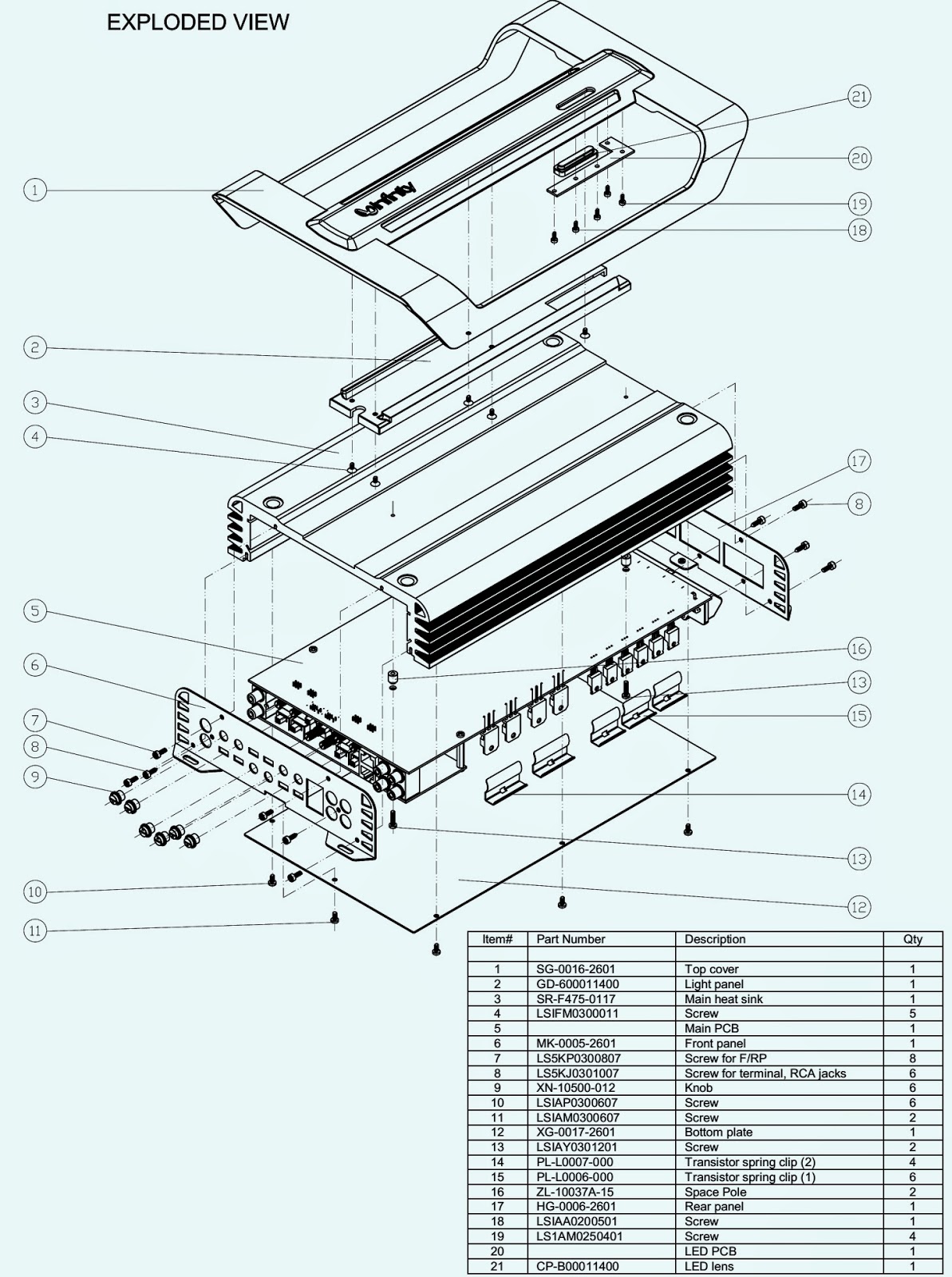
EXPLODED VIEW & PARTS
The main power transformer (toroid) part: 150-r1107010in the TSS-SUB4000 is not mounted in the amplifier inside the amp cover, but mounted in the cabinet in a separate location. To replace the power transformer, it is necessary to remove the woofer from the cabinet. The mounting bolt and transformer itself is mounted on an internal brace; both are accessible through the woofer opening.
Troubleshooting:
To keep the circuit “live” while exposing the amplifier components, the amplifier cannot completely be removed and powered up outside the cabinet due to the power connections to the externally mounted transformer. Instead, an alternate method is to leave the amp cover in place and remove the four Phillips screws holding the amp ass’y to the amp cover. Then the amplifier can be partially removed for access, while maintaining the power connections. Unplugging the LED connection (red/black wires) at the PCB plug will allow the amp to be removed even further.POWER AMP-SCHEMATIC {Click on the Schematic to Zoom In}
Specifications
Frequency Response 28Hz – 150Hz (–3dB) 24Hz – 180Hz (–6dB)
Maximum Amplifier Output 400 watts RMS (20Hz – 150Hz with no more than 0.1% THD)
Crossover Frequency 150Hz, 12dB/octave
Driver 12" (305mm) MMD®
Dimensions (H x W x D) 17-1/2" x 17-1/4" x 11-1/8" (445mm x 438mm x 283mm)
Weight 48 lb (21.8kg)
↧
↧
SANSUI HDLCD 1909 - HOW TO ENTER SERVICE MODE - LCD TV
CONFIRMATION OF INITIAL DATA {When replacing memory IC}
1. Turn on the POWER, and set to the ALL mode. ,
2. Set the VOLUME to minimum.
3. Press both VOL. DOWN button on the set and Channel button (8) on the remote control for more than 2 seconds.
4. After the confirmation of each check sum, turn off the power.
CONFIRMATION OF INITIAL DATA
CONFIRMATION OF CHECK SUM, POWER ON TOTAL HOURS AND MICON VERSION
Initial total of MEMORY IC, POWER ON total hours and MICON VERSION can be checked on the screen. Total hours are displayed in 16 system of notation. NOTE: If you set a factory initialization, the total hours is reset to "0".
If a service repair is undertaken where it has been required to change the MEMORY IC, the following steps should be taken to ensure correct data settings while making reference to INITIAL SETTING TABLE (Attached "INITIAL DATA").
1. Turn on the POWER, and set to the ALL mode.
2. Set the VOLUME to minimum.
3. Press both VOL. DOWN button on the set and Channel button (6)on the remote control for more than 2 seconds. 3. Press both VOL. DOWN button on the set and Channel button (6)on the remote control for more than 2 seconds.
ADDRESS and DATA should appear as FIG. NOTE: No need to set data other position than 0D00~0EFF.
4. ADDRESS is now selected and should "blink". Using the CH. UP/DOWN button on the remote, step through the ADDRESS
until required ADDRESS to be changed is reached.
5. Press VOL. UP/DOWN button to select DATA. When DATA is selected, it will "blink".
6 Again step through the DATA using CH UP/DOWN button until required DATA value has been selected
7. Pressing VOL. UP/DOWN button will take you back to ADDRESS for further selection if necessary.
8. Repeat steps 4 to 6 until all data has been checked.
9. When satisfied correct DATA has been entered, turn POWER off (return to STANDBY MODE) to finish DATA input. After the data input, set to the initializing of shipping.
10. Turn on the Power.
11. Set the VOLUME to minimum.
12. Press both VOL. DOWN button on the set and Channel button (1)on the remote control for more than 2 seconds.
13. After the finishing of the initializing of shipping, the unit will turn off automatically. The unit will now have the correct DATA for the new MEMORY IC.
SERVICE MODE
To enter to the SERVICE MODE function, press and hold both buttons simultaneously on the main unit and on the remote control for more than a the standard time in the appropriate condition.
↧
MITSUBISHI WS 55517 - PROJECTION TV - POWER SUPPLY SCHEMATIC
↧
GRUNDIG UMS-1 - UMS-2 - POWER AND AMPLIFIER SCHEMATIC (TDA7370 – NJM4556)
↧
SONY HCD-HX3/HX5/HX7 - COMPACT DISC RECEIVER_ POWER AMP SCHEMATIC
↧
↧
HOW TO RESET – SERVICE MODE - TEST MODE - UNLOCK - SONY HCD-HX3/HX5/HX7
SERVICE MODE
CD SERVICE MODE
This mode can run the CD sled motor freely. Use this mode, for instance, when cleaning the optical pick-up.
Procedure:
1. Press the POWER button to turn the power on.
2. Press the [FUNCTION]button to select “CD” (HX3/HX7). Press the [CD] button on the remote commander to select “CD” (HX5).
3. Press three buttons of [SEARCH], + and EJECT simultaneously, the message “SERVICE MODE” is displayed on the fluorescent indicator tube.
4. Press the – button to move the optical pick-up to inside track and the message “SLED IN” is displayed on the fluorescent indicator tube, or press the + button to outside track and the message “SLED OUT” is displayed on the fluorescent indicator tube.
5. Press the [DSGX] button, “LD ON” or “LD OFF” is displayed on the fluorescent indicator tube. Each time [DSGX] button is pressed, laser diode on/off is changed over.
6. To release this mode, press the POWER button.BT TEST MODE (HX5/HX7)
This mode is used to check the firmware version and address of bluetooth module.
Procedure:
1. Press the POWER button to turn the power on.
2. Press the [FUNCTION] button to select “BLUETOOTH” (HX7). Press the [FUNCTION] button on the remote commander to select “BLUETOOTH” (HX5).
3. Press three buttons of [SEARCH], – and [BLUTOOTH OPR] simultaneously, the message “BT Test” is displayed on the fluorescent indicator tube. Then, the display is automatically changed to the firmware version of bluetooth module.
4. Press the [DISPLAY] button, address of bluetooth module is displayed on the fluorescent indicator tube.
5. To release this mode, press the POWER button.
PANEL TEST MODE
This mode is used to check the fluorescent indicator tube, LED, model, destination, software version and key.
Procedure:
1. Press the POWER 1button to turn the power on.
2. Press three buttons CANCEL, [DSGX] and EJECT simultaneously.
3. All segments on the fluorescent indicator tube and [STANDBY]LED light up.
4. Press the [DSGX] button, the model and destination are displayed on the fluorescent indicator tube.
5. Press the [DSGX] button again, MC version is displayed on the fluorescent indicator tube.
6. Each time [DSGX] button is pressed, the display changes starting from MC version, GC version, USBL version (HX3/HX5 only), USBM version (HX3/HX5 only), BT version (HX5/HX7 only), CD version, CDD version, CDMA version, CDMB version, BDA version, BDB version, ST version, TA version and TM version this order, and returns to the MC version display.
7. When [SEARCH] button is pressed while the MC version is displayed, year, month and day of the software creation is displayed. When [SEARCH]button is pressed again, the display returns to the MC version display.
8. Press the [ENTER] button, the key test mode is activated and “K 0 V0” is displayed on the fluorescent indicator tube.
9. Each time a button is pressed, “K” value increases. However, once a button is pressed, it is no longer taken into account. All keys are pressed, display becomes “K17” (HX3) or “K18” (HX5/HX7).
10.“V” value increases 2, 4, 6 ... if turn the [VOLUME] knob clockwise, or it decreases 8, 6, 4 ... if turn the knob counterclockwise.
11.To release this mode, press three buttons in the same manner as step 2, or disconnect the power cord.
TUNER STEP CHANGE
(HX3: Canadian/HX5: Canadian, Australian, Korean/HX7)
A step of AM tuning interval can be changed over between 9 kHz or 10 kHz.
Procedure:
1. Press the POWER button to turn the power on.
2. Press the [TUNER/BAND]button to select “AM”.
3. Press the POWER button again to turn the power off.
4. Press two buttons of [TUNER/BAND] and POWER 1simultaneously.
5. The message “AM 9kHz Step” or “AM 10kHz Step” is displayed on the fluorescent indicator tube and thus the tuning interval is changed over.
CD SHIP MODE
This mode moves the optical pick-up to the position durable to vibration.
Procedure:
1. Press the POWER button to turn the power on.
2. Press the [FUNCTION]button to select “CD” (HX3/HX7). Press the [CD] button on the remote commander to select “CD” (HX5).
3. Press two buttons of [SEARCH] and POWER simultaneously.
4. After the “STANDBY” display blinks, “LOCK” is displayed on the fluorescent indicator tube, and the ship mode is set.
CD SHIP MODE & MEMORY CLEAR
This mode is used to perform CD ship mode and cold reset simultaneously.
Procedure:
1. Press the Power button to turn the power on.
2. Press three buttons of [SEARCH], [DSGX] and POWER simultaneously.
3. After the “STANDBY” display blinks, “LOCK” is displayed on the fluorescent indicator tube, the ship mode is set and the system is reset.ANTI-THEFT LOCK MODE
This mode is used to unable to take sample disc out of disc tray in the shop.
Procedure:
1. Press the POWER button to turn the power on.
2. Press the EJECT button to open the disc tray and set the CD disc.
3. Press the EJECT button to close the disc tray.
4. Press two buttons of CANCEL and EJECT for 5 seconds.
5. The message “LOCKED” is displayed on the fluorescent indicator tube and the disc tray is locked. (Even if pressing the EJECT button, the message “LOCKED” is displayed on the fluorescent indicator tube and the disc tray is locked)
6. To release from this mode, press two buttons of CANCEL and EJECT for 5 seconds.
7. The message “UNLOCKED” is displayed on the fluorescent indicator tube and the disc tray is unlocked.
COLD RESET
The cold reset clears all data including preset data stored in the RAM to initial conditions. Execute this mode when returning the set to the customer.
Procedure:
1. Press three buttons CANCEL , [DSGX] and POWER simultaneously.
2. The system is reset and becomes standby states.
CD POWER MANAGE
This mode is used to changed over CD power on/off for decreasing of reception noise in the tuner mode.
Procedure:
1. Press the POWER 1button to turn the power on.
2. Press the [FUNCTION]button to select “CD” (HX3/HX7). Press the [CD] button on the remote commander to select “CD” (HX5).
3. Press the POWER button again to turn the power off.
4. Press two buttons of CANCEL and POWER simultaneously.
5. The message “CD POWER ON” or “CD POWER OFF”is displayed on the fluorescent indicator tube, and CD power on/off is changed over in the tuner mode.
↧
HOW TO DISASSEMBLE SONY HCD-HX5 - COMPACT DISC RECEIVER
↧
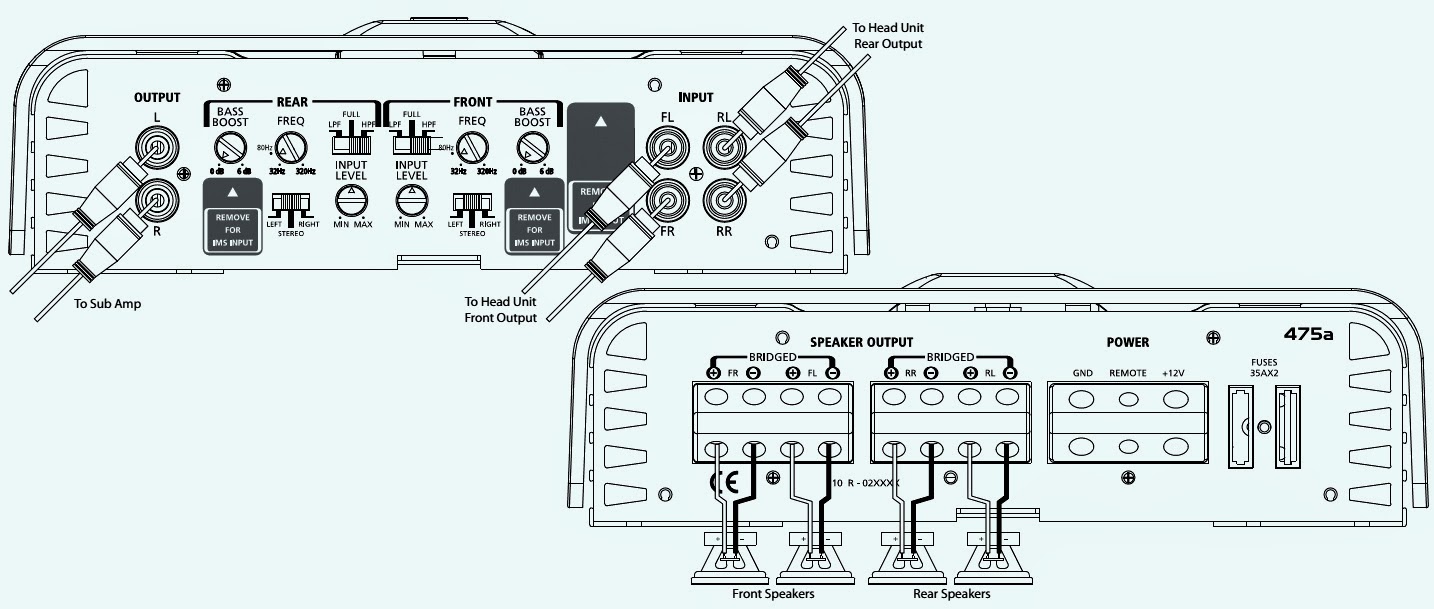
INFINITY ref-475a - 4,3,2 CHANNEL POWER AMPLIFIER - CONNECTION DIAGRAM
CONNECTIONS
The 475a can be set up for stereo 4-channel, 3-channel or bridged 2-channel operation.
NOTE: Minimum speaker impedance for stereo operation is 2 ohms. Minimum speaker impedance for bridged operation is 4 ohms.
Not all possible applications are shown here.Some applications should include a separate subwoofer driven by an additional amplifier.
475a connected to full-range speakers. Note crossover and channel assignment settings.
475a connected to four satellite speakers and used in conjunction with an additional subwoofer amplifier or powered sub-woofer. Note: crossover and channel assignment settings.
475a connected in tri-mode to a subwoofer and a pair of satellite speakers. Note: crossover and channel assignment settings.
ref-475a connected in bridge mode to a pair of full-range speakers. Note crossover and channel assignment setting.
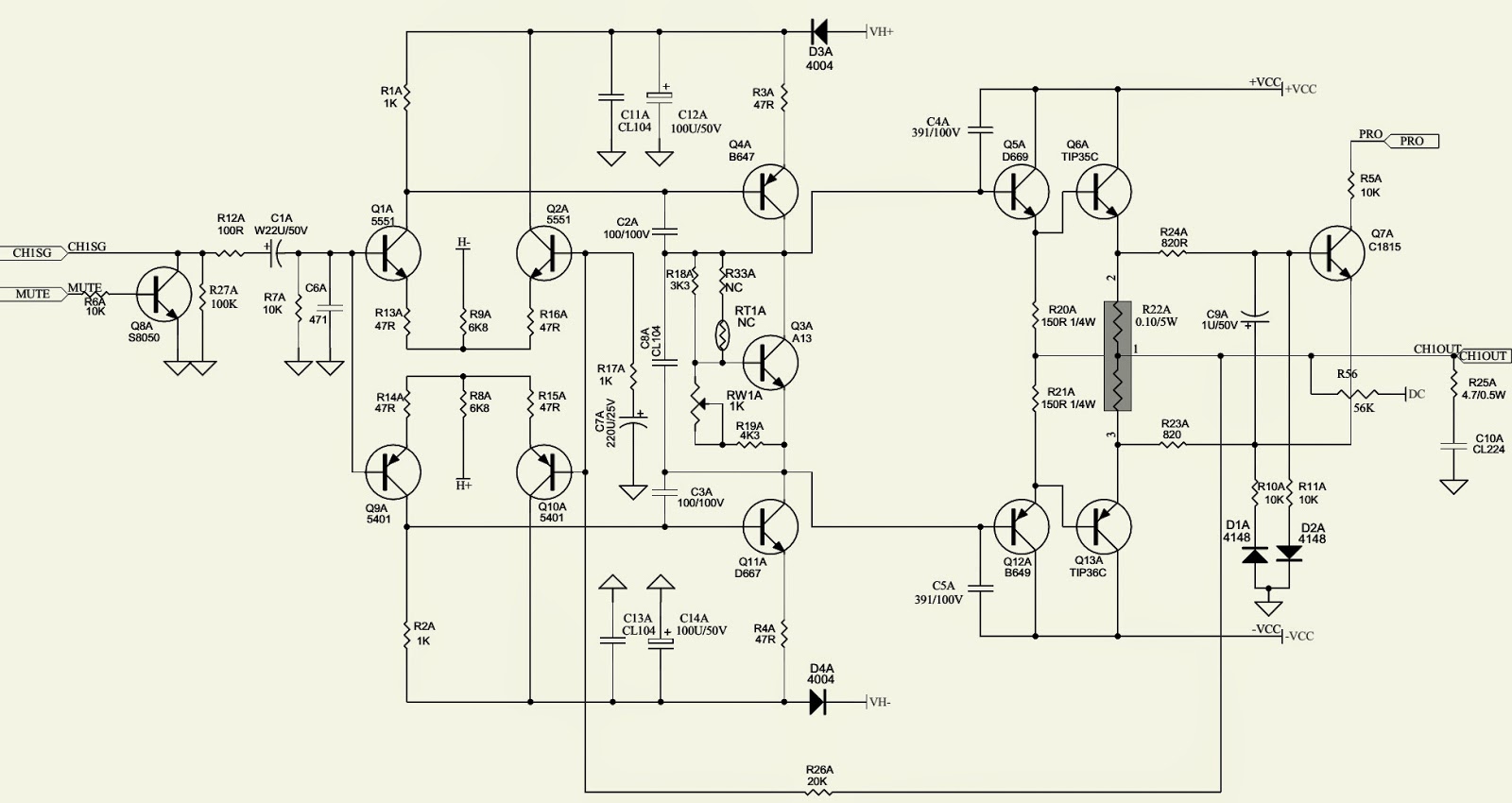
POWER AMPLIFIER SCHEMATIC (Only one channel is shown. All the others are similar)
↧
ref475a - INFINITY CAR AUDIO_CIRCUIT DIAGRAM [SCHEMATIC]
↧
↧
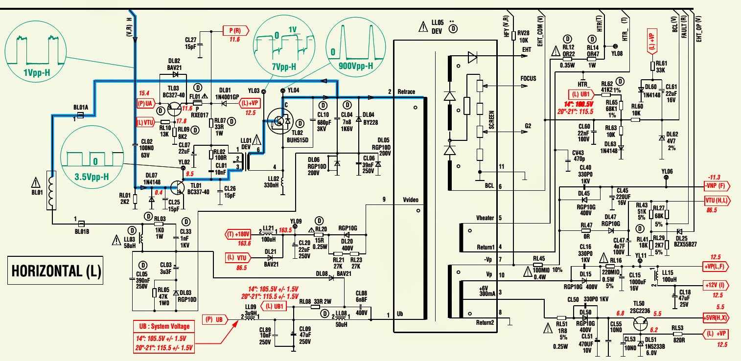
THOMSON TX8O7EU CRT TV - POWER-AUDIO-VIDEO&HORIZONTAL OUTPUT - SCHEMATIC
↧
SONY PMC-DR45L PERSONAL COMPONENT SYSTEM - POWER AMP SCHEMATIC [LA4705NA]
↧
HOW TO PROGRAM A DISH NETWORK REMOTE CONTROL TO OTHER DIVICES
PROGRAMMING PROCEDURE
COMBINATION EQUIPMENT (FOR EXAMPLE, TV/DVD)
When programming the remote control to operate combination equipment, such as a TV/DVD ora TV/VCR, program the remote control in one mode, and then repeat the procedure in the other mode. For example, to program the remote control to operate a TV/DVD player using code 765, follow the instructions to program the remote to operate the TV using code 765, and then repeat the instructions for the DVD using the same code. Put the remote in TV mode to use TV functions, or DVD mode to use the DVD player (or VCR) functions.LIMITED MODE
You can program your remote control in Limited Mode to keep from accidentally changing the channel on your TV or VCR. When you use the remote control to operate your TV in Limited Mode, you will only be able to use the POWER, MUTE, and Volume buttons to operate your TV. Also, when you use the remote control to operate your VCR in Limited Mode, you will only be able to use the Power and VCR function buttons. The section Programming Using the Equipment Code Tables has a step that tells the remote control to go into Limited Mode. Note: Limited Mode cannot be used with audio amplifiers.
PROGRAMMING USING EQUIPMENT CODE
You can set up the remote control to operate other equipment using the code.
Procedure:
1 Turn the equipment on. Use the equipment’s front panel buttons or its own remote control.
2 Find the brand name of the equipment listed in the code table. If the brand isn't listed in the tables, see Scanning for Equipment Codes.
3 Press and hold the mode button for the equipment until all the other mode buttons light up, and then release the button. The mode button flashes. For example, hold the TV mode button for a TV until all of the other mode buttons light. When you let go, the TV mode button will be flashing.
4 For AUX mode only. Press 0 for a second TV, or 1 for a second DVD/VCR, or 2 for a tuner, amplifier, or audio receiver. This step is for programming the kind of equipment that should be programmed in AUX mode. If you’re not programming in Aux mode, skip to step 5.
5 Enter one of the three-digit equipment codes from the table using buttons on the number pad. The three-digit equipment code should be for the brand name of your equipment that you found in step 2.
6 If you want to program Limited Mode, press 1. If not, skip to step 7.
7 Press POUND (#). If you entered the code correctly, the mode button flashes three times.
8 Press Power to turn off the equipment. If the equipment does not turn off, go to step 10. If the code you entered works, the equipment should turn off.
9 Turn the equipment back on and try some other buttons to make sure they work. If the code works for other buttons, stop here. For example, sometimes Power works when other buttons don’t. Note that more than one code may work to turn equipment on or off.
10 If the code doesn't work, repeat steps 3 through 9 with another equipment code listed. Try every code listed for your brand until one works for your equipment.
11 If you can’t find a code that works, try the instructions that follow for Scanning for Equipment Codes.
SCANNING.
1 Turn the equipment on. Use the equipment’s front panel buttons or its own remote control.
2 Press and hold the mode button until all the other mode buttons light up, and then release the button. The mode button flashes. For example, hold the V mode button for a TV until all of the other mode buttons light. When you let go, TV will flash.
3 For Aux mode only. Press 0 for a second TV, 1 for a second DVD/VCR, or 2 for a tuner, amplifier, or audio receiver. Then press the STAR (*) button. This step is for programming the kind of equipment that should be programmed in AUX mode. If you’re not programming in Aux mode, skip to step 4.
4 Press POWER. This puts your remote control in its code scanning mode.
5 Press either the UP or DOWN ARROW repeatedly until the equipment turns off. As you press the UPor DOWN ARROW, the remote tries each code in the memory to see if it can turn off your equipment. When the equipment turns off, you have found a code that might work. Note: The mode button for the equipment will flash rapidly eight times when you've scanned through all the codes for that equipment.
6 Press POUND (#). The mode button flashes three times if you have entered the code correctly. This stores the code that you found.
7 Turn the equipment back on and try some other buttons to make sure they work. Press POWER to turn the equipment back on. Try some other buttons to make sure they work. Sometimes POWER works when other buttons don’t, and more than one code may work to turn equipment on or off.
8 If necessary, repeat this procedure until you've tried all the codes. You may need to repeat the scan to find the best code for your equipment.
SWITCHING BETWEEN TV AND AMPLIFIER VOLUME CONTROL
When the remote control is set up to operate your TV, the MUTEand VOLUMEbuttons will adjust your TV volume. To use the remote to adjust the volume of a remote-controllable audio receiver or amplifier instead of adjusting the TV’s volume setting, use the steps in the left column of the table. To switch backto controlling the TV’s volume, steps are also given.
Control Amplifier Volume
1 Press and hold the AUX mode button until all mode buttons are lit, then release it. The AUX mode button will blink.
2 Press the POUND (#) button.
3 Press the plus (+) side of the VOLUME button.
4 Press the 0number button.
5 Press the POUND (#) button. The AUX mode button flashes three times. MAKE SURE THE REMOTE CONTROLS THE AMPLIFIER’S VOLUME IN OTHER MODES:
6 Press the SAT mode button.
7 Press the plus (+) and minus (-) sides of the VOLUME button.
8 Your tuner/amplifier’s volume changes and the AUX mode button lights instead of the TV mode button.
To Control TV Volume
1 Press and hold the TV mode button until all mode buttons are lit, and then release it. The TV mode button will blink.
2 Press the POUND (#) button.
3 Press the plus (+) side of the VOLUME button.
4 Press the 0 number button.
5 Press the POUND (#) button. The TV mode button flashes three times. MAKE SURE THE REMOTE CONTROLS THE TV’S VOLUME IN OTHER MODES:
6 Press the SAT mode button.
7 Press the plus (+) and minus (-) sides of the VOLUME button.
8 Your TV’s volume changes and the TV mode button lights instead of the AUX mode button.
PROGRAMMING THE REMOTE TO CONTROL ASECOND RECEIVER IN AUX MODE
If you have another DISH Network receiver installed, you can use this remote control in AUX mode to operate it along with your new receiver. When you program the remote control to operate the other receiver, the remote will send IR signals to that receiver, so the line of sight to the second receiver must be unobstructed. You can program the remote control to operate any other DISH Network receiver, except for: TV2 on DISH 322, DISH Player-DVR models 522, 625, and 942, ViP222, ViP222k, ViP622 DVR, ViP722 DVR or ViP722k DVR.
Dish Player 7100/7200
1 Turn on the other receiver and open the System Information screen. (For help opening the System Information screen, refer to the user guide for the other receiver.) Write down the TV2 address shown:
2 Press and hold the AUX button until all the mode buttons light up, and then release the button. The AUX button flashes.
3 Use the NUMBER PAD on the remote control to enter a 3, followed by the address you wrote down in step 1.
4 Press POUND (#). The AUX button blinks three times.
5 Press RECORD to verify that the address in the remote control now matches the address for the receiver.↧


