↧
32PFL5332 - PHILIPS MAGNAVOX - AUDIO & DC to DC CONVERTER SCHEMATIC
↧
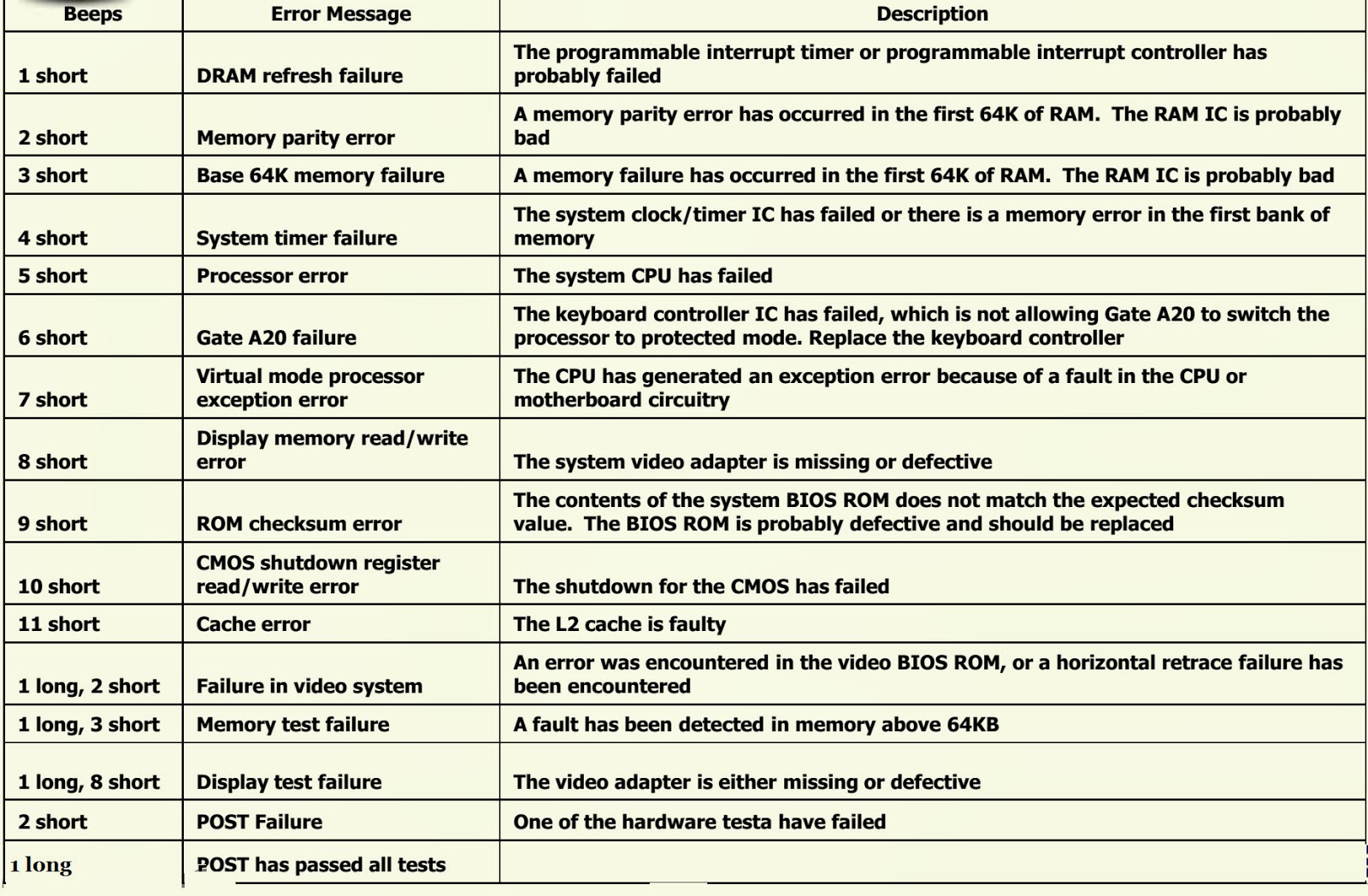
ASUS NOTEBOOK - BIOS Beep Codes - AMI - AWARD - PHOENIX
↧
↧
TCL 24D10 MT23 _ L32D10 MT23-LCD TV - HOW TO ENTER SERVICE MODE - ADJUSTMENTS
FACTORY MODE [SERVICE MODE]
Method one˖ In any sources enter to the menu, move the cursor to “Contrast” item then press the “9”, “7”, “3”, “5” keys continuously on the remote control. Service mode screen will be displayed.
Method-2: In the production of the factory menu, if set “FacMode” and “FacHotkey” as “ON”. There is a “P” on the left corner of the panel. In this status, can enter the factory menu by pressing the “Return” key, by remote control. In the factory menu, you can return to the previous menu by the “Menu” key of the RC.To Exit Factory mode
* Press the ‘Exit' key on the remote control.
* Press the ‘Menu” key on the remote control, to go back to the previous menu.
* Press the ‘Menu” key on the remote control, to go back to the previous menu.
. * If the hotkey of factory menu is “On” the status cannot be changed by turn off the TV. You need to change the hotkey to factory “OFF”
* “Shop Init” should be don at the last alignment.
* “Shop Init” should be don at the last alignment.
↧
HP - COMPUTER BIOS BEEP CODES
BIOS BEEP-CODES
What to do when beep codes occur
Listen to the beeping sound and write down the number of beeps before each pause, if the beeps are long or short, or if the beeps high or low in tone. Once a pattern is determined, use the following beep code table to identify which component might be causing the problem: Use these codes to help troubleshoot problems related to system start-up or flashing BIOS memory (such as in BIOS upgrades). When troubleshooting further, refer to the section What to do when beep codes occur .
Four series of beeps indicate a fatal error; that is, a problem exists which prevents the computer from starting. For example, there might be two beeps, a short pause, one beep, a short pause, one beep, a short pause, and then three beeps; this is represented as:
Four series of beeps indicate a fatal error; that is, a problem exists which prevents the computer from starting. For example, there might be two beeps, a short pause, one beep, a short pause, one beep, a short pause, and then three beeps; this is represented as:
1 short beep and 1 long beep : Memory problem
2 short beeps and 1 long beep (repeats 5 times) : Unable to initialize video or video card required but not installed
3 short beeps and 1 long beep : CPU configuration error or CPU type is not compatible
The following beep codes can occur while restoring, flashing or updating the BIOS:
1short beep : Legacy floppy drive or CD/DVD drive not detected
2short beeps : Floppy diskette or compact disc not detected
3short beeps : Unable to start flashing (such as when missing a utility or BIOS image)
4short beeps : Flashing failed (checksum error, corrupted image, etc.)
5short beeps : BIOS recovery successful
Perform the following steps to resolve beeping issues. Before starting a task, turn off the computer, and then remove the power cord. After completing a task, replace any covers, reconnect the power cord, turn on the computer, and then listen for a beep code.
* Remove any media from the floppy drives, CD/DVD drives, USB ports, and memory card reader slots, and disconnect all non-essential devices (printers, scanners, external hard drives, and similar).
* Disconnect the mouse and keyboard, and then restart the computer. If the beeping sound stops, repair or replace those devices.
* Hot air can damage internal components! Remove any obstructions that block vents. Clean the cooling vents on the case to remove dust. If cooling fans stop spinning or make strange noises, service the computer.
* Remove the memory cover, and then re-seat all memory modules. If the computer stops beeping, a memory module might not have been fully seated or connected.
If the computer has multiple memory modules, turn on the computer with only one memory module installed. If the computer stops beeping, the memory module might be defective, or might be the wrong type of memory for the motherboard. Reinsert the memory into the socket to see if a connection was the problem; otherwise replace the module. Repeat this process for all memory modules installed in the computer If all of the above steps have been tried and the beeping sound still exists, refer to beep code table specific to the motherboard of the computer
Beep codes for American Megatrends, Inc (AMI) bios.
The following AMI beep codes can occur when there is a problem during the attempt of a normal system start-up. Use these codes to help troubleshoot problems related to system start-up. When troubleshooting further.
1 beep : Memory timing failure
2 beeps : Memory parity error
3beeps : Memory read or write failure
4, 5, 6, 7 : Fatal errors related to the operation of critical motherboard components - such as the CPU.
8 beeps : Video memory
AMI beep codes that can occur when attempting to flash or recover the BIOS. You can use these codes to help troubleshoot problems related to system start-up or flashing BIOS memory (such as in BIOS upgrades).
1beep : No media detected
2beeps : ROM file not found in root directory
3beeps : Insert next media volume
4beeps : Flash Programming successful
5beeps : Failure while reading file
7beeps : Flash EPROM not detected
10beeps : Failure while erasing flash memory
11beeps : Flash program error
12beeps : Problem with ROM file size
13beeps : ROM image does not match BIOS requirements
Beep codes for Phoenix BIOS
Four series of beeps indicate a fatal error; that is, a problem exists which prevents the computer from starting. For example, there might be two beeps, a short pause, one beep, a short pause, one beep, a short pause, and then three beeps.
eps | Post Code | Description of failure |
One short beep | 0 | POST process completed successfully - normal startup |
1-1-1-3 | 02h | Verify real mode |
1-1-2-1 | 04h | Get CPU type |
1-1-2-3 | 06h | Initialize system hardware |
1-1-3-1 | 08h | Initialize chipset registers with initial POST values |
1-1-3-2 | 09h | Set in POST flag |
1-1-3-3 | 0Ah | Initialize CPU registers |
1-1-4-1 | 0Ch | Initialize cache to initial POST values |
1-1-4-3 | 0Eh | Initialize I/O |
1-2-1-1 | 10h | Initialize Power Management |
1-2-1-2 | 11h | Load alternate registers with initial POST values |
1-2-1-3 | 12h | Jump to UserPatch0 |
1-2-2-1 | 14h | Initialize keyboard controller |
1-2-2-3 | 16h | BIOS ROM checksum |
1-2-3-1 | 18h | 8254 timer initialization |
1-2-3-3 | 1Ah | 8237 DMA controller initialization |
1-2-4-1 | 1Ch | Reset Programmable Interrupt Controller |
1-3-1-1 | 20h | Test DRAM refresh |
1-3-1-3 | 22h | Test 8742 Keyboard Controller |
1-3-2-1 | 24h | Set ES segment register to 4 GB |
1-3-3-1 | 28h | Autosize DRAM |
1-3-3-3 | 2Ah | Clear 512K base RAM |
1-3-4-1 | 2Ch | Test 512 base address lines |
1-3-4-3 | 2Eh | Test 512K base memory |
1-4-1-3 | 32h | Test CPU bus-clock frequency |
1-4-2-1 | 34h | CMOS RAM read/write failure |
1-4-2-4 | 37h | Reinitialize the chipset |
1-4-3-1 | 38h | Shadow system BIOS ROM |
1-4-3-2 | 39h | Reinitialize the cache |
1-4-3-3 | 3Ah | Autosize cache |
1-4-4-1 | 3Ch | Configure advanced chipset registers |
1-4-4-2 | 3Dh | Load alternate registers with CMOS values |
2-1-1-1 | 40h | Set Initial CPU speed |
2-1-1-3 | 42hs | Initialize interrupt vector |
2-1-2-1 | 44h | Initialize BIOS interrupts |
2-1-2-3 | 46h | Check ROM copyright notice |
2-1-2-4 | 47h | Initialize manager for PCI Options ROMs |
2-1-3-1 | 48h | Check video configuration against CMOS |
2-1-3-2 | 49h | Initialize PCI bus and devices |
2-1-3-3 | 4Ah | Initialize all video adapters in system |
2-1-4-1 | 4Ch | Shadow video BIOS ROM |
2-1-4-3 | 4Eh | Display copyright notice |
2-2-1-1 | 50h | Display CPU type and speed |
2-2-1-3 | 52h | Test keyboard |
2-2-2-1 | 54h | Set key click if enabled |
2-2-2-3 | 56h | Enable keyboard |
2-2-3-1 | 58h | Test for unexpected interrupts |
2-2-3-3 | 5Ah | Display prompt "Press F2 to enter SETUP" |
2-2-4-1 | 5Ch | Test RAM between 512 and 640k |
2-3-1-1 | 60h | Test expanded memory |
2-3-1-3 | 62h | Test extended memory address lines |
2-3-2-1 | 64h | Jump to UserPatch1 |
2-3-2-3 | 66h | Configure advanced cache registers |
2-3-3-1 | 68h | Enable external and CPU caches |
2-3-3-2 | 69h | Initialize SMI handler |
2-3-3-3 | 6Ah | Display external cache size |
2-3-4-1 | 6Ch | Display shadow message |
2-3-4-3 | 6Eh | Display non-disposable segments |
2-4-1-1 | 70h | Display error messages |
2-4-1-3 | 72h | Check for configuration errors |
2-4-2-1 | 74h | Test real-time clock |
2-4-2-3 | 76h | Check for keyboard errors |
2-4-4-1 | 7Ch | Set up hardware interrupts vectors |
2-4-4-3 | 7Eh | Test coprocessor if present |
3-1-1-1 | 80h | Disable onboard I/O ports |
3-1-1-3 | 82h | Detect and install external RS232 ports |
3-1-2-1 | 84h | Detect and install external parallel ports |
3-1-2-3 | 86h | Re-initialize onboard I/O ports |
3-1-3-1 | 88h | Initialize BIOS data area |
3-1-3-3 | 8Ah | Initialize extended BIOS data area |
3-1-4-1 | 8Ch | Initialize floppy controller |
3-2-1-1 | 90h | Initialize hard-disk controller |
3-2-1-2 | 91h | Initialize local-bus hard-disk controller |
3-2-1-3 | 92h | Jump to UserPatch2 |
3-2-2-1 | 94h | Disable A20 address line |
3-2-2-3 | 96h | Clear huge ES segment register |
3-2-3-1 | 98h | Search for option ROMs |
3-2-3-3 | 9Ah | Shadow option ROMs |
3-2-4-1 | 9Ch | Set up Power Management |
3-2-4-3 | 9Eh | Enable hardware interrupts |
3-3-1-1 | A0h | Set time of day |
3-3-1-3 | A2h | Check key lock |
3-3-3-1 | A8h | Erase F2 prompt |
3-3-3-3 | Aah | Scan for F2 key stroke |
3-3-4-1 | AChP | Enter SETUP |
3-3-4-3 | Aeh | Clear in-POST flag |
3-4-1-1 | B0h | Check for errors |
3-4-1-3 | B2h | POST done--prepare to boot operating system |
3-4-2-1 | B4h | One beep |
3-4-2-3 | B6h | Check password (optional) |
3-4-3-1 | B8h | Clear global descriptor table |
3-4-4-1 | BCh | Clear parity checkers |
3-4-4-3 | Beh | Clear screen (optional) |
3-4-4-4 | BFh | Check virus and backup reminders |
4-1-1-1 | C0h | Try to boot with INT 19 |
4-2-1-1 | D0h | Interrupt handler error |
4-2-1-3 | D2h | Unknown interrupt error |
4-2-2-1 | D4h | Pending interrupt error |
4-2-2-3 | D6h | Initialize option ROM error |
4-2-3-1 | D8h | Shutdown error |
4-2-3-3 | Dah | Extended Block Move |
4-2-4-1 | DCh | Shutdown error |
4-2-4-3 | Deh | Keyboard Controller Failure |
4-3-1-3 | E2h | Initialize the chipset |
4-3-1-4 | E3h | Initialize refresh counter |
4-3-2-1 | E4h | Check for Forced Flash |
4-3-2-2 | E5h | Check HW status of ROM |
4-3-2-3 | E6h | BIOS ROM is OK |
4-3-2-4 | E7h | Do a complete RAM test |
4-3-3-1 | E8h | Do OEM initialization |
4-3-3-2 | E9h | Initialize interrupt controller |
4-3-3-3 | Eah | Read in bootstrap code |
4-3-3-4 | Ebh | Initialize all vectors |
4-3-4-1 | Ech | Boot the Flash program |
4-3-4-2 | Edh | Initialize the boot device |
4-3-4-3 | Eeh | Boot code was read OK |
↧
CROWN - XLS602 – XLS402 – XLS202 - AMP - SCHEMATIC (Circuit Diagram)
↧
↧
DENON ASD-1R - CONTROL DOCK for iPod – SCHEMATIC (Circuit Diagram)
↧
INTEGRA DTM5.3 - SCHEMATIC (Circuit Diagram) - 2SC5200(NPN) – 2SA1943(PNP) – OUTOUT TRANSISTORS
↧
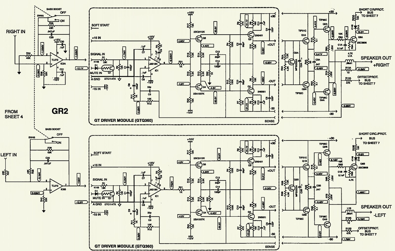
JBL JTQ360 - CAR AUDIO - SCHEMATIC [Circuit Diagram]
↧
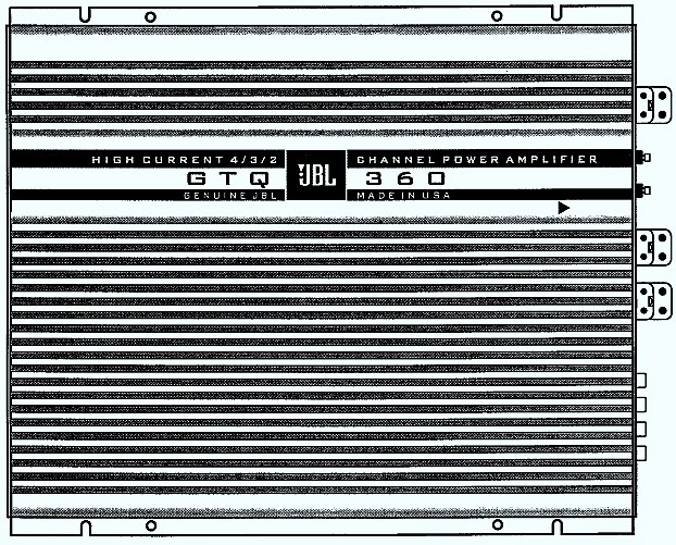
WIRING DIAGRAM - JBL JTQ-360 CAR STEREO
↧
↧
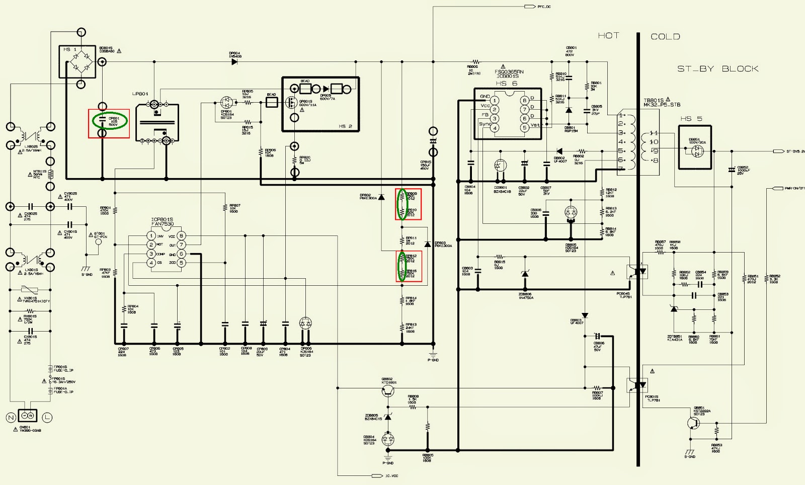
SAMSUNG LCD TV POWER SUPPLY - BN44-0020 - SCHEMATIC
↧
CW5944 - SAMSUNG COLOR TV - SMPS SCHEMATIC - (STR-KA3S1265R)
↧
HOW TO ENTER SERVICE MODE - WHITE BALANCE ADJUSTMENT - SAMSUNG CW593CWG8XXEG - CW5944N8XXEC - CW5944W8XXEG - CW683CNG8XXEC
APPLICABLE TO SAMSUNG CW593CWG8XXEG - CW5944N8XXEC - CW5944W8XXEG - CW683CNG8XXEC CTV
SERVICE MODE
To enter the “Service Mode”, Press the remote-control keys in this sequence :
If you do not have Factory remote-control;
If you do not have Factory remote-control;
PICTURE OFF> DISPLAY > MENU> MUTE> PICTURE ON.
If you have Factory remote-control:
PICTURE ON> DISPLAY> FACTORY
After the Service Mode is entered, the initial screen is as shown in the figure below. (These hexa digits are check sum value which depends on the MICOM. If check sum value is changed, the value ofE2PROM Data newly initialed.)
Use the Channel Up/Down buttons to move the cursor in the adjustment parameters. When CRT, CRT PCB, FBT, E2PROM (sometimes MICOM) is replaced, the adjustment values should be controlled. After the Service adjustment is completed, Do not select “Reset” in the service mode menu. (After above procedure is done, power is on initially and the “Plug and Play” will be operated.)MEMORY DATA: DEFLECTION (GEOMETRIC VALUE)
WHITE BALANCE ADJUSTMENT
1. Select STANDARD from the menu.
2. Input an 100% White pattern.
3. Enter the “Service Mode”.
4. Warm up the TV set at least for 30 minutes.
5. Input a Toshiba pattern signal.
6. Enter the “Video Adjust1”.
> Adjust “Sub Contrast” so that Y (luminance) becomes 40 ft ± 3.
> Use “Red Drive” and “ Blue Drive” to adjust High-Light (x : 290, y : 300)
> Adjust “Sub Bright” so that Y (luminance) becomes 1.3ft ± 0.3.
> Use “Red Cutoff” and “Blue Cutoff” to adjust Low-Light (x : 290, y : 300).
7. Adjust CA-100 so that the final adjustment value can be fixed.
8. Use the Channel Up/Down (▲/▼) buttons to move the cursor on the adjustment modes.
9. Use the Volume +/- buttons to change the adjustment value.
E2PROM (IC902) Replacement
1. When IC902 is replaced, all adjustment data revert to the initial values. So, all adjustment values when servicing should be readjusted.
2. After IC902 is replaced, connect the AC power supply cord.
3. Turn the power switch ON.
4. In stand-by, warm up the TV for at least 10 seconds.
5. Power on the TV.
↧
PLASMA TV - SAMSUNG PS42E7SX/XEC PDP-TELEVISION (P_Europe_42SD) TROUBLESHOOTING
COMMON ISSUES RELATED TO OTHER COMPONENTS [FOR MORE DETAILED DESCRIPTIONS; REFER THE NEXT POST HERE]
* A fixed screen can cause permanent damage to the TV Braun tube: Braun, PDP and LCD TVs can all be damaged. When a still image is displayed in a sequence, this can leave stains or after-images due to the characteristics of the panel. However, the DLP TV has the advantage that no stains or after-images are left on the screen. The DLP TV has mirror pixels on the DMD panel that project the beam onto the screen, in which the mirror is a digital representation of 0s and 1s, leaving no trace of light. The mirror returns to a blank state so that no stains or after-images are left.
* Length of DVI Cable / PC RGB Cable: A too long DVI cable may cause a malfunction or degradation of the visual quality due to an attenuation of the signal. There is no recommendation for the cable length at present. In general, although a cable length of up to 5 meters should work, please check if video is
* properly displayed on the screen after connecting. If you think the length of the cable is longer than for normal use, check the visual quality of the video on the screen and shorten the length, if necessary. This also applies to the PC RGB (D-Sub) cable. When the length of the cable is longer than for normal use, video may not be displayed on the screen. In this case, shorten the cable length.
* When a digitally distributed TV user receives HD-rated broadcasts: The digital distributed TV (Ready Technique) can render HD sources as HD-rated.
* However, you need to install a set-top box for this purpose. The digital TV alone cannot render HD broadcasting as HD-rated. Install the formal set-top box for HD broadcasts.
* When a digital distributed TV user selects normal size (4:3) to receive SD-rated digital broadcasts: The digitally distributed TV (Ready Technique) renders any broadcasting service as SD-rated. However, when connected to a set-top box, the digital TV renders HD broadcasts as HD-rated and renders SD as SD-rated. The screen size is scaled to 4:3.
* When a digitally built-in TV user receives SD (air) broadcasting: The digitally integrated TV ("built-in" type) renders SD broadcasting as SD-rated. This can be understood easily. Even a high-resolution TV cannot improve a low resolution picture into high quality. In contrast, an SD-rated TV cannot represent HD broadcasting as HD because the resolution of the TV is lower than the original.
* When selecting a picture size of 4:3 in connection with a computer or a multimedia device: The representation capability of SD or HD-rated depend entirely on the TV set. The HD TV can render HD broadcasting as HD-rated only when it receives HD sources. In the meantime, the HD TV renders SD as SD-rated when it receives SD sources. The picture size has nothing to do with the resolution; TV models like SVP-XXL3HD or SVP-XXL6HD have a size adjustment feature to 16:9, 4:3, Panorama, Zoom1, Zoom2 and Auto Wide. This is about the aspect ratio of the top and bottom boundaries to the overall screen and users can select their preference.SD/HD broadcasts and the TV's display capability are related.
1. A digital broadcast should be transmitted in wide screen (an aspect ratio of 16:9) HD. If the broadcasting station converts a conventional program created in normal screen (aspect ratio of 4:3) into a digital signal and broadcasts the signal, the left and right of the picture will not be displayed. This symptom also appears in other manufacturer's TV's. The three appliance companies are trying to resolve the problem through the Ministry of Information and Communication.
> When watching an SD (normal) broadcast through a Digital (Wide) TV (480P normal broadcast)
> When watching an SD (normal) broadcast through a Digital Ready (Wide) TV (Using a set-top-box)
> When watching an analog (normal) broadcast through a wide TV. (When watching a broadcast after changing the aspect ratio of the TV from 16:9 (wide screen) to 4:3)
2. When watching a DVD title or video tape in wide screen (21:9) through a wide (16:9) TV, watching video from a computer or game console by selecting the aspect ratio to 4:3, or watching video from a DVD, VCR, computer or game console through a wide TV by selecting the aspect ratio to normal (4:3) or wide (21:9), the left and right, or top and bottom of the picture will not be displayed. This symptom appears in other manufacturer's TV's. The three appliance companies are trying to resolve the problem through the Ministry of Information and Communication.
Changing the Order of the Picture Size for 16:9 Display Devices.
1. When you want to change the picture size in PIP 'ON', you must turn the PIP off before changing the size. However, you can change the main picture size even in PIP ON for products with no restrictions.
2. When the picture size is not Normal (4:3 for 4:3 display devices, 16:9 for 16:9 display devices) and you turn PIP on, the picture size is changed to Normal. However, you can turn PIP on without changing the picture size for products with no restrictions.
3. In the OSD notation for the picture size, 16:9 is represented as "Wide" instead of "16:9" for devices other than with 16:9 displays. Ex: For LCD 15:9 devices, "Wide" is displayed on the OSD instead of "16:9".
4. The picture size can be changed even in the blue screen. However, the picture size should be controlled by the product specifications if the change is impossible due to hardware restrictions.
↧
↧
TROUBLESHOOTING - SAMSUNG PS42E7SX _ PLASMA TV
CHECK POINTS BY ERROR MODE
Symptom:
* The LEDs on the front panel do not work when connecting the power cord.
**The SMPS relay does not work when connecting the power cord.
*** The power of the unit seems to be out of order.
Major Checklist
The SMPS relay or the LEDs on the front panel do not work when connecting the power cord if the cables are improperly connected or the Main Board or SMPS is out of order. In this case, check the following:
* Check the internal cable connection status inside the unit.
** Check the fuses of each part.
*** Check the output voltage of SMPS.
**** Replace the Main Board.When the unit is repeatedly turned on and off
In general, the SMPS relay repeatedly turns on and off by the protection function due to a defect on a board connected to the SMPS.
* Disconnect all cables from the SMPS, operate the SMPS alone and check if the SMPS works properly and if each voltage output is correct.
** If the symptom continues even when SMPS is operated alone, replace the SMPS.
If the symptom is not observed when operating the SMPS alone, find any defective ASSYs by connecting the cables one by one.
When separating and connecting the cables such as CN809 of the Main SMPS, CN1, CN2, CN3, CN4 and CN5 of DC-DC SMPS, CN of the X Main Board, and CN of the Y Main Board, a spark may be generated by the electric charge of the high capacity capacitor. Therefore, wait some time after separating the power cord from the unit.
↧
NO PICTURE-AUDIO NORMAL - SAMSUNG PS42E7SX PLASMA TV
NO LIGHT_AUDIO IS NORMAL
This may happen when the Main Board is normal but the X, Y Main Board, Logic Board, or Y Buffer Board is out of order.
The output voltage of the Main SMPS or the DC-DC SMPS is out of order.
This may happen when the LVDS cable connecting the Main Board and the Logic Board is disconnected.When separating and connecting the cables such as CN809 of the Main SMPS, CN1, CN2, CN3, CN4 and CN5 of the DC-DC SMPS, CN of the X Main Board, and CN of the Y Main Board, a spark may be generated by the electric charge of the high capacity capacitor. Therefore, wait some time after separ ating the power cord from the unit.
NO SOUND
NO VIDEO
↧
PLASMA TV - TROUBLESHOOTING - SAMSUNG
MAIN SMPS TROUBLESHOOTING (Click on the images to Zoom In)
DRIVE BOARD TROUBLESHOOTING
TROUBLESHOOTING PROCEDURE IN ABNORMAL CONDITIONS
DRIVE BOARD TROUBLESHOOTING
TROUBLESHOOTING PROCEDURE IN ABNORMAL CONDITIONS
No Display (Operating Voltage exist, but an doesn't exist on Screen)
No Display is related with Y-MAIN, X-MAIN, Logic Main and so on.
Shows you how to check the boards, and the following pages show you how to find the defective board.
Abnormal Display is related with Y-MAIN, X-MAIN, Logic Main and so on. Shows you how to check the boards, and the following pages show you how to find the defective board.
SUSTAIN OPEN & SUSTAIN SHORT CONDITIONS
Address Open, Short(some vertical lines don't exist on screen) Address Open and Short is related with Logic Main, Logic Buffer, FFC, TCP film and so on.
Shows you how to check the boards, and the following pages show you how to find the defective board.
↧
42 INCH PLASMA TV - SAMSUNG - TROUBLESHOOTING PROCEDURE BY ASS'Y
↧
↧
VIEWSONIC VLCDS23719-1W [VG700] - TROUBLESHOOTING PROCEDURE
↧
HOW TO ENTER SERVICE MODE - PANASONIC TX-32LXD500 - TX-26LX500F – LED BLINKING CODES - WIDE LCD TV
APPLICABLE TO: PANASONIC TX-32LXD500_TX-26LXD500_TX-32LX500F_TX-32LX500P_TX-26LX500F_TX-26LX500P [LH41 Chassis]
SERVICE MODE
SERVICE MODE
MPU controls the functions switching for each IICs through IIC bus in this chassis. The following setting and adjustment can be adjusted by remote control in Service Mode.
How to enter SERVICE 1
1. In main menu, move to choose sound menu, set BASS to MAXIMUM, and set TREBLE to MINIMUM.
2. Simultaneously press INDEXbutton on remote control and DOWN button on the TV set.How to enter SERVICE 2
1. Enter the SERVICE 1 mode.
2. Set the channel to CH 99.
3. Press HOLD button on remote control.
To exit from Service mode, press N or Power button on remote control.
SERVICE-1
SERVICE-2
POWER LED BLINKING CODES [Fault Codes]
When an abnormality has occurred the unit, the protection circuit operates and reset to the stand by mode. At this time, the defective block can be identified by the number of blinking of the Power LED on the front panel of the unit.
↧
SERVICE MODE - ADJUSTMENTS - NEC INTEGRA-PX50XM1A – PX50XM1G - PLASMA DISPLAY
SERVICE MODE & ADJUSTMENTS
1. When the PDP module is replaced, adjust the sections according to the adjusting items 1 to 4 specified below.
2. When the power unit is replaced, adjust the sections according to the adjusting items 1 to 3 specified below.
3. When the MAIN PWB or the VIDEO PWB is replaced, adjust the sections according to the adjusting item 4 specified below.
4. No adjustments are required in case of any replacement other than 1 and 2 above.
{CAUTION} When you exchange PDP module, please be sure to clear integrated time to “0” by the following “How to clear the integrated time”.How to clear the integrated time
Assume the following factory mode by the use of the remote control. Press “PROCEED” key six times to get the screen of “USAGE TIME”. In this state, the integrated time up to the present time is displayed.
The integrated time is cleared to “0” when the remote control keys are pressed in the order of “MUTE” →POSITION “UP” →POSITION “DOWN” →“OFF TIMER”.
How to enter or withdraw from the factory setting mode:
Press the keys in the sequential order of [OFF TIMER] →[EXIT] →[MUTE] →[OFF TIMER].
When a conventional remote control is used:
Press the keys in the sequential order of [OFF TIMER] →[OK] →[MUTE] →[OFF TIMER].
At that time, use the [MENU] key in place of the [PROCEED] key.1. Adjustment of +170V
(1) Using any video signal of VIDEO input, DVD/HD input, or RGB input, and display a color bar signal. Turn on the power switch of the main unit.
(2) Turn the volume control (RV4) in the [+170V ADJ] section of the power unit, and adjust the voltage value between TP3 (+170V output) and TP4 (GND) of the power unit so that this voltage settles within the range of “specified voltage of the PDP module (Value Vs on the label shown below) ±1V.”
2. Adjustment of +70V
(1) Using any video signal of VIDEO input, DVD/HD input, or RGB input, and display a color bar signal. Turn on the power switch of the main unit.
(2) Confirm that the voltage value between TP2 (+70V output) and TP4 (GND) of the power unit is maintained at “70 ±1V.” Otherwise, turn the volume control (RV3) in the [D+70V ADJ] section so that the voltage value is maintained at “70 ±1V.”
3. Adjustment of +5V
(1) Use any video signal of VIDEO input, DVD/HD input, or RGB input, and display a color bar signal.
(2) Confirm that the voltage value between TP1 (+5V output) and TP4 (GND) of the power unit is maintained at “5.1 ±0.1V.” Otherwise, turn the volume control (RV2) in the [+5V ADJ] section so that the voltage value is maintained at “5.1 ±0.1V.”
4. Screen position and phase adjustment
Adjustment of the range of horizontal display presented at the PDP module
Adjustment of the range of vertical display presented at the PDP module
Adjustment of the signal position in horizontal direction within the H POS display range
Adjustment of the signal position in vertical direction within the V POS display range.
Adjustment of the VIDEO screen position
Make correct adjustments of the display range with [MHPOS] and [MVPOS].
(1) Enter an input of NTSC monoscopic signal in the VIDEO input terminal.
(2) Select the VIDEO input by the use of the relevant key of the remote control or the CTL PWB.
(3) Enter the factory shipment setting mode by using the factory shipment control command of the remote control.
(4) Press the [PROCEED] key to obtain the [POSITION] screen.
(5) Press the [WIDE] key to select the [STADIUM] mode. ([STADIUM] mode in the initial state)
(6) In case of any deviation from the display range of the PDP module, press the cursor key [ ] or [v] of the remote control to select [MHPOS] or [MVPOS]. Press the cursor key [<] or [>] for adjustments.
(7) Press the cursor key [Up ] or [Dn] of the remote control to select [H POS].
(8) Press the cursor key [<] or [>] for adjustments so that the right and left are balanced.
(9) Press the cursor key [Up ] or [Dn] of the remote control to select [V POS].
(10) Press the cursor key [<] or [>] for adjustments so that the upper and lower are balanced.
(11) Confirm that [H PHA] is maintained at 0.
(12) Confirm that [H CLK] is maintained at 0.
(13) In the same manner, press the [WIDE] key to select the [ZOOM] mode, the [NORMAL] mode, or the
[FULL] mode. Adjust the horizontal and vertical positions, and confirm that [H PHA] and [H CLK] are maintained at 0, respectively.
(14) Change the input signal to the PAL monoscopic signal and repeat the steps of (4) to (14) above.
(15) Withdraw from the factory mode.
Adjustment of the DVD/HD screen position
Make correct adjustments of the display range with [MHPOS] and [MVPOS].
(1) Enter an input of HDTV monoscopic signal in the DVD/HD input terminal. According to the “convenient functional setting” in the [MENU] screen, press the cursor key [^] or [v] of the remote control to confirm that [HD SELECT] has been set at [1035i].
(2) Select the HD input by the use of the relevant key of the remote control or the CTL PWB.
(3) Enter the factory shipment setting mode by using the factory shipment control command of the remote control.
(4) Press the [PROCEED] key to obtain the [POSITION] screen.
(5) In case of any deviation from the display range of the PDP module, press the cursor key [Up ] or [Dn] of the remote control to select [MHPOS] or [MVPOS]. Press the cursor key [<] or [>] for adjustments.
(6) Press the cursor key [Up ] or [Dn] of the remote control to select [H POS].
(7) Press the cursor key [<] or [>] for adjustments so that the right and left are balanced.
(8) press the cursor key [Up ] or [Dn] of the remote control to select [V POS].
(9) Press the cursor key [<] or [>] for adjustments so that the upper and lower are balanced.
(10) Confirm that [H PHA] is maintained at 0.
(11) Confirm that [H CLK] is maintained at 0.
(12) Change the input video signal to the NTSC component signal and repeat the steps of 1-1 (3) to (11) above.
(13) Change the input video signal to the DTV 1080i signal and repeat the steps of 1-1 (3) to (11) above.
(14) Change the input video signal to the DTV 1080i signal. Press the cursor key [<] or [>] of the remote control to select [1080B] for [HDS] of the screen. Repeat the steps of 1-1 (3) to (11) above. Return [HDS] to [1080i].
(15) Change the input video signal to the DTV 720P signal and repeat the steps of 1-1 (3) to (11) above.
(16) Change the input video signal to the DTV 480P signal and repeat the steps of 1-1 (3) to (11) above.
(17) Withdraw from the factory shipment setting mode.
↧









.jpg)


.jpg)



.bmp.jpg)


