Quantcast
Channel: Electro help
Viewing all 2033 articles
Browse latest View live

PHILIPS DVP3850K - DVP3820KX - HOW TO REPLACE CD LOADER MECAHANISM

$
0
0

APPLICABLE TO:  PHILIPS DVP3850K/55 - DVP3820KX/78 - DVP3850K/93 - DVP3850K/96/98 – DVP3250KG
* Dismantling of the loader to acess the ESD protection point if necessary.
* Solder the ESD protection point.
* Disconnect flexfoil cable fromm the defective loader.
* Put a paper clip on the fledfoil to short-circuit the contacts.
* Replace the defective loader with a new one.
* Remove paper clip from the flexfoil and connect it to the new loader.
* Remove solder joint on the ESD protection point.
#  The laser diode of the loader is protected against ESD by a solder joint which shortcircuits the lased diode to ground.  For proper functionality of the loader this solder joint must be removed after connection loader to the set.
ESD protection point is accessible from the top of the loader.

SOFTWARE UPGRADE - SMPS SCHEMATIC - PHILIPS DVP3850K - DVP3820KX - DVP3850K - DVP3850K – DVP3250KG

$
0
0
HOW TO UPGRADE SOFTWARE [FIRMWARE]
Applicable to: Philips DVP3850K - DVP3820KX - DVP3850K - DVP3850K – DVP3250KG
 Preparation to upgrade software 
 Start the CD Burning software and create a new CD  project (Data Disc) with the following setting:
Label: DVP3XXX (No need the label name) File Name: DVPXXXX_XX.BIN
Power on the set and open the tray, then press <option> to check the File Name.
Note: It is required capital letter for the File System name.
   Burn the data onto a blank CDR
 Power on the set and insert the prepared Upgrade CDR .
 The set will starts reading disc & response with the following display TV screen:
Upgrade File DETECTED Upgrade?
Press Play TO START.
Press <OK> button to confirm, then screen will display :
Files coping…
UPGRADING…
The upgraded tray will automatically open when files coping complete, then take out the disc.
 About 1 minute later, the trace will automatically close   when upgrading complete.
To read out the software versions to confirm upgrading
1. Power on the set and press <Setup> button on the remote control.
      2. Press <Next><Next><Prev><Prev> button.   The software version and other information are display on the TV screen as follows: 
Version XX.XX.XX.XX (Main version)
SUB-VER XX.XX.XX.XX (software version of application software)
8032 XX.XX.XX.XX
Servo XX.XX.XX.XX (software version of servo)
RIS XX.XX.XX.XX
DSP XX.XX.XX.XX
Region Code X
Caution: The set must not be power off during upgrading, Otherwise the Main board will be damaged entirely.
SMPS [Power Supply Regulator] SCHEMATIC
PCB

PHILIPS DVP 3820 TROUBLESHOOTING

$
0
0
TROUBLESHOOTING
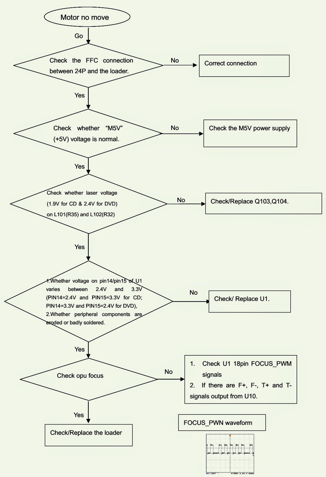
Spindle motor does not move; The power can not be on or off; All output voltages on the power board is 0V or deviated; Disc cannot be read.
SPINDLE MOTOR STOPPED.
POWER CANNOT BE TURN ON/OFF
NO INPUT VOLTAGE TO POWER BOARD
NO DISC DISPLAY

Blu-Link- URC FOR PLAYSTATION-3 - LEARNING AND TEACHING SET-UP PROCEDURE

$
0
0
LEARNING AND TEACHING METHOD
You can either start from a blank device or “learn” all the keys or you can start with a four-digit device code and customize it to meet your needs.
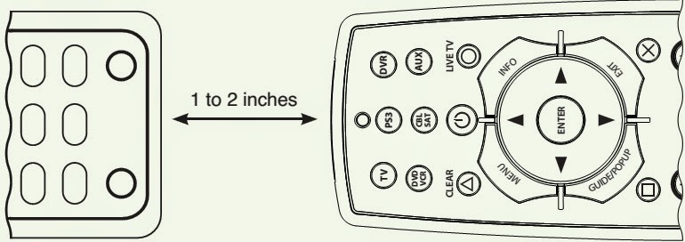
1: Line up Blu-Link with the remote you want to “learn” from, head to head about one to two inches apart on a solid surface.
Learning and Teaching Set-Up Method
2: Enter setup mode by holding the device button down for approximately 3 seconds. After 3 seconds all of the device buttons will blink to confirm that you are in setup mode.
3: Press [Rec] button to enter “learning” mode.  Note: You have 20 seconds to perform each of these steps. If you do not finish within 20 seconds, the device button light will turn off and setup mode will be exited. Learned keys will be retained but to learn additional keys you will need to reenter “learning” mode.
4: Press the key on Blu-Link that you wish to teach.  The device button will blink once to indicate it is ready to learn.
5: Press and hold the key on the other remote control you wish Blu-Link™ to learn. After about one second the device button will blink once to indicate successful learning or 4 times to indicate that it did not learn the key.
6: Repeat from step 4 until you have learned all of the keys you wish to teach. You can exit from learning either by waiting 20 seconds or by pressing another device key to exit.
* To achieve the best results during “learning” mode:
* If you are having trouble, move away from any Plasma TV, avoid fluorescent lighting and direct sunlight.
* Gradually vary the distance between the two remote controls.
* Some original remotes require you to tap the button to learn rather than holding it during learning.
* Learning only works on individual keys. Macros cannot be learned.
Remember, when programming keys such as arrow keys, the orientation between the remotes is reversed.
Forgetting Learned Keys
1: Enter setup mode by holding the device button down for 3 seconds. After 3 seconds all of the device buttons will blink to confirm that you are in setup mode.
2: Enter “forget” mode by pressing the Stop button. The device button will blink once to indicate it is ready to forget the keys it learned.
3: Press the key you wish to forget. If this key has learned anything, the device button will blink once and revert to its original settings, otherwise, it will blink four times in error.
4: Press keys you wish to forget until you are done. When you are done, you can either wait 10 seconds to time out or press another device button to exit.
Note: If you had previously entered a four-digit device code, the forgotten keys will return to their original settings.
Forgetting a Device
1: Enter setup mode by holding the device button down for 3 seconds. After 3 seconds all of the device buttons will blink to confirm that you are in setup mode.
2: Enter the code 9999 to erase the prior four-digit code and any learned keys for the device.  Note: Pressing any key besides “9” during this mode will exit.
Forgetting all Devices
1: Enter factory-reset mode by holding down two device buttons for 3 seconds. After 3 seconds all of the device buttons turn on to confirm you are in factory-reset mode.
2: Enter the code 9999 to erase the prior four-digit code and any learned keys for all devices.  Note: Pressing any key besides “9” during this mode will exit.
Controlling Volume (Punch Through)
  In a fairly typical setup with a TV, PS3 and Cable box, there is only one device that controls the sound. It would be difficult to switch devices between Cable and TV every time you want to change the volume. By default, Blu-Link is set so that regardless of what device you are using, when you change the volume, it is sent to the TV. This is called “punch through.” When you press any key on Blu-Link, the device button will light to show what device is receiving that command. For example, when you are watching a DVD and hit Pause, the DVD button will light. When you hit Mute, the TV button will light.
  Volume Punch Through is completely customizable. For example, if you have a surround sound system, you may want volume commands to be sent there instead of the TV. To do this, you would set the surround sound system as the sound master.
Setting Sound Master
  The sound master can be set for any device that supports volume up and volume down. To change from the default TV as master to another device:
1: Enter setup mode by holding the device button you wish to make master down for 3 seconds. After 3 seconds all of the device buttons will blink to confirm that you are in setup mode.
2: Press the Mute key and this device will now be the sound master. Future volume up, down, and mute operations for devices with punch through on will now control this device.
Advanced Configuration
  If you wish to independently control the volume without using punch through, punch through can be turned off (and back on) for any device. For example, if you have a surround sound system, you may wish to turn off punch through for the TV so you can still control its volume when the TV device button is selected.
Turning off Punch Through for a Device
  By default, all devices start with punch through turned on. For any device other than the PS3, punch through can be turned off.
1: To turn off punch through for a device, enter setup mode by holding the device button down for 3 seconds.   After 3 seconds all of the device buttons will blink to confirm that you are in setup mode.
2: Press the volume down (Vol -) key and that device will no longer punch through volume controls to the sound master.
Turning on Punch through for a Device
  If you accidentally turned punch through off for a device, it is simple to re-enable it.
1: To turn punch through back on for a device, enter setup mode by holding the device button down for 3 seconds.
3 seconds all of the device buttons will blink to confirm that you are in setup mode.
2: Press the volume up (Vol +) key and that device will now punch through to the sound master.

ACER X203H - MONITOR - SMPS SCHEMATIC (Power Supply Circuit Diagram)

$
0
0
SMPS SCHEMATIC(Click on the Schematic to Zoom In)

HOW TO REPLACE KEYBOARD TO HP Pavilion Widescreen Notebook zd7000

$
0
0
KEYBOARD REPLACEMENT
* Turn the notebook upside down
* Position the notebook so the front panel faces you.
* Remove the PM2.5x8.0 screw that secures the keyboard in the memory expansion/Mini PCI compartment.
* Remove the PM2.5x5.0 screw that secures the keyboard in the fan compartment.
* Turn the notebook right-side up with the front facing you.
* Open the computer.
* Use a flat bladed tool to pry forward on the four keyboard retaining tabs.  The tabs are located above the f1 and f2 keys, above the f6 and f7 keys, above the f11 and f12 keys, and above the end ‘end’ and ‘pg up’ keys.
* Lift up the back of the keyboard and swing it forward until it rests on the palm rest.
* Release the zero insertion force [ZIF] connector to which the keyboard cable is connected and disconnect the cable.
* Remove the keyboard. [Reverse the above procedure to install the keyboard]
KEYBOARD SPARE PART NUMBERS

POLOROID V23D – V27D –V30D LCD TV - Error Codes _TROUBLESHOOTING

$
0
0
NO PICTURE _ POOR PICTURE (Click on the pictures to Zoom In)

JBL DA-3504 - WIRING DIAGRAM - Amplifier Schematic - CAR AUDIO

$
0
0
WIRING DIAGRAM
 Note the wiring to both the Chassis Ground point and +ve of the battery. It is very important; that all these wires should be connected as same as shown; otherwise, audio distortion will occur when high volume is set. Similarly, all the wires to speakers should be twins, and never connect the ground point of all, assuming that all are ground.  Surely, it will damage the amplifier. High quality, thick copper wire [insulated] should be used for all wiring.   Monster cable is recommended to connect the speakers with amplifier.  Use only rated fuses installed.
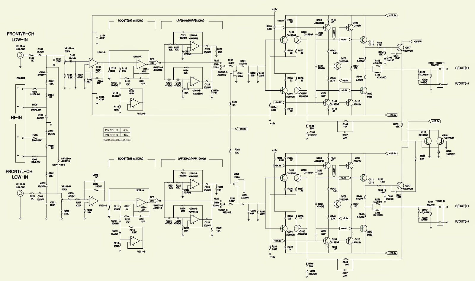
AMP SCHEMATIC
If needy, click on the pictures to Zoom In


CANON PRINTER LBP-1120 - ERROR MESSAGES

$
0
0
ERROR MESSAGES
Message List
  Status or error messages of the printer are displayed on a computer screen, as the printer is not equipped with a status display. This section will describe the messages, and their contents and procedures displayed on the computer screen.
Status Window
  CAPT displays the printing environment and printing status on the status window. On the status window, messages are indicated in the Message area depending on the following four conditions:
• Idling Status
• Printing Status
• Status Not Available
• Error Status
Also, the descriptions and procedures for the messages are displayed in the Error message area. For the details of the status window, refer to users guide.
1.Idling status
Indicates the printer contains no print jobs, and no problems for the printing operation.
The following three messages are indicated for the idling status:
Message area: Printer Ready
Error message area: None
Content: The printer is ready to print.
Message area: Printing Completed
Error message area: None
Content: The printer has completed the print job.
Message area: Printing Stopped
Error message area: None
Content: The printer has stopped the printing operation.
2.Printing status
Indicates the printer contains printing jobs and has no problems for the printing operation.
The following four messages are indicated for the printing status:
Message area: Printing
Error message area: None
Content: The printer is printing.
Message area: Printing Paused
Error message area: None
Content: The printer has stopped the printing operation and paused, because the Pause Job button is clicked during printing.
Message area: Stopping
Error message area: None
Content: The printer has stopped the printing operation, because the Delete Job button is clicked during printing.
Message area: Cleaning
Error message area: Now printing a cleaning page. Please wait a moment.
Content: The printer is printing a cleaning page.
3.Status Not Available
Indicates the printer information is not available.
The following three messages are indicated for the Status Not Available.
Message area: Status Not Available
Error message area: The printer is connected to a port of an unsupported type.
Content: The printer is connected as a local printer, and the port is not supported (FILE, LPT1.DOS, etc.).
Message area: Check Print Server
Error message area: The printer server is down or the server status window is not active.
Content: The printer is connected as a network printer, and the status window on the server side has not been started up.
Message area: Getting status
Error message area: Please wait a moment
Content: The printer has not received the port status, as the local port to which the printer is connected has just been switched from another printer.
4.Error status
Indicates errors have occurred on the printer.
When multiple errors occur, an error with the highest priority will be indicated first. When the first error is cleared, then an error with the second high priority will be indicated.
When an error occurs and then is cancelled in the middle of printing, the printer will resume printing on the ongoing page.
The following describes the messages for the Status Not Available. The messages are listed from the higher priority to lower priority.
Message area: Port Busy
Error message area: The port is being used by another device.
Content: The port is being used by another device.
Action: Check the port whether the correct printer is connected to it. If not, connect the correct printer to the port.
Message area: Check Printer/Cable
Error message area: Check the following. Is the printer switched on? Is the printer cable connected?
Content: The printer has become incommunicable during printing.
Action: Check the printer by following the instructions indicated in the Error message area, and perform the trouble shooting.
Message area: Incompatible Printer.
Error message area: The wrong printer is connected.
Content: The printer is not LBP-1120.
Action: When you use a printer other than LBP-1120, make sure to switch to the driver to which you are to connect.
 Message area: Clear Paper Jam
Error message area: 1. Open cover 2. Remove toner cartridge 3. Remove jammed paper
Content: A paper jam has occurred in the printer.
Action: Follow the instructions indicated in the Error message area.
Message area: Clear Paper Jam
Error message area: 4.Replace toner cartridge 5.Close cover
Content: A jam has occurred and then the cartridge cover has been opened.
Action: Follow the instructions indicated in the Error message area.
Message area: Close Printer Cover
Error message area: None
Content: The cartridge cover is open.
Action: Close the cartridge cover.
Message area: Check Toner Cartridge
Error message area: None
Content: The toner cartridge is not present in the printer. Or, the cartridge is not installed correctly.
Action: Set the cartridge correctly.
Message area: Change paper to xxx
Error message area: Change paper to xxx or force to print on yyy.
Content: The paper to be printed (yyy),recognized by the driver, differs from the specified paper (xxx).
Action: Switching the paper to xxx causes the printer to automatically resume printing. Or, clicking the Resume Job button causes the printer to resume printing with the present paper.
Message area: Add xxx Paper
Error message area: No paper loaded in printer
Content: Print paper is not set in the printer.
Action: Set print paper in the printer.
Message area: Printing Failed
Error message area: Data transfer to the printer was too late or a data transfer error occurred. Perform the following.
    1.  Discard last printed page. 2. Resume printing.
Content: Data transfer to the printer was too late. Or, the printer cable is disconnected or the port is connected to another printer during printing.
Action: If you follow the instructions indicated in the Error message area, the printer will print with lower resolution.
Message area: Insufficient Memory
Error message area: Quit all unnecessary applications running on the machine to which the printer is connected.
Content: The printer cannot obtain enough work memory for the language monitor.
Action: Follow the instructions indicated in the Error message area.
Message area: Service Error
Error message area: Printer Error. Contact the Shop the Printer Was Bought From.
Content: A service error has occurred in the printer engine.

LG HT-806 - NO HDMI PROBLEM - HOME THEATER SYSTEM

$
0
0
NO HDMI
Defect.Some caseswhere theHDMIOUTis not recognized byHDMI INTV.
Cause: Possible failurein the databaseof the MPEG;
Workaround: Upgrade the softwareas described below:
How to get intoInformation System:
* Enter SETUPmenuappears on the displayafterthe message"No Disc"
* In SETUP, go to "TV Aspect"andmove the cursor to[Highlight] option16:9.
* Pressbutton"to the right"using the remote control.
* Type 1_ 3_ 9_ 7_ 1_3_ 9_ENTER.
* Note the"Device Model"thatappearsNATV.
How to updateDVDprogram:
# Change thefilename todownload as"LG_ (model name) _(Version). ROM"[Case nameFile,possiblelyrics]".
# Save thefile to theroot folderof theblank CD.
# Insert theCDsetand the downloadwill beginautomatically.
# Rateofprogress of the updateis displayed, andthen the doorwill openwhen thedownloadis complete.
# Remove the disc.
# Disconnect thepower cord andplug it in andthenenter intosystem information.
& Disconnectpower, waita few momentsand reconnect
.

SAMSUNG GALAXY Star Pro – How to Sync: the Phone with PC - Kies software download and install

$
0
0

SAMSUNG "Kies" software download and install.
Connect to internet. (Do not connect your Phone via USB to PC, till the installation of the'Kies' is finished.)
  To synchronize Samsung Galaxy Pro smart phones, you have to download and install the “Kies” software from Samsung website.
If your computer’s operating system is “‘Windows-XP”, NET Framework 4 will be downloaded and installed automatically, when you try to install “kies” to yout PC.  It will take some time, to update this NET Framework, from Microsoft website, and be patient to complete it.  The time taken will depend on the PC environment.  After that, Hotfix and Windows media 11 will be downloaded, and installed.  Please stay with it to finish.
If your system’s O/S is Win-7 or later, there will be no update for NET Framework-4, and the ‘Kies” starts to install automatically.
You can access for 'Kies' download from Samsung website by these links too.
  The file is more than 71 MB; and might take some time to finish the download.  It will be best to save the file, rather than press Run.  After the download is over, press the ‘Kies’ icon at the downloaded location, to install the software.  It is a .exe file.  
  After successful installation, of ‘Kies”, a window will be opened before you, asking about whether you want to download and install the "Unified driver installer (USB) drivers."
  Check the box, and stay connected.  This  USB driver download cannot be saved anywhere; and it will be installed automatically after download.  Follow the instructions on screen.  Then the Codec pack.exe, will install device drivers, and finish the installation. 
  Restart the system.
'Kies" application icons will be at your desktop and can be started from there. Now the PC is ready to sync: with your Samsung Galaxy Star Pro.  Connect your phone via USB cable.  It will detect it automatically. 
  There is tutorial with this installed application to lead you more about how to work with it.

MARANTZ 1050 - SCHEMATIC - STEREO AMPLIFIER

$
0
0
SCHEMATIC (Circuit Diagram) - [Click on the schematic to Zoom in]

ST-15S1 - MARANTZ - SERVICE MODE - FACTORY MODE - SCHEMATIC [DAB/FM/AM Tuner]

$
0
0

FACTORY MODE / SERVICE MODE
FACTORY MODE
To reset all settings to default status, follow the procedure:
   1  Press the Power ON/OFF button to turn on the power.
   2   Press ‘Menu’ + ‘Band select’ buttons simultaneously and pull out mains cord.
   3  Mains cord pull in.
   4  During the initialization, it is converted to DAB Auto Tuning state.  [If step 3 doesn’t work, start over from step-1.  If the microprocessor has been initialized all the button settings are reset to default values; the values set upon shipment from the factory.
SERVICE MODE
Microprocessor version check.
1.       Connect the mains cord to the unit.
2.       Press the Power On/Off button while pressing the ‘Menu & Display’ button.
3.       All segments of the FLD will be light ON.
4.       Turn ‘Gyro Tuning’ dial.  Version is displayed on FLD.
5.       Turn the ‘Power Off’ to quit the Service mode.
SCHEMATIC (Click on the schematic to Zoom In)

SOFTWARE UPDATE-MARANTZ ST-15S1 - DAB/FM/AM Tuner

$
0
0
FIRMWARE [SOFTWARE] UPDATE _ MAIN MICROPROCESSOR
About replace the microprocessor with a new one.
[A]: Mask ROM (With software).  No need to write in of software to the microprocessor.
[B]: Flash ROM (With software).  Usually no need write in software.  But when the software was updated, you should write in of the new software to the microprocessor or flash ROM.  Please check the software version.
[C]: empty Flash ROM (Without software).  You should write in the software to the microprocessor or flash ROM. 
Update procedure [Writing main microprocessor procedure.]
IC300 [MB90F352PFM-G  ST-15S1 FOR N]
Necessary equipment
Windows PC [O/S: windows 2000 or Windows XP with  serial port.
RS-232C cable straight type [9 pin male – 9 pin female]
Connection JIG: ST-7001 DAB/MICOM UPGRADE BOARD [90M-ST7001JIG]
Writing software [flashprog 1 6lx-v01/11.exe]
Writng data [Marantz_DABxxxx.mhx].  Note: xx is version number
Install procedure.
Double click flashprog16lx-v01/11.exe
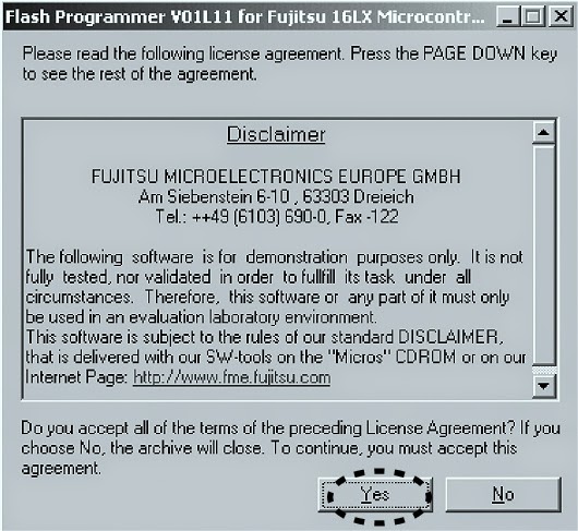
* Click "Yes"
* Click Next
* Check complete, and click next
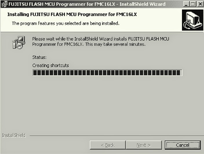
* Click install
* The status bar appears; click Next
Writing Procedure
* Disconnect the mains cord from the unit.
* Connect RS 232C on the connection JIG and Serial Port of windows PC with RS-232C cable.
* Turn the Mode Selector switch [SW401] of connection JIG to the MICOM UPGRADE side.
* Connect the connection JIG to SERVICE PORT in the rear panel of the unit.
* Connect the mains cord to the unit.
* Press the Power On/Off button, on the unit.  Launch up the FUJITSU Flash MCU programmer (FMC16LX)
* Click Start > Programs> FUJITSU FLASH MCU programmer & FMC16lx.
* Click 'Set Environment"
* Choose the using serial port and click OK.
* Choose MB90F352C/S/CS in Target Micro-controller.
* Select writing data and click Open.
* Click 'Full operation [D+E+B+P]
* Click OK.
* Close the FUJITSU MCU Programmer.
* Disconnect mains cord from the unit.
* Disconnect JIG from the unit.
* Check version [Refer to Service mode BY Previous Post Here]

HOW TO UPDATE DAB MICROPROCESSOR – MARANTZ ST-15S1 – DAB / FM / AM Tuner

$
0
0
DAB PROCESSOR UPDATE
Necessary Equipment
* Windows PC (OS: Windows2000 or Windows XP) with parallel port.
* Parallel cable straight type [25 pin male – 25 pin female]
* Connection JIG: ST-7001 DAB/MICOM UPGRADE BOARD (90M-ST7001JIG)
* Writing software and several files [DAB folder: include fast DRE310 Programmer.exe, install.bat, etc….]
* Writing data [Flash _DRE310_EVMSP | SLAVE_20050701_TBK_01_002_HE.bin]  File name will change according to release date.
Install procedure
Press right button of mouse on the install.bat, and choose the Edit in menu.
The text which copies ‘wdpnp.sys’ and ‘windrvr.sys’ file to the system folder of Windows is described.  Check the following texts.  When text is different, correct it, the save as filename. 
* Click X icon and close.
* Double click 'install.bat'
* Command prompt is launched, and files are copied.
* Check that the files have been copied.
* Press Enter or Space button, and command prompt closes automatically.
Writing procedure.
* Disconnect the mains cord from the unit.
* Connect parallel connector on the connection JIG and Parallel Port of windows PC with parallel cable.
* Turn the MODE SELECTOR switch [SW401] of the connection JIG to the DAB UPGRADE side.
* Connect the connection JIG to SERVICE PORT in the rear panel of the unit.
* Connect mains cord to the unit.
* Press the POWER ON/OFF button, and turn on the unit.
* Double click fast DRE310 programmer.exe
* DRE310| System Programmer is launched.
* The same as File Name of DataFlash is displayed.
* When a file name is different, change is required for the right file name.
* Check include this device in DataFlash.
* Choose Erase operation.
* Click execute.
* The data of DAB microprocessor is erased.  Erased Ok, appears in status.
* Choose Program and Verify in Operation.
* Click Execute.
* Writing data is written and verify.
* Click X icon, and close.
Press the Power On/Standby button, and turn off the unit.
Disconnect mains cord from the unit.
Disconnect connection JIG from the unit.
Check version.  Refer to Service Mode option; described by Previous Post Here.

SAMSUNG SGH-i900S - SOFTWARE UPGRADE PROCEDURE

$
0
0

SOFTWARE ADJUSTMENTS
There is 2set to download the binary image into your device.
First set.
1. JIG BOX (UMTS TEST JIG: GH80-03308A)
2. USB Cable: JIG to PC
3. Test Cable: JIG to SGH-i780 (GH39-00993A)
4. Power Cable: JIG to power supply
5. Serial Cable: SGH-i900to PC
6. Power Supply
7.  RF Cable(GH39-00599A): to Agilent8960or CMU200
8. Test Cable: JIG to SGH-i900 (GH39-00990A)
Second set
1. USB DATA Link Cable: GH39-00922A
2. Battery: GH43-03110A
Software Download
Equipment for Software Download.
Pre-requisite for Download
▶ Downloader Program - [Image Version].exe
▶ USB Driver - PDA: Samsung MITs USB Sync[Samsung MITs USB Sync.zip] - Phone: Samsung CDMA Modem[Samsung CDMA Modem.zip]
▶ SGH-i900 Mobile Device
▶ Driver Installation.
Driver Installation (PDA)
▶Make sure that you install drivers.
▶If you installed the latest ActiveSync program, you don’t need to install the pda driver. Please install the latest ActiveSync program.
Driver Installation (Phone)
When you download the phone image, youneed the driver of Samsung CDMA Modem.
If you want to download the phone image, install the Samsung CDMA Modem driver.
After you install the driver of Samsung CDMA Modem, please restart host computer.
Execute the Downloader Program. [Image Version.exe]
Turn off your device.
Connect your device to a host computer by using USB DATA Link Cable.
Turn on your device and wait until' START' button is activated.
If "START" button is not activated, terminate the application and reconnect USB data link cable and retry.
Please click “START” button.
When the download is finished, the phone is rebooted automatically.
Download Procedure
Job Done

Trouble Shooting
“PDA Device not found” message.
Make sure that your device is connected a host computer by USB DATA Link cable.
After you install“ phone USB driver(Samsung CDMA Modem)”at first time, you may see “Port open failed…”message or application hang while downloading a phone image. If so, terminate the application and then try the download again.
If USB port is changed, at first time you may see “Port open failed…”message or application hang. If so, terminate the application and then try the download again.
If USB cable to the mobile device is not connected tightly, you may see “Port open failed…”message or application hang. If so, terminate the application and then try the download again.
If you always see“ port open failed” message or application hang,
1. When failed application is activated, go to the device manager, remove the SAMSUNG CDMA Modem and SAMSUNG USB Composite Device.
2. Rename C:\WINDOWS\system32\drivers\Modem.sys to other name.(ex. Mod em-.sys)
3. Go to control panel->program add/remove, and then remove Samsung CDMA Modem driver or Samsung USB driver(MCCI)
4. Restart your PC.
5. Install attached SAMSUNG CDMA Modem_4.34
Try the download again.
“Write Failed” message
If battery level is low, use charged battery and try again.
How to deal with an error in the computer USB port of the computer.
Symptom: Device is not identified after connecting it.
Cause: The device is connected before the previous connection is complete. All devices should be connected one by one. Otherwise, an error may occur in the computer USB port of the computer.
Solution:
Proceed with the following action in order only when the previous action does not work.
1) Unplug the USB port from the computer and plug it again.
2) Open the Device Manager and remove the USB hub and install it again.
3) Reboot the computer.

HOW TO DISASSEMBLE SAMSUNG Omnia SGH i900 GSM Phone

$
0
0
DISASSEMBLE PROCEDURE
* UNSCREW 4 REAR Points.
* Separate the REAR cover 1. Separate the rear case using a disassemble tool following indicated direction.
* Separate the REAR cover-2.   Separate the REAR using a disassemble tool following indicated direction.
* Lift the REAR from the FRONT Ass`y.   Separate the REAR from the FRONT Ass`y with care.
* UNSCREW PBA 2 Points.
* Separate GPS CONNECTOR.   Separate GPS Connector from the PBA Connector with great care. (Be careful not to damage FPCB & nearby chipsets.)
* Separate Main FPCB CONNECTOR.  Separate Main FPCB Connector from the PBA Connector with great care. (Be careful not to damage FPCB & nearby chipsets.)
* Separate LCD FPCB CONNECTOR.   Separate LCD FPCB Connector from the PBA Connector with great care. (Be careful not to damage FPCB & nearby chipsets.)


* Separate VOLUME KEY FPCB.  Separate Volume Key from PBA. (Be careful not to damage 
 VOLUME KEY FPCB)
* Separate TSP FPCB.  Separate TSP FPCB from PBA not to tear FPCB with great care.
* Separate OJ (Optical Joystick) KEY FPCB.  Separate OJ KEY with great care not to tear OJKEY FPCB.
* Remove Bracket Sheet.  Remove Bracket sheet with great care not to damage GPS wire & MAIN FPCB.
* Separate SPK Bracket. Lift SPK Bracket from FRONT Ass`y.
* UNSCREW FRONT 2 Points.
* Separate FRONT.  Separate FRONT from FRONT Ass`y following indicated direction.
* Separate Key Pad.  Separate Key Pad from FRONT Ass`y.
* Separate OJ (Optical Joystic) KEY FPCB. Separate FPCB from FRONT Ass`y using guide hole.
* Separate TSP Module.  Separate TSP Module from PBA with care.
* Separate LCD from TSP.  Separate LCD from TSP with great care not to damage TSP.
Reverse the processes to re-assemble.

SGH 480F - FIRMWARE ADJUSTMENTS - SAMSUNG GSM MOBILE PHONE

$
0
0
FIRMWARE UPDATE PROCEDURE
1. JIG (GH80-03308A): Download, Trace, Calibration, etc
2. RF test cable (GH39-00397A): RF test
3. Test cable (GH39-00886A): JIG to phone
4. Travel Adaptor (GH44-01702A)
5. Data Link Cable (GH39-00922A): USB cable
6. Serial cable (LJ39-00013A) : PC to JIG
7. Test cable (GH39-00890A): JIG to phone
Software Downloading
Downloading Binary Files
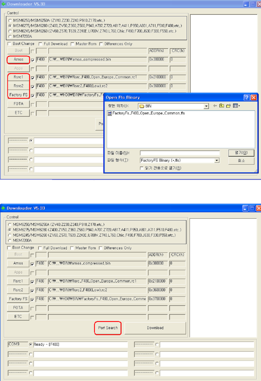
Four binary files for downloading F480
amss_compressed : Modem binary for communication function & user interface and various applications.
Rsrc_F480_Open_Europe_Common.rc1: Files need for each application
Rsrc2_F480(Low).rc2 : Power on/off animation
FactoryFs_F480_Open_Europe_Common.ffs : Default file system to be put into in initial production.
Pre-requisite for Downloading
• Downloader Program (MultiLoader V5.33)
• SGH-F480 Mobile Phone
• USB Data Link Cable
• Binary files.
S/W Downloader Program
1.Boot the F480 by pressing' power ON key'+'Camera key + Side up key'at the same time.  If you do properly, you can see the following message on Main LCD.
" DEMSBL BOOT Loader for MSM6280 Downloader Ver 5.33
2. Load the binary download program by executing the "MultiLoader V5.33.exe".  And Check theMSM6275/MSM6280.
3.Select the binary file what you want to download.  Up to eight ports are supported.
4. Press the button 'Port search'.
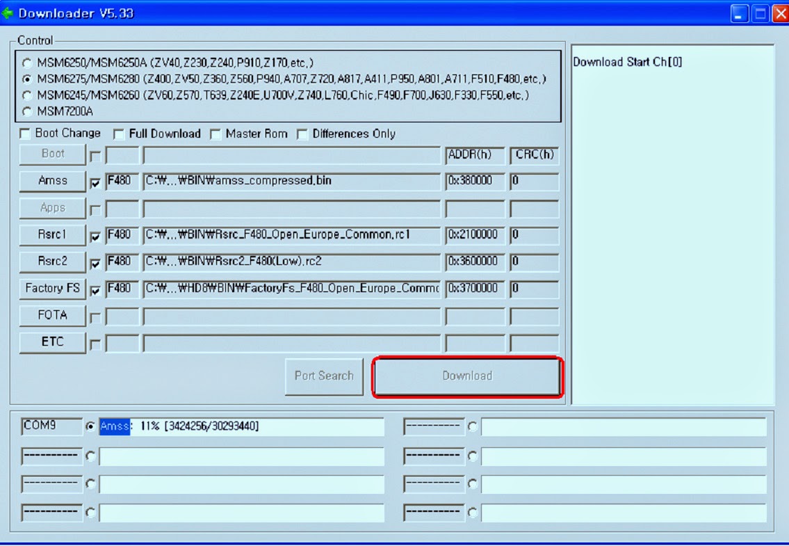
5.Now press the button ' Download'.
6.When downloading is complete, UE reboot automatically.  If there is difference in FactoryFS.bin, UE will format file system automatically.

HOW TO DISASSEMBLE SGH-480F - SAMSUNG GSM MOBILE PHONE

$
0
0
DISASSEMBLE
Unscrew the REAR at the four points.
Disassemble the IF cover and SD card cover.
Disassemble the Rear from the bottom side to the upper side.
Disassemble the touch-key connector, antenna cable, SPK connector, camera connector.
Unscrew the screw.
Disassemble the PBA from the FRONT ASS'Y
Remove the antenna and antenna cable.
Remove the SPK ass'y and camera
Remove the screw
Disassemble the touch key FPCB
Remove the bracket.

HOW TO DISASSEMBLE NOKIA 6310 - MOBLILE PHONE

$
0
0

DISASSEMBLE PROCEDURE
To open the unit, four T6 screws have to be unscrewed. Do not use the torque driver for this, because torque drivers are mostly designed for fastening and not for unscrewing the screws.
Hold the unit with the volume key against the table.  Hold the A-Cover with your left hand and then grab the B-Cover to unlock the side snaps in the bottom area.
Before loosening the upper snaps of the cover, be sure that you press the module against the A-Cover.  The module is still fixed with the A-Cover with one hidden screw in the antenna area.
There are three clips, which have to be released.  Be careful when pulling the covers apart in the antenna area.  It is easier if you wobble the covers carefully against each other.
Now you can take away the B-Cover.  Be careful not to damage the antenna, which can break if you try to rotate the cover against each other.
See the screw, which fixes the antenna and holds the module inside the A-Cover.
Do not touch the antenna with your fingers.  The fingertips would cause corrosion to this sensitive material.
Lifting up the CMT module is very easy now.  Protect the display with a foil.
Four clear plastic clips hold the UI module on the CMT module.  Unlock these clips when you need to remove the UI module.
Never touch the pads with your finger to avoid corrosion.
If you want to remove the speaker or buzzer, do not grab the items at the spring contacts.

Viewing all 2033 articles
Browse latest View live


<script src="https://jsc.adskeeper.com/r/s/rssing.com.1596347.js" async> </script>