↧
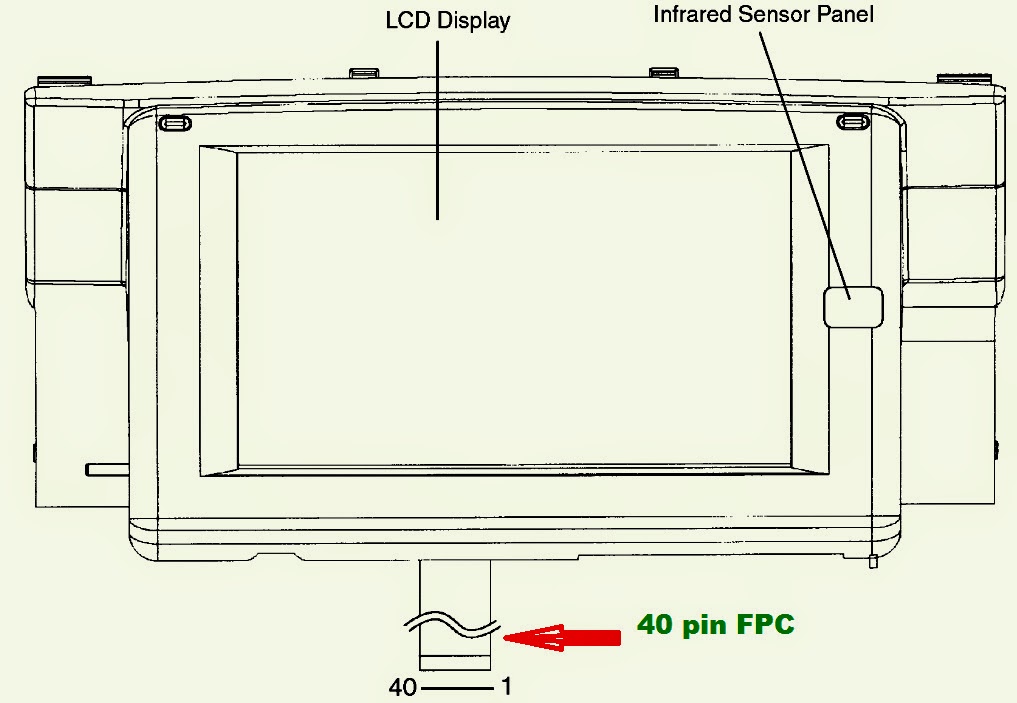
PANASONIC CN-TM4491A-7 Inch Color LCD unit – Connection Details-[MAZDA – [Atenza]
↧
ACER ASPIRE 9300 – 7000 – TravelMate 7510 - TROUBLESHOOTING
SYSTEM CHECK PROCEDURE
External Diskette Drive Check
Do the following procedures to isolate the possible effects from a controller, driver, or diskette. A writable, diagnostic diskette is required. NOTE: Make sure that the diskette does not have more than one label attached. Multiple labels may cause damage to the drive or make the drive fail.
1. Boot from the diagnostic diskette and start the diagnostic programs.
2. See if FDD test is passed as the programs run the FDD test.
3. Follow the instructions in the message window. If errors occur with the internal diskette drive, reconnect the diskette connector on the system board. If the errors still remain:
1. Reconnect the external diskette drive.
2. Replace the external diskette driver.
3. Replace the main board.External CD-ROM Drive Check
Do the following procedures to isolate the possible effects from a controller, driver, or CD-ROM. NOTE: Make sure that the CD-ROM does not have any label attached. The label may cause damage to the drive or make the drive fail.
1. Boot from the diagnostic diskette and start the diagnostic programs.
2. See if CD-ROM test is passed when the programs run the CD-ROM test.
3. Follow the instructions in the message window. If errors occur, reconnect the connector on the system board. If the errors still remain:
1. Reconnect the external CD-ROM drive.
2. Replace the external CD-ROM drive.
3. Replace the main board.Keyboard or Auxiliary Input Device Check
Remove the external keyboard if the internal keyboard is under test. If the internal keyboard does not work or an unexpected error appears, make sure that the flexible cable extending from the internal keyboard is correctly connected on the system board. If the keyboard is correctly connected, run the Keyboard test. If errors occur, do the following procedures in sequence to correct the problems. Do not replace a non-defective FRU.
1. Reconnect the keyboard cable.
2. Replace the keyboard.
3. Replace the main board.
The following auxiliary input devices are supported by this computer.
* Numeric keypad
* External keyboard.
If any of these devices do not function, reconnect the cable and repeat the anterior procedures.
Memory Check
Follow the procedures below to correct the memory errors.
1. Boot from the diagnostic diskette and start the diagnostic programs.
2. Go to the diagnostic memory in the test items.
3. Press F2 in the test items.
4. Follow the instructions in the message window. NOTE: Make sure that the DIMM is correctly inserted into the connector. A wrong connection will cause errors.
Power System Check
To verify the symptoms, power on the computer by using the following power sources separately.
1. Remove the battery pack.
2. Connect the power adapter and check the power supply.
3. Disconnect the power adapter and install the battery pack, then check the power supply.
Check the Power Adapter
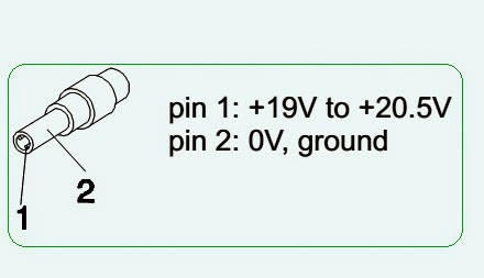
Unplug the power adapter cable from the computer and measure the output voltage at the plug of the power adapter cable. See the illustration and follow the procedures below.
1. If the voltage is not correct, replace the power adapter.
2. If the voltage is within the range:
(1) Replace the system board.
(2) If the problem is still not resolved, see “Undetermined Problems”.
(3) If the voltage is not correct, go to the next step. NOTE: An audible noise from the power adapter does not always indicate a defect.
3. If the power-on indicator does not light up, check the power cord of the power adapter for continuity and correct installation.
4. If the operational charge does not work, see “Check the Battery Pack”.
Check the Battery Pack
Follow the procedures below to check the battery pack. From software, this helps to identify the problem is on recharging or discharging.
1. Check the Power Management in Control Panel.
2. Then confirm that the parameters shown in the screen for Current Power Source and Total Battery Power Remaining are correct.
3. Repeat the step 1 and step 2 for both battery and adapter. From hardware, this helps to identify whether you should replace the battery pack or not.
1. Power off the system.
2. Remove the battery pack and measure the voltage between terminals one (+) and seven (-). There are seven terminals totally. See the illustration below.
3. If the voltage is still less than 7.5V after recharging, replace the battery. If the battery status indicator does not light up, remove the battery pack. After the battery pack returns to room temperature, re-install it to the system. If the charge indicator does not light up, replace the battery pack. If the charge indicator still does not light up, replace the AC/DC charger board.
Touch-pad Check
If the touch-pad does not work, follow the procedures one at a time to correct the problem. Do not replace a non-defective FRU.
1. After rebooting, run Tracking Pad PS2 Mode Driver. For example, run Syn touch driver.
2. Run utility with the PS/2 mouse function and check if the mouse is working.
3. If the PS/2 mouse does not work, then click if the main board to switch board FPC is connected properly.
4. If the main board to switch board FPC is connected correctly, then check if the FFC on the touch pad PCB is connected properly.
5. If the FFC on the touch pad PCB is connected correctly, check if LS851 JP1 Pin6 = 5V are pulse. If yes, then replace switch board. If not, then go to the next step.
6. Replace the touch pad PCB.
7. If the touch pad still does not work, then replace the FPC on Track Pad PCB. After you use the touch-pad, the pointer drifts on the screen for a short time. This self-acting pointer movement will occur when a slight, steady pressure is applied to the touch-pad pointer. This symptom is not a hardware problem. No actions are necessary to be taken if the pointer movement stops in a short period of time.
↧
↧
ERROR CODES AND BIOS BEEP CODES - ACER ASPIRE 7000 - ASPIRE 9300
Phoenix BIOS beep codes & Error codes _ Acer Aspire
Power On Self Test [POST] _ Error Message
Power On Self Test [POST] _ Error Message
The POST error message index lists the error message and their possible causes.
NOTE: Perform the FRU replacement or actions in the sequence shown in Error Message List, if the FRU replacement does not solve the problem, put the original part back in the computer. Do not replace a non-defective FRU.
The error messages are listed to indicate the BIOS signals on the screen and the error symptoms classified by functions. If the symptom is not included on the list, please refer to “Undetermined Problems”.
NOTE: Most of the error messages occur during POST. Some of them show information about a hardware device, for example, the size of memory installed. Others may indicate problems with a device, such as the way it has been configured.
NOTE: If the system fails after you make changes in the BIOS Setup Utility menus, please reset the computer. Enter Setup and install Setup defaults to correct the errors.
Index of Error Messages: Error Message List
System CMOS checksum bad - Default configuration used :: RTC battery. Run BIOS Setup Utility to reconfigure system, and then reboot system.
Real time clock error :: RTC battery. Run BIOS Setup Utility to reconfigure system time, and then reboot system. Main board.
Previous boot incomplete - Default configuration used :: “Load Default Settings” in BIOS Setup Utility. RTC battery. Main board.
Invalid System Configuration Data:: “Load Default Settings” in BIOS Setup Utility. Main board.
Operating system not found :: Enter Setup and see if fixed disk and drive A are properly identified.
Diskette drive, Hard disk drive, Main board.
Power-on indicator turns off and LCD is blank. :: Power source (battery pack and power adapter.)“Power System Check“.
Ensure every connector is connected tightly and correctly.
Reconnect the DIMM.
Main board.
Power-on indicator turns on and LCD is blank.
Power source (battery pack and power adapter.)
Reconnect the LCD connector
Hard disk drive
LCD cable
LCD inverter
LCD
Main board.
Power-on indicator turns on and LCD is blank. But you can see POST on an external CRT.
Reconnect the LCD connectors.
LCD cable
LCD inverter
LCD
Main board.
Power-on indicator turns on and a blinking cursor shown on LCD during POST.
Ensure every connector is connected tightly and correctly.
Main board.
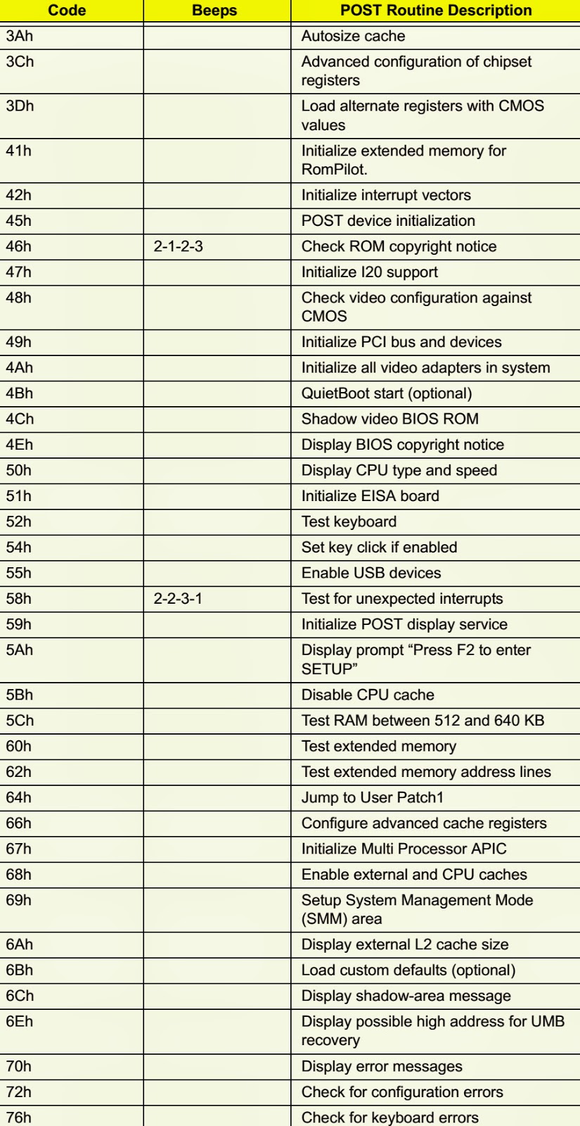
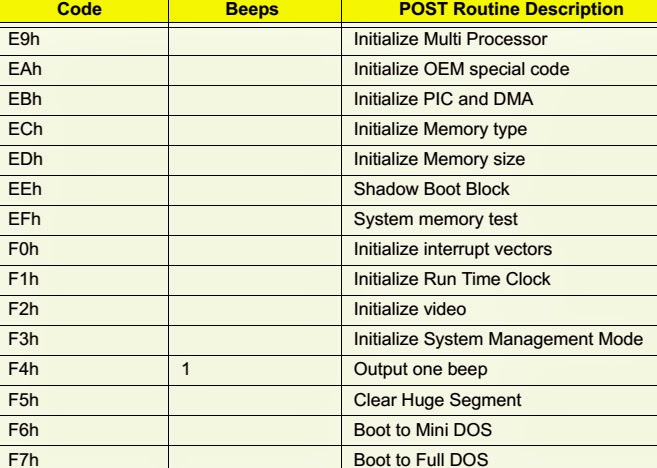
Phoenix BIOS Beep Codes.
CLICK ON THE PICTURES TO MAGNIFY
↧
HOW TO BYPASS PASSWORD - KEYBOARD REMOVAL - ACER ASPIRE
REMOVE KEYBOARD – ACER ASPIRE 7000 – 9300 – 7510 TravelMate _
Password Bypassing & BIOS Recovery
For RD and CSD to debug easily, AS7000/9300 &TM7510provides one hardware PIN pad for bypassing Password Check, and one Hotkey to enable BIOS Recovery.
1. PIN pad: To short PIN pad to bypass password check.
2. Hotkey to enable BIOS Recovery: Fn+ESC, then Power Button, AC+DC coexistence is strongly recommended.
Bypassing Password Check :: If the user has set Password ( power-on or setup password) for security reason, BIOS will check password during POST or when entering the BIOS setup menu. However, if it is necessary to ignore the password check, the user may enable short PIN Pad to bypass password check.
BIOS Recovery :: Boot Block is a special block of BIOS. It is used to boot up the system with minimum BIOS initialization. The user can enable this feature to restore the BIOS to a successful one if previous BIOS flashing process fails.
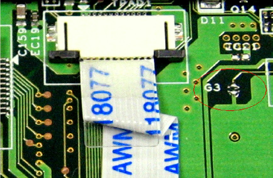
PIN pad Location :: AS7000/9300 & TM7510 provides one hardware Pin pad under the keyboard. RD/CSD can enable this function by shorting this pad. The Pin Pad location should look as the figure.
PIN Pad :: Bypassing Password Check, Keep shorting G3 (2 triangle pad) as above PIN pad and then powering on the system will force the BIOS to clear Supervisor and User passwords. That means both the power-on and setup passwords are all cleared.
HDD password clean: It uses on DOS environment. To decode HDD password error code for unlock hard disk.
A\> unlock6 XXXX 00
XXXX -HDD password error code
Unlock6.exe v1.1 2 May 2003
Choice what kind of the password to be generated:
0) Exit
1) Scan code
2) Upper case ASCII Code
3) Lower case ASCII Code
Enter your choice 2 <- chose 2
XXXXXX
XXXXXX
XXXXXX
Those passwords are master password.
Restore BIOS by the Crisis Disk
Enter this function by Fn+ESC, and Power Button. To use this function, it is strongly recommended to have the coexistence of AC and Batter powers. If this function is enabled, the system will force the BIOS to enter a special BIOS block, called Bootblock. RD/CSD can use this special BIOS code to recover the BIOS to a successful one if previous BIOS flashing process fails. However, before doing this, one Crisis Disk should be prepared in WinXP. Detailed steps are as the followings,
1 Prepare the Crisis Disk in WinXP (Crisis Disk will be released when BIOS V1.00 is released)
2 Insert the Crisis Disk to a USB floppy drive which is attached to the failed machine.
3 On the power-off state, press Fn+ESC and press button. The system should be powered on with Crisis Recovery process.
4 BootBlock BIOS starts to restore the failed BIOS code. Short beeps should be heard when flashing.
5 If the flashing process is finished, a long beep should be heard.
# Power down the system when Step 3.5 is finished.
If the crisis recovery process is finished, the system should be powered on with successful BIOS.
RD/CSD can then update the BIOS to a workable on by regular BIOS flashing process.
Intermittent Problems
Intermittent system hang problems can be caused by a variety of reasons that have nothing to do with a hardware defect, such as cosmic radiation, electrostatic discharge, or software errors. FRU replacement should be considered only when a recurring problem exists. When analyzing an intermittent problems, follow the procedures below
1. Run the advanced diagnostic test for the system board in loop mode at least 10 times.
2. If no error is detected, do not replace any FRU.
3. If any error is detected, replace the FRU. Rerun the test to verify that there are no more errors.
Removing the Keyboard
1. Open the notebook as shown.
2. Remove the middle cover. Though it is combined tightly, detach it from the main unit carefully. Do not pull it abruptly.
3. There are four latches securing the keyboard.
4. Push those latches by the screw driver as shown and the keyboard will pop up a little.
5. Remove the keyboard and reverse it.
6. Carefully pull the keyboard FFC lock, and then disconnect the keyboard FFC.
↧
COMPAQ PRESARIO 1800 - 1800T SERIES - HOW TO CLEAR POWER-ON PASSWORD
Presario 1800/1800T Series (Models: XL280, XL380, XL381, and XL390) Keyboard Removal
PASSWORD RESET
PASSWORD RESET
If you do not know the Power-on password, clear it by performing the following steps:
1. Turn off the Notebook.
2. Disconnect the power cord.
3. Remove the battery.
4. Remove the Palm rest cover.
5. Remove the keyboard.
6. Remove the heat sink.
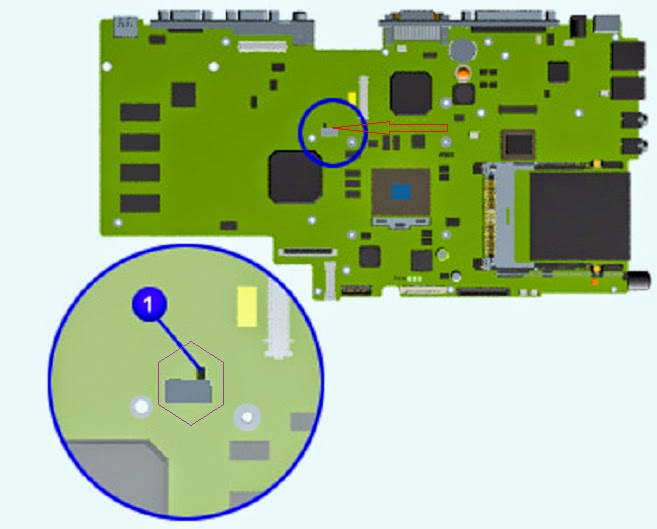
7. Locate the CMOS switch to the right of the CD/DVD drive on the system board.
8. Slide the black switch to the right {1} holding it in this position for at least 15 seconds to ensure that the password is cleared.
Reassemble the Notebook.
Turn on the Notebook to verify that the Power-on password has been cleared. If it has not been cleared, repeat this procedure.KEYBOARD REMOVAL
Palm rest Cover with Touch-pad
It is not necessary to remove the display panel assembly to access the interior components of the Notebook.
To remove the Palm rest cover with Touch pad, complete the following steps:
1. Prepare the Notebook for dis-assembly.
2. Close the display and turn the Notebook upside down.
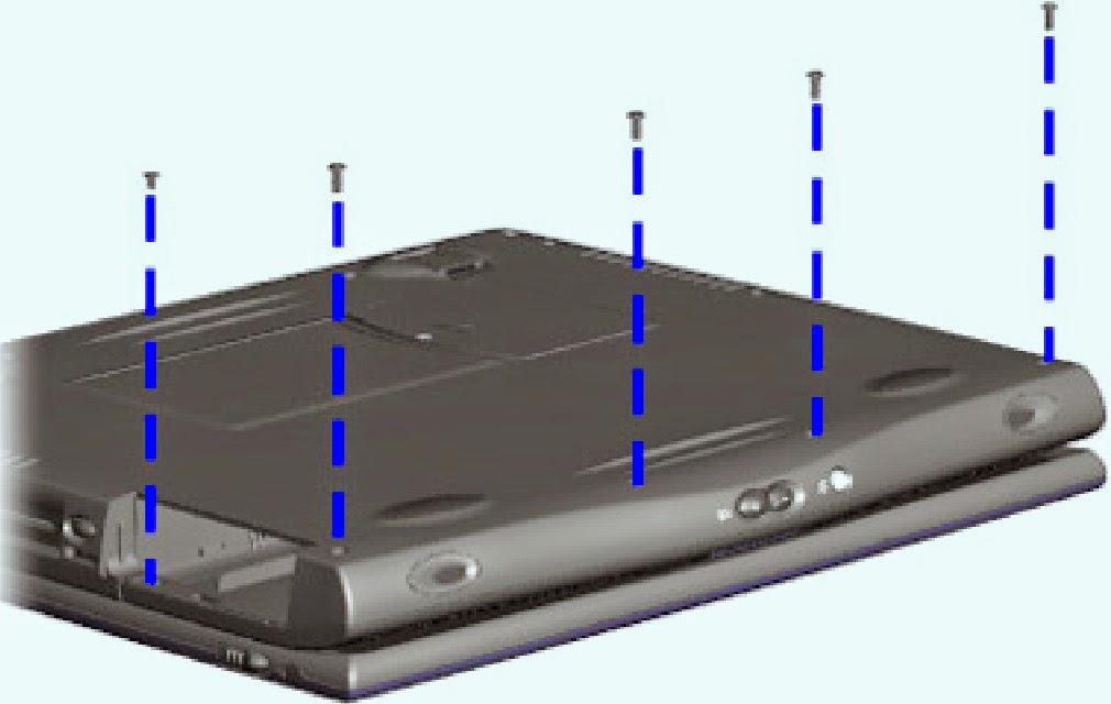
3. Remove four screws from the bottom of the Notebook, and one from the battery compartment.
4. Turn the Notebook right side up and open the display.
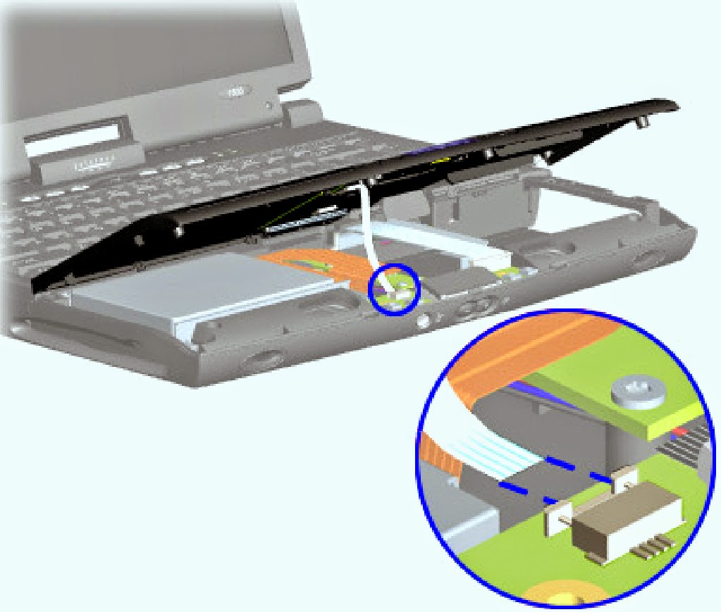
5. Lift up the front end of the Palm rest cover. Note: It may be necessary to apply pressure on the sides of the Palm rest cover to release it from the chassis.
6. Disconnect the flex cable from the ZIF [Zero Insertion Force] Connection the Display module.
Gently lift the front of the keyboard, disconnect the flex cable from the ZIF Connector on the system board, and remove the keyboard.
↧
↧
SAMSUNG GALAXY ALL MODELS - HOW TO UNLOCK [Reset] SAMSUNG BY UNLOCK CODE
UNLOCK SAMSUNG GALAXY BY UNLOCK CODE
Unlock Samsung Galaxy Star Pro Duos with this user-friendly service will give you Samsung Galaxy Star Pro Duos unlock codes that you can enter on your phone’s keypad. Our popular, easy to use and quick service will provide you with your Samsung Galaxy Star Pro Duos unlock code.
Using the Galaxy Star Pro Duos unlock codes will remove the SIM Network Unlock PIN or Enter Network Lock Control Key message and enable you to use your Galaxy Star Pro Duos phone with other networks.
Carriers from all around the world are supported including; AT&T, T-Mobile, Rogers, Fido, Bell, Telus, Vodafone, Orange and many more. The only exceptions are: NET10, Softbank, Sprint, Straight Talk, TracFone and Verizon.
Galaxy Star Pro Duos region unlock – Along with the network unlock code this service will provide the unfreeze code to disable the Samsung Galaxy Star Pro Duos region lock.It is recommendedperforming check of your Galaxy Star Pro Duos phone history. If your phone is blacklisted you will be unable to use the phone on some mobile networks. Make sure your Galaxy Star Pro Duos phone is not blacklisted prior purchase or unlocking.Samsung Galaxy Star Pro Duos serial number (IMEI) will be checked against 50 billion records from 18,000+ law enforcement agencies inc. FBI and network operators from 30+ countries worldwide.Blacklist IMEI Check Report This service will provide you with online verifiable background history report of any Samsung Galaxy Star Pro Duos to make sure that your Galaxy Star Pro Duos phone is not been recorded as lost & stolen, blacklisted or has insurance claims made against it.You can had this report by this site: Samsung Galaxy Unlock
If your phone is hard locked, unlock codes will not work.To tell if your phone is hard locked power on the phone with a SIM card from a different network.Hard locked phones will display the message Network lock with a Dismiss or SOS button. There will be no place to enter an unlock code.
How to know if the phone is network locked
* Insert a SIM card from a different network and power on your phone.
* If the phone is network locked, it will display one of the following messages:
* SIM network unlock PIN
* Network lock.
* Phone freeze SIM unavailable. Contact your service provider
* SP lock
* If the phone is network locked, it will display one of the following messages:
* SIM network unlock PIN
* Network lock.
* Phone freeze SIM unavailable. Contact your service provider
* SP lock
* SIM password
** If you get a different message and you are not sure if your phone is network locked, do not order unlock codes.
** If you get a different message and you are not sure if your phone is network locked, do not order unlock codes.
How to purchase an unlocking service on FastGSM?
* Go to the detail page for your phone on FastG SM.
* Select a service.
* Click Buy Now and follow the instructions. You will be asked to create an account or sign into your existing account.
* For unlock codes, make sure to select Samsung Unlock Codes with the correct region where the phone is currently network locked (i.e.,EUROPE).
* Find your phone’s unique IMEI (identification number).To find the IMEI number, power on the phone without a SIM card and type *#06# on the keypad.
* The phone will display the IMEI number.
* Submit your IMEI to the FastGSM website. Enter the number without spaces or slashes. Your IMEI is only the first 15 digits.
Wait to receive your phone’s unique unlock code(s) by email.
SIM network unlock PIN / Enter Network Lock Control Key screen.
Have the unlock code. How to unlock the phone.
* Type your unique Network unlock code (NCK).
* Click Unlock.
* If you get a message saying Unsuccessful, it means there have been too many failed attempts to enter the unlock code.
* If this happens, full reset your phone by typing *2767*3855# and wait until the phone has restarted (all data will be erased).
* Type your unique Unfreeze code (MCK) into the SIMnetwork unlock PIN screen.
*You will get another message saying Unsuccessful, but don’t worry_this is fine.
* Now type your unique Network unlock code (NCK) and click Unlock.
NETWORK LOCK SCREEN
At this point you should be prompted for your Network unlock code (NCK).
Type the code and the phone will be unlocked.
INVALID sim CARD SCREEN
Type the following. Replace Network [NCK] with your actual code: #0111*Network (NCK)#
PHONE FREEZE SCREEN
If you get the Phone freeze message, it means there have been too many failed attempts to enter the unlock code. However, you can still unlock the phone using the Unfreeze code (MCK). If your phone has a physical keypad, type the Unfreeze code (MCK) into the Phone freeze screen. Nothing will show up_this is fine. If nothing happens,you can try hitting # or the Call key after entering the code. If your phone has only a touch screen, tap Call on the Phone freeze screen and then enter your Unfreeze code (MCK). Once phone freeze is disabled, Network lock or SP lock screen will appear. Follow the directions for Network lock or SP lock to unlock your phone.
PHONE LOCKED; RETURN FOR SERVICE SCREEN
Type the following.
Replace Unfreeze(MCK) with your actual code:#0199*Unfreeze (MCK)#
SP LOCK SCREEN
At this point you should be prompted for your SPCK code.
Type the code and the phone will be unlocked.
SIM PASSWORD SCREEN
Enter your Unfreeze code (MCK) at the prompt.
SIM LOCK - ENTER PASSWORD SCREEN
Type the following. Replace Unfreeze (MCK) with your actual code: #0149*Unfreeze (MCK)#NETWORK UNLOCK PIN IS ENTERED IN CORRECTLY. CONTACT YOUR SERVICE PROVIDER SCREEN
* Power on the phone without SIM card.
* Dial #7465625638#
* Type your unique Unfreeze code (MCK)
* You will get another message saying Unsuccessful, but don’t worry_this is fine. Now type your unique Network unlock code (NCK)
↧
AOC 19 Inch LCD MONITOR – 193FW - MAIN POWER AND BACK-LIGHT INVERTER SCHEMATIC
↧
HOW TO RESET Dell Precision T3500 (Desktop Computer)
RESET PROCEDURE
The computer’s system board offers two jumpers—a password enables jumper and a RTCRST (Real Time Clock Reset) jumper.
Password Enable Jumper
PSWD -Password enable. The system password will be cleared and disabled when the system is started with this jumper removed.
Pins 1-2 shorted enables password.
NVRAM Reset Jumper
RTCRST -Clears NVRAM. The NVRAM will be cleared when the jumper is closed (use the jumper from the password bridge). To properly clear; AC power must
be applied (not necessarily turned on) to the system for about 10 seconds while the jumper is closed.
Pins 1-2 shorted clear NVRAM
The picture below shows the location of the configuration jumpers on the system board.
NOTE: You can use the RTCRST jumper procedure above to attempt recovery from a No POST, No Video situation.↧
HOW TO OPEN Dell Precision T3500 Desk-Top Computer
TO OPEN THE COVER
Pull the cover release latch toward the back of the computer.
Pivot the cover away from the computer and then remove the cover.Removing the Battery.
The memory module shroud has been removed to increase visibility to the following procedure.
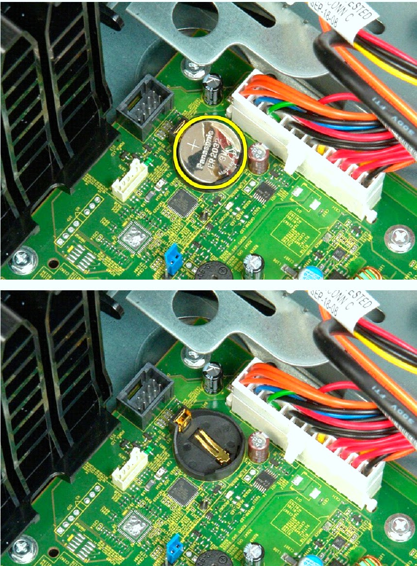
Use a small screw driver or a scribe to push the coin-cell release tab.
Remove the coin-cell battery from the computer.
↧
↧
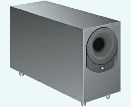
JBL BASS15 _ JBL BASS16 - SCHEMATIC DIAGRAM _ Powered Sub-Woofer
↧
BP600.1 - JBL - SCHEMATIC [CIRCUIT DIAGRAM] - Wiring Diagram - CAR AUDIO
↧
DENON CDR-W1500 CD RECORDER – HOW TO OPEN
HOW TO OPEN DENON CDR-W1500 CD RECORDER
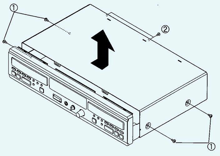
TOP COVERRemove 4 screws (1) on both sides.
Remove 2 screws (2) on rear side.
Detach the top cover to the arrow direction.Front panel
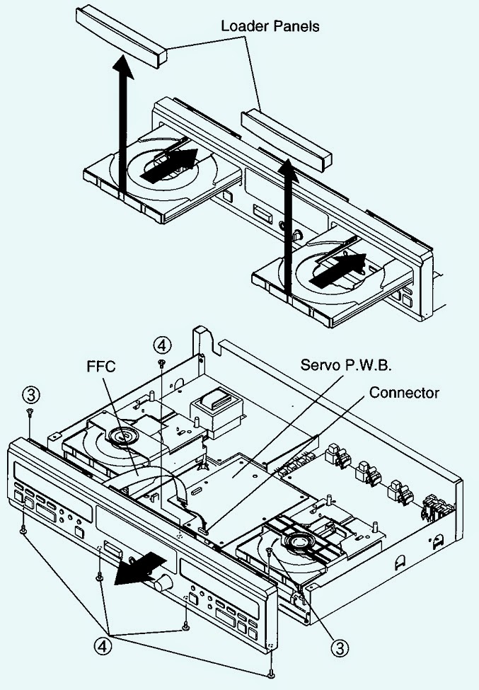
Turn the unit Power ON, and open both trays of the CD mechanism and CDR mechanism.
Remove the loader panels and switch off the power after closing the trays. Disconnect the power plug.
Disconnect FFC of the display PWB from the Servo PWB, and unplug the connectors on the H/P PWB and power SW PWB.
Remove 2 screws (3) and five screws (4).
Detach the front panel to the arrow direction. When unplugging the connectors on the Power SW PWB, hold the PWB with your hand to prevent it from bending.
Mechanism unit
Fully open the tray by turning the gear under the mechanism unit counterclockwise.
Remove 2 screws (5) through the hole of the tray.
Remove 2 screws (6) from the rear of the mechanism unit.
Detach the mechanism unit to the arrow direction. Disassembling method of CD and CDR mechanism are similar.
To disconnect the FFC
Push the FFC to the arrow direction.
With bending the holding part of the mechanism base as shown, release the FFC to the arrow direction.
Each PWB
Power PWB
Remove 2 screws (7).
Remove 4 screws (8).
Remove 4 screws (9).
Audio PWB
Remove 8 screws (10)
Remove 2 screws (11).
Release on card spacer (12) to detach the PWB.
Servo PWB
Remove 2 screws (13).
Release 2 card spacers (14) to detach the PWB. When plugging the 6P PH-PH connector (CX061) on the audio PWB, hold the PWB with your hand to prevent it from bending.
CLICK ON THE PICTURES TO MAGNIFY_If needy
↧
SERVICE MODE - HISENSE LCD32W58R - LCD32P69R
How to enter Service Mode to Hisense LCD TVs
TO ENTER FACTORY OSD MENU
TO ENTER FACTORY OSD MENU
(a) With factory RC (remote control)
1. Press “M” button and enter factory mode.
2. Press “Menu” button and enter factory OSD menu.
3. Press “CH+”/“CH-” button select the function menu, press “VOL+”/“VOL-” enter the selected function menu. Press “VOL+”/“VOL-” button adjust values in the menu.
(b) With user’s RC
1. Power TV On
2. Press Menu button and call up User OSD Menu
3. Select Audio-> Balance
4. Enter 0->5->3 ->2 in sequence. Note: If necessary, re-do number keys.
5. Factory OSD appears.
6. Press Menu again and leave factory OSD.White Balance
Note: Different source has different WB values. Before adjusting, please change to desired source.
Auto Color
For VGA and Component Video sources, WB values must be adjusted. And at others signal sources, the “auto colour “does not work. Before adjusting, prepare the signal instruments such as DVD or K-8256 first, and find the video picture with gray and color bars. Then change to desired source.
Press “M” button and enter factory mode.
Press “Menu” button and enter factory OSD menu.
Select the item “Auto Color”.
Press VOL+button to auto color.
Close the OSD menu after 5 seconds.
The factory menu date varies according to different sources. Incase changing the factory data by error, you can choose to “Clean Protected”, by which you can resume the default value.
To clear the EEPROM:
Select the item “Clean All”.
Press VOL+ button to clear the EEPROM data.
Close the OSD menu after 5 seconds.
Restart the TV.
↧
↧
WHARFEDALE Pro – PM-600 Schematic – Professional Audio Mixer (230W x 6)
↧
CAIXA CICLOTRON NPRC 500 – SCHEMATIC DIAGRAM – GUITAR AMPLIFIER
↧
SONY DIGITAL BOOK READER - HOW TO ENTER TEST MODE
How to enter test mode to Sony digital book Reader
PREPARATION FOR TEST MODE
PREPARATION FOR TEST MODE
Prepare the following before executing the test mode.
PC
USB cable for PC connection (MICRO B)
File for the test mode
Note: Confirm the method of obtaining the file for test mode to each service headquarters.
HOW TO ENTER THE TEST MODE
1. Press the [1] key to turn the power on.
2. Confirm the HOME menu was completely displayed, and connect this unit to PC by the USB cable (MICRO B).
3. Confirm the USB connection screen displayed, and touch the
“Data Transfer Mode”.
4. Confirm the “READER” drive of this unit is recognized.
5. Copy the file for the test mode from PC to directly under the “READER” drive of this unit.
6. Remove this unit and USB cable (MICRO B) from PC.
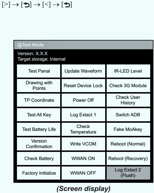
7. Confirm the HOME menu was completely displayed, and press the key as following order.
8. After a while, the test mode menu is displayed, and this unit enters the test mode.RELEASING THE TEST MODE
1. Press the [Return] key, and confirm the HOME menu was completely displayed.
2. Connect this unit to PC by the USB cable (MICRO B).
3. Confirm the USB connection screen displayed, and touch the “Data Transfer Mode”.
4. Confirm the “READER” drive of this unit is recognized.
5. Delete the file for the test mode from directly under the “READER” drive of this unit.
6. Remove this unit and USB cable (MICRO B) from PC.
7. Confirm the HOME menu was completely displayed, and press the key as following order, and confirm that the test mode does not enter. Press the buttons as you did to enter the test mode, as above to release it.
8. Press the [Power] key for 5 seconds or more, and touch the “Yes” to turn the power off.
Note: Never forget to delete the file for the test mode.
OPERATION OF EACH MODE
1. Test Panel
The panel can be checked.
1. Touch the “Test Panel” in the test mode menu.
2. The image file is displayed (image files of in the directly as “/testmode/images/”).
The format that can be treated is “.bmp”, “.jpeg” , “.gif” and “.png”.
The all image files are transformed into the 600 x 800 size, and the linear interpolation processing of pixel is done.
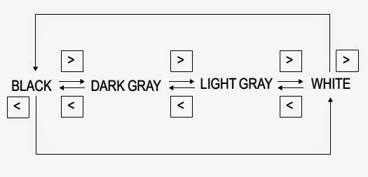
3. Press the [<]/[>] keys, the image files are changed.
Note: If there are no image files, the screen changes into gray scale color.
Press the [<]/[>] keys, the gray scale color changes sequentially as shown in the figure below.
Releasing method:
Press the [Return ] key, return to the test mode menu.
2. Drawing with Points
This mode is not used in servicing.
3. TP Coordinate
This mode is not used in servicing.
4. Test All Key
This mode is not used in servicing.
5. Test Battery Life
This mode is not used in servicing.
6. Version confirmation
This mode is not used in servicing.
7. Check Battery
This mode is not used in servicing.
↧
LOCK AND FACTORY INITIALIZE - SONY DIGITAL BOOK READER
Factory Initialize and Reset Device Lock
FACTORY INITIALIZE
FACTORY INITIALIZE
This unit can be returned to the state of the factory shipment.
Touch the “Factory Initialize” in the test mode menu. (To know how to enter test mode, refer previous post; here)
When “Yes” is touched, the deletion of all histories and reset of all settings are executed, and then this unit turns the power off.
Update Waveform
LUT rewriting and the LUT update confirmation can be executed.
As for INK INDICATOR 6inch ELEMENT, the parameter that rewrites the screen of each FPL lot number and TFT vender are different. This parameter is called LUT (Look Up Table). Therefore, you need to rewrite the LUT when replacing the complete MAIN board or CHASSIS ASSY (including INK INDICATOR 6inch ELEMENT).
However, rewriting is not required if the FPL lot number and TFT vender are the same.
Not Update Waveform
Note 1: LUT is written in IC2001 on the MAIN board.Procedure:
The LUT confirm method is different according to replaced parts.
When the complete MAIN board is replaced:
Disassemble this unit until the FPL lot number and TFT vender are seen, and confirm the FPL lot number and TFT vender referring to the figure below. Record the confirmed the FPL lot number and TFT vender by taking the memo etc.
When the CHASSIS ASSY (including INK INDICATOR 6inch ELEMENT) is replaced:
1. Confirm the FPL lot number and TFT vender described on the label of new CHASSIS ASSY (including INK INDICATOR 6inch ELEMENT). Record the confirmed the FPL lot number and TFT vender by taking the memo etc..
2. Replace complete MAIN board or CHASSIS ASSY (including INK INDICATOR 6inch ELEMENT) for new parts, and assemble this unit.
3. Confirm the following data to the service headquarters.
WF file corresponding to the recorded FPL lot number and TFT vender
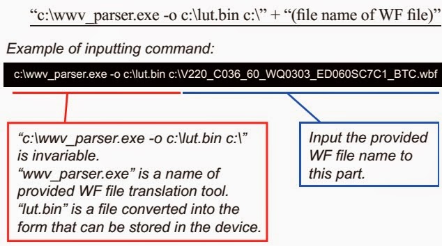
WF file translation tool (wwv_parser.exe)
4. Copy the file and the tool obtained in step 3 to directly under the C drive of PC (Windows XP or more is recommended)
5. Start the command prompt, and execute the following commands.
“c:\wwv_parser.exe -o c:\lut.bin c:\” + “(file name of WF file)”
The “lut.bin” file is generated to directly under the C drive.
6. Press the [Power] key to turn the power on.
7. Confirm the HOME menu was completely displayed, and connect this unit to PC by the USB cable (MICRO B).
8. Confirm the USB connection screen displayed, and touch the
“Data Transfer Mode”.
9. Confirm the “READER” drive of this unit is recognized.
10. Make the following folder under the “READER” drive of this unit.
/testmode/data/
11. Copy the “lut.bin” file made in step 5 to the “data” folder made in step 10.
12. Copy the file for the test mode from PC to directly under the “READER” drive of this unit.
Note 2: When the file for the test mode already exists directly under the “READER” drive of this unit, the file for the test mode need not be newly copied.
13. Remove this unit and USB cable (MICRO B) from PC.
14. Enter the test mode (Refer to “HOW TO ENTER THE TEST MODE” described by previous post here)
15. Touch the “Update Waveform” in the test mode menu, and confirm current (unrenewed) LUT version is displayed
16. Touch the “Yes”, it starts rewriting LUT version.
17. After about 10 seconds, screen changes into all white.
18. Press [RESET] key and reboot this unit.
19. Enter the test mode again, and confirm LUT version has been updated.
Reset Device Lock
When the Device Lock is effective, it can be released.
Note: When this mode is performed, it is necessary to reboot this unit and to validate the settings. Touch the “Reboot (Normal)” in the test mode menu.
1. Touch the “Reset Device Lock” in the test mode menu.
2. When the Device Lock is effective, the following screen is displayed. Touch the “Yes”, the Device Lock becomes invalid. It returns to the test mode menu when “No” is touched.
When the Device Lock is not effective, the following screen is displayed. Touch the “OK”, return to the test mode menu.
Power Off
This mode is not used in servicing.
Log Extract 1
This mode is not used in servicing.
Check Temperature
This mode is not used in servicing.
Write VCOM
In this mode, the VCOM voltage can be rewritten.
The VCOM voltage for INK INDICATOR 6inch ELEMENT is individually different.
Therefore, when replacing the complete MAIN board or CHASSIS ASSY (including INK INDICATOR 6inch ELEMENT) you need to rewrite the VCOM voltage.
Procedure:
1. The VCOM voltage confirm method is different according to replaced parts.
When the complete MAIN board is replaced:
Disassemble this unit until the VCOM voltage is seen, and confirm the VCOM voltage referring to the figure below. Record the confirmed the VCOM voltage by taking the memo etc..
When the CHASSIS ASSY (including INK INDICATOR 6inch ELEMENT) is replaced:
Confirm the VCOM voltage described on the label of new CHASSIS ASSY (including INK INDICATOR 6inch ELEMENT). Record the confirmed the VCOM voltage by taking the memo etc..
2. Replace complete MAIN board or CHASSIS ASSY (including INK INDICATOR 6inch ELEMENT) for new parts, and assemble this unit.
3. Make the text file on PC, and write the VCOM voltage confirmed in step 1.
Note 1: The VCOM voltage is described by the unit of mV that omits minus (Example: Write “2030” when it is printed on the label as “–2.03 V”).
4. Press the [1] key to turn the power on.
5. Confirm the HOME menu was completely displayed, and connect this unit to PC by the USB cable (MICRO B).
6. Confirm the USB connection screen displayed, and touch the “Data Transfer Mode”.
7. Confirm the “READER” drive of this unit is recognized.
8. Make the following folder under the “READER” drive of this unit.
/testmode/data/
9. Copy the text file made in step 3 to the “data” folder made in step 8. Then, change the file name to “Vcom.dt”.
10. Copy the file for the test mode from PC to directly under the “READER” drive of this unit.
Note 2: When the file for the test mode already exists directly under the “READER” drive of this unit, the file for the test mode need not be newly copied.
11. Remove this unit and USB cable (MICRO B) from PC.
12. Enter the test mode (Refer to “HOW TO ENTER THE TEST MODE”
13. Touch the “Write VCOM” in the test mode menu, and confirm current (unrenewed) VCOM voltage is displayed (Example: -1854 mV in the figure below).14. Touch the “Yes”, it starts rewriting the VCOM voltage.
15. Confirm the VCOM voltage has been updated.
WWAN ON
This mode is not used in servicing.
WWAN OFF
This mode is not used in servicing.
IR-LED Level
This mode is not used in servicing.
Check 3G Module
This mode is not used in servicing.
Check User History
This mode is not used in servicing.
Switch ADB
This mode is not used in servicing.
Fake MoAkey
This mode is not used in servicing.
Reboot (Normal)
This mode is not used in servicing.
Reboot (Recovery)
This mode is not used in servicing.
Log Extact 2 (Flush)
This mode is not used in servicing.
↧
↧
HOW TO DISASSEMBLE SONY DIGITAL BOOK READER
↧
DSC S700 - SONY Cyber-shot DIGITAL STILL CAMERA - How to Disassemble
↧
HOW TO DISASSEMBLE NIKON COOLPIX L10 DIGITAL CAMERA
DISASSEMBLE PROCEDURE ( Part-1)
* Remove the seven outer case screws on the left (2), bottom (3), and right (2) side of the camera.
* Pry open the case from its bottom left side. There will be a little resistance. Just use a butter knife at the bottom left (screen side) edge to pry it open. Note how/where the AV cover attaches to the case.* Remove the single small screw on the silver lanyard connector.
* Loosen the center electronics assembly from the front case by prying with a small screwdriver along the gray plastic on the left side of the camera.
* Remove the center electronics assembly from the front case by lifting it up and out from its bottom.
Note the front face with the battery compartment, lens assembly (note that mine is crooked/damaged), auto-focus illuminator, and flash assembly. Especially take note of the large green flash capacitor. DO NOT short the terminals of the capacitor to discharge it as you will damage it. Instead recommend slowly draining the capacitor of electricity by applying a voltmeter or some other resistive load until its voltage is discharged.
Now examine the top face of the assembly. Note the tape, and the three exposed screws. Remove and temporarily store these three screws.
* Peel back the center portion of the tape. You may have to tear a portion of the tape. You'll see two electrical contact points labeled C4+ and C4-. Use these to discharge the capacitor. You'll also notice a single screw that attaches the flash bulb to the camera. Leave this screw alone as it is unrelated to the disassembly of the camera. Reattach the tape.
Contd ......
↧


.jpg)







.jpg)



.jpg)


.jpg)





.jpg)


.jpg)
.jpg)



.jpg)


