Quantcast
Channel: Electro help
Viewing all 2033 articles
Browse latest View live

COOLPIX L-10 NIKON DIGITAL CAMERA - DISASSEMBLE PROCEDURE - 2

$
0
0
Part-2
* Now examine the back face of the assembly , taking note of the six exposed screws. Remove these screws, and store them.
* Gently flip the LCD screen and its metal holding bracket up and over to expose the circuitry beneath it. Do not disconnect the LCD screen's large ribbon cable. But do notice the three small recessed screws, and the smaller ribbon cable and its connector. Remove the three screws.
* Now notice the black hinge on the small ribbon connector. Swivel this black hinge upward with your finger nail. The small ribbon should now easily pull free. Note that the cable has no connector on its end once it's pulled free.
* Very carefully tug and lift the bottom of the circuit board. It should hinge upward as the battery leads bend and serve as the hinge point.
* Remove the three screws on the metal cover plate over the lens assembly. Take extra care not to damage any circuit board components, especially the exposed CCD. After the screws are removed, the cover plate and lens assembly should now easily lift out.
* Pry the metal cover plate from the lens assembly. Do this by inserting a small screw driver under one of its three clips, and then twist it. The clip should pop free. Repeat on the other two clips until the plate is removed.
* Remove the four screws that hold its back cover on. Remove the back cover.
*Examine the interior of the lens assembly for any anomalies that may indicate its malfunction. In the below example, two things are apparent. First is that the assembly's guide pins have been dislocated from their intended guide grooves (look at the 4 and 8 O’clock positions). The second problem is that some of the teeth on the lens assembly's primary gear are missing and damaged (as seen at the 2 O’clock position).
Repair is possible by forcing the guide pins back into their grooves. However, camera operation would still be degraded due to the missing gear teeth. It would be necessary to physically help the lens extend and retract during power up/shutdown by pulling or pushing it. Because of this, it was decided to withhold repair and reassembly until acquiring another broken L10. The intent would to salvage and replace the lens assembly with an undamaged one.


HOW TO TURN OFF SAFE MODE TO ANDROID T-MOBILE

$
0
0
TO WIPE CACHE PORTION

Wipe cache partition

  If the phone is not working correctly, you may need to master reset it and also clear the cache partition. These two resets clear different parts of the phone storage. Unlike a master reset, wiping the cache partition does not delete your personal data.
To wipe the cache partition, follow these steps:
  1. Power off the device.
  2. While pressing the Power key, simultaneously press the Volume Up key.
  3. Continue to press the keys past the T-Mobile splash screen.
  4. Release all keys when the Android system recovery screen appears.
  5. Press the Volume Down key to highlight Wipe cache partition.
  6. Press the Power key to select.
  7. Once the device shows Cache wipe complete, Press the Power key to select Reboot System Now.
  8. The phone will automatically restart.
Master reset from settings menu
A master reset restores the original factory settings and may delete your personal data on the internal storage, such as downloaded content, ringtones, images, apps,and contacts. It does not delete data stored on the SIM card or SD card.
To perform a master reset, follow these steps:
  1. Back up all data on the internal memory.
  2. From any Home screen, tap the Menu key.
  3. Tap Settings.
  4. Tap Privacy.
  5. Tap Factory data reset.
  6. Tap to check Erase SD card.
  7. Tap Reset phone.
  8. Tap Erase everything.

Master reset with hardware keys

  A master reset restores the original factory settings and may delete your personal data on the internal storage, such as downloaded content, ringtones, images, apps,and contacts. It does not delete data stored on the SIM card or SD card.
  If the device menus are frozen or unresponsive, you can master reset using hardware keys. To perform a master reset, follow these steps:
Back up all data on the internal memory.
  1. While pressing the Power key, simultaneously press the Volume Up key.
  2. Continue to press the keys past the T-Mobile splash screen.
  3. Release all keys when the Android system recovery  screen appears.
  4. Press the Volume Down key to highlight Wipe data/Factory Reset.
  5. Press the Power key to select.
  6. Press the Volume Down key to highlight Yes [--] delete all user data.
  7. Press the Power key to select.
  8. The unpacking Android screen appears, and once complete with the reset, the Android system recoveryscreen reappears.
  9. Press the Volume Down key to highlight reboot system now.
  10. Press the Power key to select.
  11. The phone will automatically restart.
Safe Mode

Turn on and use safe mode

  Safe mode allows you to turn on the device with third-party apps disabled. Then you can easily remove all apps that may be causing a conflict or software problem.
To turn on safe mode and use it to fix app problems, follow these steps:
  • Remove the battery from the phone.
  • Re-insert the battery.
  • Press and hold the Menu key.
  • While holding the Menu key, turn on the device.
  • When you see the lock screen, you can release the Menu key. ‘Safe mode' displays in the lower-left corner.
  • Uninstall any third-party apps that gave you problems

Turn off safe mode

To turn off safe mode, follow these steps:
  • Press and hold the Power key.
  • Touch Power off.
  • Remove the battery.
  • Re-insert the battery.
  • Press the Power key to turn on the device, but do not touch any keys during the restart.
Cannot turn off Safe mode: Android

'Safe mode' displays on bottom of the Home screen.  Cannot make calls or receive calls or access the internet

Some third-party apps do not start.
Possible causes
Third-party application or app cache prevents the device from starting properly
Case or gel skin on device touches the keys
Accidentally touching keys while device is starting, or keys get stuck
Phone is connected to cable and encounters an error
Device is rooted
Safe mode can automatically activate due to one of the above causes. You need to fix your cause and exit Safe mode to make calls, send and receive messages, or connect to the Internet.

Use Safe mode to stop a force close loop: Android

Understanding the Issue

Related errors
'Safe mode' displays on bottom of the Home screen
Cannot make calls or receive calls or access the internet
Some third-party apps do not start

  Safe mode only allows access to the device menus, without any connection to wireless networks and without starting some third-party apps. You need to exit Safe mode to make calls, send and receive messages, or connect to the internet.

  Safe mode can be used to stop a force close loop. A force close loop is when an app automatically force closes, then opens and closes continuously. Since you cannot access any of Android menus while in a force close loop, there is no way to close it. Placing a phone into Safe mode stops the loop and allows you to remove the app without a master reset.

Turn on Safe mode

  To turn on Safe mode for all Android devices except the myTouch by LG and myTouch Q by LG, follow these steps:
  1. Remove the battery from the phone.
  2. Re-insert the battery.
  3. Press and hold the Menu key.
  4. While holding the Menu key, turn on the device.
  5. When you see the lock screen, you can release the Menu key.
  6. 'Safe mode' displays in the lower-left corner.

  If restarting the device does not turn off Safe mode, follow these steps: Verify the phone is unplugged and not charging.

  1. Remove the battery and SIM card.
  2. Wait at least 20 seconds so there is no charge left in the phone.
  3. Re-insert the SIM card and the battery.
  4. Make sure the Menu key is not being touched by a case or gel skin.
  5. Press the Menu key a few times to verify it is not stuck.
  6. Turn on the device.Note: Do not press any keys while the phone is starting.
  7. If the device still starts in Safe Mode, then uninstall all apps that you recently downloaded.
  8. Restart the device. Note: If the device restarts, the issue was with one of the third-party apps. If you know which one it was, contact the developer or review the app to give feedback.
  9. If the device is still in Safe mode, wipe the cache partition.
  10. If the device is still in Safe mode, perform a master reset using hardware keys.

Back up contacts

To back up your contacts, follow these steps:
  1. From any Home screen, tap the Menu key.
  2. Tap Settings.
  3. Tap Accounts & sync.
  4. Tap the account you would like to sync.
  5. Tap to select or clear the desired check boxes.
  6. Tap Sync now.

To back up your media and pictures, follow these steps:

  • Connect the phone to your computer using the USB cable.
  • Tap Turn on USB storage.
  • Tap OK.
  • On the computer, navigate to and open the phone’s disk drive.
  • Click to open the desired file(s).
  • Copy the files you want to move.
  • Paste the files in the desired location on the computer.
  • When finished, safely disconnect the phone from the computer.
  • Tap Turn off USB storage.
BACKUP AND RESTORE

To back up your apps, follow these steps:

Back up contacts

  1. To back up your contacts, follow these steps:
  2. From any Home screen, tap the Menu key.
  3. Tap Settings.
  4. Tap Accounts & synch.
  5. Tap the account you would like to sync.
  6. Tap to select or clear the desired check boxes.
  7. Tap Sync now.

Back up media & pictures

To back up your media and pictures, follow these steps:
  1. Connect the phone to your computer using the USB cable.
  2. Tap Turn on USB storage.
  3. Tap OK.
  4. On the computer, navigate to and open the phone’s disk drive.
  5. Click to open the desired file(s).
  6. Copy the files you want to move.
  7. Paste the files in the desired location on the computer.
  8. When finished, safely disconnect the phone from the computer.
  9. Tap Turn off USB storage.
RESTORE DATA: Restore apps
To restore backed up apps, follow these steps:
Your apps will restore automatically upon the next time you sign into your Gmail account.
Restore contacts
To restore backed up contacts, follow these steps:
Your apps will restore automatically upon the next time you sign into your Gmail account.
Restore media & picture
To restore backed up media and pictures, follow these steps: Connect the phone to your computer using the USB cable.
  • Tap Turn on USB storage.
  • Tap OK.
  • On the computer, navigate to and open the phone’s disk drive.
  • Navigate to and move the desired file(s).
  • When finished, safely disconnect the phone from the computer.
  • Tap Turn off USB storage.

PANASONIC TC-L32C30B - LCD TV - POWER SUPPLY SCHEMATIC (Circuit Diagram)

$
0
0
SMPS SCHEMATIC & PWB(Click on the pictures to Magnify)

PANASONIC TC-L42U30B LCD TV - POWER SUPPLY CIRCUIT DIAGRAM (Schematic) TNP4G498

$
0
0
SMPS (POWER SUPPLY) SCHEMATIC _ [Click on the Pictures to Zoom In]

HOW TO DISASSEMBLE SAMSUNG SyncMaster 920NW – 19” LCD MONITOR

$
0
0
DISASSEMBLY {Click on the Pictures to Magnify}

SAMSUNG SyncMaster - 19" LCD MONITOR - POWER AND INVERTER SCHEMATIC

$
0
0
SMPS SCHEMATIC(Click on the Schematics to Zoom In)

HOW TO DISASSEMBLE SAMSUNG GT-i9100 GSM TELEPHONE

$
0
0
DIS-ASSEMBLY
* Carefully release the screws at 7 different locations from the rear cover. (Torque:1.1±0.1kgf.cm)(Size: M1.4*L3)
* Disengage the rear cover from the front cover by using the hook at 12 points that colored in red (Follow the numbered sequence when you disjoint)
* Separate the coaxial cable of antenna assembly from the PBA.  Release the screw at 2 points(Size: M1.4*L3) (Torque:1.1±0.1kgf.cm)
* Detach the side FPCBs from the Bracket.
* Separate all connector ribbons from the PBA.  Separate the PBA from the Front.
* Release the screw at 2 points (Size: M1.4*L2)(Torque:1.1±0.1kgf.cm)
* Separate the sub PBA from the PBA.
* Separate the Receiver assembly from the Front.
(Insert along nose tweezers into the holes for easy separation.)  Be careful not to damage the FPCBs.
CLICK ON THE PICTURES TO MAGNIFY

HOW TO INSTALL SOFTWARE - SAMSUNG GT-i9100 GSM TELEPHONE

$
0
0
FIRMWARE [Software] INSTALLATION 
Required items in order to install S/W
  1. Installation program: Downloader Program (Odin3 v1.83.exe)
  2. GT-i9100 Mobile Phone
  3. Data Cable
  4. JIG BOX(GH99-36900B)
  5. JIG Cable(GH39-01339A)
  6. Adapter(GH99-38251A)
  7. Serial Cable
  8. Mobile device specific S/W:Binary files.
Settings
Connect ANYWAY JIG BOX with JIG CABLE (Phone to JIG) or PC to Phone Using Data Cable.
S/W Installation Program (Down-loader program)
Open up the S/W Installation Program by executing the"Odin3 v1.83.exe"
Enable the check mark by click on the following options,
Check Re-Partition, Auto Reboot, and F. Reset Time
Check PIT
Check PDA, PHONE, and CSC Files
S/W installation
Enter into Download Mode
Enter into Download Mode by pressing Volume Down button, OK button, and ON/OFF Button simultaneously.
Connect the device to PC via Data Cable.
Make sure that the one of communication port[ID:COM] box is highlighted in yellow. The device is now connected with the PC and ready to download the binary file into the device.
Start downloading binary file into the device by clicking Start Button on the screen.  the green colored "PASS!" sign will appear on the upper-left box if the binary file has been successfully downloaded into the device.
Disconnect the device from the Data cable.
Once the device boots up, you can check the version of the binary file or name by pressing the following code in sequence; [*#1234#]
You can perform full reset by pressing the following code in sequence; [*2767*3855#]


BBK N4302[RU] – TROUBLESHOOTING CHART - GPS

$
0
0
TROUBLESHOOTING
CLICK ON THE CHARTS TO ZOOM IN

JBL BP1200.1 - CAR AMPLIFIER - SCHEMATIC (Circuit Diagram)

$
0
0
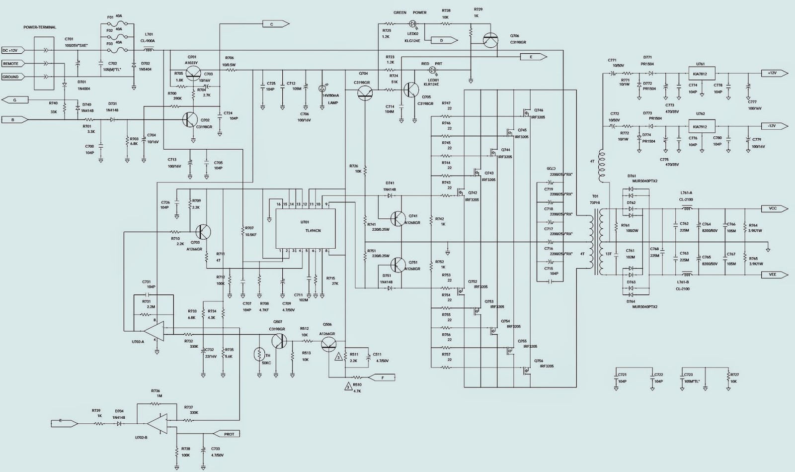
JBL Power supply / Input – Crossover – Power Amplifier _ Schematic (Circuit Diagram)
SPECIFICATIONS
Number of Channels . . . . . . . . … 1
4 Ohms . . . . . . . . . . . . . . . . . . …… 600W
2 Ohms . . . . . . . . . . . . . . . . . ………1200W
T.H.D. @ 4 Ohms rated Power . .  0.10%
Frequency Response . . . . . . . . . . 10Hz ~ 320 Hz
Signal to noise Ratio . . . . . . . . . . . >100dB
Maximum Current Draw . …………114A
Fuse size. . . . . . . . . . . . . . . ………… 40A x 3
Input Sensitivity. . …….. . . . . . . . .250mV ~ 4V
Minimum Speaker Impedance…1 ohm
External Dimensions
Length . . . . . . . . . . . . ……………….14 13/16 (376mm)
Width . . . . . . . . . . . . . . . . . . . . . . 10 3/16 (274mm)
Depth . . . . . . . . . . . . . . . . . . . . . . 2 11/16 (68mm)
Under certain large signal conditions during intense bass passages, the unit will go into protection. These amplifiers are behaving as designed. As the unit is driven into hard clipping, the protection circuit found in BP Series amps was engineered to protect your loudspeakers from being destroyed by a severely clipped output signal. This can be remedied easily by turning the volume down somewhat on your music source.  In the event you receive a BP series amplifier with the complaint: “Under a large signal input, with music that is composed of high-level bass, the amplifier mutes for 2-3 seconds, and then returns to normal operation”, the following modification will effectively increase the amount of clipping that is allowed to occur before the protection circuit engages by increasing the threshold at which the amplifier mutes - for the benefit of customers who use the amps in SPL competition, or for customers who insist on driving the amplifiers into this potentially hazardous zone.
1  Turn the amplifier upside-down and remove the Phillips screws holding the bottom cover on.
2  Locate and change R510 from 47K to 4.7K ohms 1/5W (JBL part# RE212047200).
3  Locate and change R511 from 22K to 2.2K ohms 1/4W (JBL part# QAF0450-222).
4  If it is not already present, add new part - 4.7uf 50v electrolytic capacitor (JLB part# EC070114760) in parallel with R511. Polarity: The negative side of the Capacitor must be connected to the junction of R510/R511, which can be discovered with an ohmmeter.
NOTE: Using the correct soldering techniques, you should be able to make these changes from the top of the PCB without its removal.
5) Replace bottom cover; test amplifier.
POWER SUPPLY SCHEMATIC
INPUT - CROSSOVER - POWER AMP

WIRING DIAGRAM - JBL BP1200.1 1 CHANNEL POWER AMPLIFIER

$
0
0
WIRING
Note the Ground point of Wiring.  A Single Point Ground is a must.  Even though the chassis of  the vehicle as a whole is (-ve), never connect the ground wire to other than specified point here.  All the 4 ground wires should be connected to this point, as shown in figure; otherwise, Audio Distortion will occur, especially to higher volume levels.

1. It allows left and right input channels to be connected to the amplifier using RCA plugs.
2. Speaker Output Connector - Connect speaker wiring to these connectors.
3. Fuse - 40Ax3 Amp ATC type Fuses.
4. Power Connection for 12V+, GND and REM connections for power wires.
5. Input-Level Control - Adjusts input sensitivity for pre-amp level and speaker level inputs.
6. The electronic crossover is a 12dB/oct. Low pass filter which can be set at any frequency between 32Hz and 320Hz.
7. The bass boost control will provide up to 6dB of boost at 50Hz.
8. It allows left and right input channels such as high level speaker output signals to be the amplifier.
9. The JBL BP Series amplifiers can be mounted in virtually any location inside the vehicle.  However, make sure to keep the amplifier away from heater vents or ducts.
* At the chosen site, use the amplifier as a mounting template and mark the locations of the four mounting holes.
* Drill a small pilot hole at each marked location.
* Mount the amplifier and securely tighten the mounting screws. 
   Never allow any metal part of the amp's case, to come in contact with the metal body of the vehicle; to avoid an alternate 'Ground' connection other than specified by the wiring diagram.  Use non conductive material to attach the Amp with vehicle.  Do the same with all other attached devices with amplifier. 


INFINITY BU-1 - SCHEMATIC - POWERED SUB-WOOFR

$
0
0
EXPLODED VIEW
SPECIFICATIONS
Driver è8"Woofer
Nominal Impedanceè4
Enclosure Design è Tuned Port
Amplifier Power è 50watts RMS
Frequency Response è 45Hz - 150Hz (± 3dB)
Crossover Frequency è 50to150HzContinuously Variable
Inputs
Line Level  è RCAjacks
High Level è (Speaker) Input terminals
Outputs è Full range Speaker
Sensitivity
Low Level è 50mV
High level è 1V
Input Impedance
Low Level è 10k
High level è 4.7k
Dimensions
Inches è 11½x11½x11½"
Metric  è 29.2 x 29.2 x 29.2cm plus 1¼" (32mm) for feet)
Auto Power
This Auto On/Off switch controls whether the BU1’s Automatic turn-on circuit is active. When the switch is ON, the BU1 will turn itself on, indicated by a green LED, when it is plugged in and receiving a signal. When the BU1 has not received a signal for approximately ten minutes, the unit will revert to the STANDBY mode, indicated by a red LED. When this switch is OFF, the unit will revert to the STANDBY mode and will stay OFF, regardless of input signal. THIS IS NOT
A TRUE AC POWER SWITCH AS IT DOES NOT DISCONNECT THE AMPLIFIER FROM THE 120VAC LINE.
High Level Inputs
These High Level Inputs are for receivers that do not have line-level “pre-amp out” or “subwoofer out” jacks. When a pair of main or satellite speakers are attached to the OUTPUT terminals, they are driven the full range of frequencies as generated by the music source (receiver, amplifier, etc.)
Low Level Input
These left and right Line Level Inputs are normally used when the receiver/processor has line-level “pre-amp out” or “sub-woofer out” jacks. If a single cable mono
or sub-woofer source is connected to the BU1, a Y-cable must be connected to the sub-woofer for full output.
Volume Control
This controls the volume level of the sub-woofer.
 Frequency
 The Frequency adjustment determines the upper corner roll-off point for the BU1.
{If a problem you are experiencing is a common (although not serious) one. It seems the "standby", or muting circuit for the BU-1 subwoofer is very sensitive. It senses any small voltage at either the low level or high level inputs as an input signal and will turn the unit on. This includes above-average DC offset on the customer's receiver/power amplifier, small amounts of 60 Hz hum or noise picked up by the customer's input cables, etc. Since the initial testing and development of the unit involved high quality audio equipment and connections, this tendency did not surface at that time.  The muting, or stand-by circuit electronically shuts down the bias voltages to the amplifier section. It does not turn off the unit's power supply. When the unit is idle it's drawing about as much power as a 17 watt light bulb, whether or not the muting circuit is activated. So the unit is electrically safe to leave turned on constantly no matter what color the LED is at the time, and of course sonically it's completely harmless.  This is not a serious problem.}
PRE-AMP SCHEMATIC
POWER AMP SCHEMATIC
230V_FEATURE
CLICK ON THE PICTURES TO MAGNIFY

BBK DIGITAL PHOTOFRAME - LM2005W - LM2205W - POWER SUPPLY SCHEMATIC

$
0
0

SMPS
Trouble shooting for usual failures:
Unable to burn and record
The 12V power provided to the AD board by the power supply board is normal, and the connection of the VGA signal wire is good, but the program cannot be burnt and recorded. Check as the following steps:
* Firstly check whether the power supply system on the main board is normal or not. Whether the U4 output is 3.3V?
* After the power supply is normal, firstly measure whether the crystal vibrator X2 starts to vibrate or not, and use the oscillograph to measure whether Y2 exports the pulse wave? (If no oscillograph, use the multimeter to measure the voltage on both sides of Y1)
* After the vibrator normally works, check whether there are signals being transmitted on Pins 1, 2, 5 and 6 on U8 (PM25LV512)
White screen
Firstly we should know what the white screen is? Why there will be a white screen? The phenomenon of the white screen is that the panel emits the white light, but has no any picture. The reason is the crystal screen does not work normally: The back-light source (Tube) of the screen is working normally, but the crystal screen does not work. Although the screen emits light, that is just that the tube is on.
* Check whether the 3.3V power supply around the main IC is normal or not.
* Measure whether X1 starts vibrating? (If the button switch is ok, this check can be omitted)
* Measure the input and the output on the U4 of the MOS tube that supplies power to the screen.  In most cases, the reason of the white screen is the abnormal power supply for the screen, so after finding out where cannot supply power to the screen, you can easily solve the problem of the white screen.
Disorderly screen
Disorderly screen is that the control buttons for OSD are all OK, and the screen is on, but the picture is abnormal, having the phenomena of coarse pictures, grains and disorderly picture, etc.  Due to the OSD controls are OK, it means the main IC works normally, the key point should be on the input & output sides of the signals.
* Start up the aging signals, to check whether the black, white, R, G and B outputs are OK or not, to find out whether there is a problem in the front input or the back input, and then check whether the input or output circuit has the short circuit or the bad component accordingly.
If there is no problem in the fore said positions, the main chip can be replaced.
No signal
It works normally when using the aging signals, but when inserting the signals, it display No Signal (No signal input). The normal work of the aging signals means the MCU is working normally, and the signal output circuit is normal. At this moment, it only needs to check whether the signal input circuit is OK or not, and at last, consider replacing the main chip.
Black screen
Black screen here means the crystal screen is not on at all, but the button board can control switches. In most cases, the reason of the black screen is that the tube does not work, so the focus should be to check whether there is voltage on On/Off that controls the work of the inverter on the power supply board.
* Firstly, press the power button to start, measure whether it is in the high voltage level (3.3V) of the inverter on Pin 3 of CON3? If not, check whether the input & output voltage on Q2 is normal or not, and whether the PANEL_LIGHT/ON output extending to the main IC is in the low voltage level (0V) or not?
* If the voltage on the PANEL_LIGHT/ON is normal, then you can determine the inverter on the power supply board has the problem.
Color deflection
The picture display is normal, but the color is not pure, deflecting to red, green and blue. For color deflection, it is important to determine whether it is caused by input or output.
* Firstly, make judgment. Start up the aging signals, and observe whether the outputs of black, white, R, G and B are OK or not, and if the color is normal, it means there is no problem on the signal output circuit, and the input circuit of the front signal is broken, otherwise, it means the input circuit for the back signals has the problem.
For the input circuit of the front signal, check whether it has the problems of short circuit or holiday in focus, and then check whether the resistance values of various components are correct or not.
For the output circuit of the back signals, it only needs to check whether it has the problems of short circuit or the holiday and whether the circuit is open.  DDC cannot be burnt and recorded
DDC is saved in PM25L512, which is burnt and recorded into the MCU through two pins of DAT_DDC_VGA and CLK_DDC_VGA on the VGA signal wire, and then saved in U8, so it only needs to check whether the power supply to U8 and the communication between the main IC and the U8 are OK or not, and at last, you can consider replacing the U8.
Sound source inspection
When there is no sound, firstly check whether the power supply is normal or not, AUDIO_MUT (Whether the mute signal is normal or not) and whether there are signal inputs in the sound-source input part, and finally, check the signal output part. After all are normal, and then confirm ICNC.
 If it cannot be adjusted, check whether the VOL signals are normal or not.

VIEWSONIC N2060 - 20 INCH TV-MONITOR - SCHEMATIC DIAGRAM - POWER [SMPS]

$
0
0
VIEWSONICAOC KIT 20” LCD TV COLOR MONITOR - 2060W-1M – 2060W-1G – 2060W-1E (Factory Preset Display Modes)
SMPS SCHEMATIC 
FACTORY PRESET DISPLAY MODES
CLICK ON THE PICTURES TO MAGNIFY

ERROR CODES - FD Trintron - SONY KV-32FX66K - KV-28FX66E - HOW TO ENTER SERVICE MODE - ADJUSTMENTS

$
0
0
ERROR CODES
  The identification of errors within the AE-6B chassis is triggered in one of two ways :- 1: Busy or 2: Device failure to respond to IIC. In the event of one of these situations arising the software will first try to release the bus if busy (Failure to do so will report with a continuous flashing LED) and then communicate with each device in turn to establish if a device is faulty. If a device is found to be faulty the relevant device number will be displayed through the LED (Series of flashes which must be counted) (See table), non fatal errors are reported using this method.
TO ENTER INTO TABLE-2
  1. Turn on the main power switch of the TV set.
  2. Program Remote Commander for Operation in Service Mode.
  3. Press ‘VIDEO’ ‘VIDEO’ > ‘MENU’ on the Remote Commander.
  4. Using the Remote Commander, Scroll to the ‘Error Menu’ item using the down arrow key, then press the right arrow key.  The following table will be displayed indicating the error count.
APPLICABLE TO 
KV-28FX66B [RM-937 FR SCC-Q83H-A]
KV-28FX66E [RM-937 ESP SCC-Q81K-A]
KV-28FX66U [RM-937 UK SCC-Q84F-A]
KV-32FX66B [RM-937 FR SCC-Q83G-A]
KV-32FX66E [RM-937 ESP SCC-Q81J-A]
KV-32FX66K [RM-937 OIRT SCC-Q82E-A]
KV-32FX66U [RM-937 UK SCC-Q84E-A]
Service adjustments to this model can be performed using the supplied remote Commander RM-937.
1. Press the VCR/TV/DVD button until the TV LED lights.
2. Press and hold the yellow button for approx. 5 seconds until the TV LED flashes quickly.
3. Press  99999. All three LED’s should light.  The remote commander is now set to Service Mode.
To return the remote commander to normal operation mode repeat steps 1. and 2. then press 00000. All three LED’s should light.  The remote commander is now set to normal mode.
Setting TV into Service Mode
Program the remote commander for operation in Service Mode as described above.
  1. Turn on the TV main power switch.
  2. Press the video standby button on the remote commander twice.  ‘TT ’ will appear in the upper right corner of the screen. Other status information will also be displayed.
  3. Press ‘MENU’ on the remote commander to obtain the following menu on the screen.
  4. Move to the corresponding adjustment item using the up or down arrow buttons on the Remote Commander.
  5. Press the right arrow button to enter into the required menu item.
  6. Press the ‘Menu’ button on the Remote Commander to quit the Service Mode when all adjustments have been completed.
Note:  After carrying out the service adjustments, to prevent the customer accessing the ‘Service Menu’ switch the TV set OFF and then ON.


Sony KV 28 / 32FX66 – FD Trinitron – Picture Geometry [Deflection System] Adjustment

$
0
0
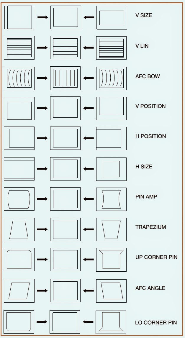
PICTURE GEOMETRY ADJUSTMENT
* Program the Remote Commander for operation in Service Mode.
* Enter into the ‘Geometry’ service menu.
* Select and adjust each item in order to obtain the optimum image.  (See the previous article here to know how to enter service mode)
TEST MODE - 2
Test Mode 2 is available by programming the Remote Commander for operation in Service Mode then pressing the ‘VIDEO’ button twice, OSD ‘TT’ appears. The functions described below are available by selecting the two numbers. 
To release the ‘Test mode ‘2’, press 00, 10, 20 ... twice or switch the TV set into Stand-by mode. 
In ‘TT Menu’ mode, it is possible to remove the Menu from the screen by pressing the Speaker Off button once. Pressing the Speaker OFF button a second time will cause the Menu to reappear.  The function is kept even when the menu is not displayed on screen.

HOW TO OPEN [DISASSEMBLE] - SONY KV-28FX66 – KV32FX66 FD Trintron

$
0
0
Applicable to: Sony FD Trinitron KV-28FX66B _ KV-28FX66E _ KV-28FX66U _ KV-32FX66B _ KV-32FX66E _ KV-32FX66K _ KV-32FX66U
Rear Cover removal
  Remove the rear cover fixing screws indicated. Take care when removing the rear cover not to damage the speaker cables [Disconnect the speaker connector] as speakers are fitted inside the rear cover.  Before completely removing the rear cover disconnect the speaker connector which is located on the inside.
Chassis removal & refitting
  To remove lift the main bracket rear slightly and slide the chassis away from the beznet. Ensure that the interconnecting leads are released from their purse locks to prevent damage being caused.  When refitting the chassis ensure that the main bracket is located in the beznet guide slots before sliding the chassis forwards. Refit the interconnecting leads in their respective purse locks.
Service position & G-Board removal
  Position the chassis as indicated to access the solder side.  To remove the G Board release the clips circled and ease the board gently away from the support bracket.
D-2 Board & D-Board removal
  To remove the D2 board remove the two screws circled, release the clips circled and ease the board gently away from the support bracket.  To remove the D board first remove the D2 bracket by removing the two screws (one on each side of the bracket) and releasing the four clips (two on each side of the bracket). The D board can then be removed using the same method as the G board.
Side Control Module & H2 Board removal
  Remove the two screws fixing the user control module to the side of the set. The control module can then be removed by sliding it towards the rear of the set allowing access to the H2 Board.  To remove the H2 Board release the two clips circled and ease the board gently away from the support bracket.
M-2 Board & Service Connector removal
  To remove the M2 Board gently release the two clips with a screwdriver and remove the board from its socket vertically.  If the M2 Board needs to be removed for testing when the chassis is placed in its service position, it would be necessary to use an extender board and extension cable as indicated.
The Extender board and extension cable are available as a service part by ordering the part number.

POWER SUPPLY [SMPS] SCHEMATIC - Sony FD Trinitron – KV32FX66 – KV28FX66

$
0
0
G -Board _ Click on the Pictures to Magnify

HOW TO BYPASS DVD LOCK - BOSE BOSE 3.2.1 II SYSTEM

$
0
0
Setting a password restriction level. 
Your password will prevent unauthorized viewing of DVD videos that have a higher rating than your restriction level. There are 8 levels to choose from, matched to movie ratings set by the Motion Picture Association of America (MPAA).
* Turn on your TV and select the correct TV input to view your 3.2.1 system.
* Press the System button on your 3.2.1 remote control.
* Using the right [►] and left [◄] arrow buttons, highlight the DVD Lock option.
* Press Enter or the down arrow key V. Note: If you are using the DVD Lock option for the first time, enter a four-digit password. Then enter it again to confirm. Enter your four-digit password.
* Using the down▼ button, scroll down to Lock Discs Rated Above. Press the right [►] arrow button to see the available settings.
* Press the up arrow or down [▲/▼] button to find the rating you want.
* Press Enter or the left arrow [◄] button to save the setting.
* Press Exit to dismiss the Settings menu.
Example: Choosing a Parental Control Setting of 4, restricts access to videos rated above PG-13. Videos with ratings above that may be viewed only after entering the password.
DVD Lock options
The DVD Lock options allow you to restrict viewing of DVD videos with certain ratings. To activate this feature, you need to set a level of restriction and establish a password in the DVD Lock section of the System menu.
DVD Lock Bypass
If a customer forgets his DVD Lock password, or if you have a system in for repair that is locked and will not let you play a DVD without a password, you can bypass the DVD Lock feature by following the steps below.
* Select a non-DVD source and press the SYSTEM button on the remote.
* Navigate to the “DVD Lock” icon on the far right of the TV screen and press ENTER.
* The system will then request the user to enter a password. On the remote control, punch in the bypass code, which is 2673. This is a backdoor password for entering this menu only, not for allowing discs to play.
* After the bypass password is entered, you will be able to change settings in the “DVD Lock” menu.
* If you want to be able to play discs of all ratings, select OFF for “Lock Unrated Discs” and “8” for “Lock Discs Rated Above.” This will allow for all discs to play.
* If you wish to have the parental control engaged, refer to the table on the previous page for ratings restriction definitions and options.
Obtaining System Information from the Media Center Display
You can obtain system information directly from the media center display by pressing a few buttons. Follow the steps below.
Connect the media center and bass module as instructed in the owner’s guide.
Connect the system to AC mains.
With the media center turned off, press and hold the ENTER button on the media center.
When holding down the ENTER button, pressing the ON/OFF button will bring up the console system information on the console display. For each additional press of the ON/OFF button, you will get additional information. See the list below.
Once you are done viewing the information, press the POWER button to clear the display.
Video Format:
Press the ON/OFF button down once. You should see the video format information, similar to VIDEO: NTSC COMPOSITE + S. This indicates the video format the console is set to.
Console Software Revision:
Press the ON/OFF button a second time. You should see the console software revision, similar to CON: 01.01.05, which indicates that the console software
revision is 01.01.05.
Console Variant Information:
Press the ON/OFF button a third time. You should see the console variant information, similar to the following. CONSOLE VARIANT: 129.
Bass Module Software Revision:
Press the ON/OFF button a fourth time. You should see the bass module software revision level, similar to BASS BOX SOFTWARE: 0101BF.
Tuner PCB Software Revision:
Press the ON/OFF button a fifth time. You should see the tuner software revision level, similar to TUNER SOFTWARE: 01.00.BC.
Console Serial Number:
Press the ON/OFF button a sixth time. You should see the console serial number level, similar to CONSOLE SERIAL #: 035666941400018AZ.
Console Main PCB Serial Number:
Press the ON/OFF button a seventh time. You should see the main PCB serial number, similar to MAIN BOARD SERIAL #: xxxxxxxxxxx274256xx0001.
Console Tuner PCB Serial Number:
Press the ON/OFF button an eighth time. You should see the tuner PCB serial number, similar to TUNER BOARD SERIAL #: xxxxxxxxxxx274257xx0001.
Console Region Code Setting:
Press the ON/OFF button a ninth time. You should see the console region code setting, similar to DVD REGION CODE 1.
Console DVD Drive Software Revision and Hardware Information:
Press the ON/OFF button a tenth time. You should see the DVD drive software level and drive information, similar to DVD DRIVE: 1B10 IBA DVD-ROM SD-M1712.
Console Main PCB Test Information:
Press the ON/OFF button an eleventh time. You should see the test information for the console main PCB, similar to MAIN BD FUNCTIONAL: PASSED.
Console Tuner PCB Alignment Information:
Press the ON/OFF button a twelfth time. You should see the tuner PCB alignment information, similar to TUNER BD ALIGNMENT: FF.
Console Serial Port (BoseLink Port ) Information:
Press the ON/OFF button a thirteenth time. You should see the serial port information, similar to SERIAL PORT: SMART SPEAKER.

HOW TO DISASSEMBLE BOSE 3.2.1 and 3.2.1GS Series II - Home Entertainment System

$
0
0
BOSE 3.2.1 and 3.2.1GS Series II - Home Entertainment System. (US/Canada Standard Versions, 120V and Dual Voltage)
DISASSEMBLE PROCEDURE
Outer Bezel Removal
Remove the DVD drawer bezel. To do this, you will need to either apply power to the console and press the EJECT button, or use the manual DVD drawer eject function.  This is done by placing a small screwdriver into the front of the slot located in the bottom of the bezel sub-assembly and rapidly moving the screwdriver toward the rear of the console. This will press in the built-in eject pin and cause the DVD drawer to open.
Gently unclip the DVD drawer bezel from the front of the DVD drawer and lift it off.
Close the DVD drawer.  IMPORTANT NOTE: If you close the drawer manually with no power applied, it will not latch properly. Once you have repaired the unit, make sure to apply power to the console and cycle the drawer open and closed to properly latch it in place before returning it to the customer. Failure to do this will cause the drive to be damaged in shipment.
On the bottom edge of the outer bezel assembly, lift the bezel edge away from the console slightly. Lift the top edge of the outer bezel assembly away from the console slightly. It should lift off and away from the console, revealing the button PCB, the IR PCB (located below the center of the button PCB) and the display PCB assembly.
Top Cover Removal.
Place the console onto a soft surface with the bottom facing upward. Using a Phillips-head screwdriver, remove the six screws that secure the top cover to the Base.
Grasp the console between the top and bottom of the unit, ensuring that you have a good grip on the unit, and carefully flip the console over onto its feet. Lift the top cover straight off.
Inner Bezel Sub-assembly Removal (includes Button PCB, IR Receiver PCB and Display PCB)
Unplug the inner bezel sub-assembly ribbon cables from J6500 and J6700 on the main PCB.
Using a Phillips-head screwdriver, remove the three screws that secure the bezel to the console. There is one screw at each end of the bezel and one in the center below the IR receiver.
Lift off the bezel. The button PCB, IR receiver PCB and display PCB will come off with the bezel.
The IR receiver PCB is connected to the button PCB by a ribbon cable. To remove it, unplug the ribbon cable at the button PCB end, and use a small flat-tip screwdriver to push back the small plastic arm that retains the PCB in the bezel. Lift out the PCB.
The button PCB is retained in the top of the bezel. To remove it, unplug the IR receiver PCB ribbon cable and the button PCB ribbon cable. Once the ribbon cable is
unplugged, press upward on the ribbon cable connector on the underside of the bezel top edge. The button PCB should slide off of the bezel posts.
The display PCB assembly is located in the right side of the bezel. To remove it, lay the bezel face-down. Use a small flat-tip screwdriver to release the display PCB from the four retaining clips. Lift out the display PCB assembly. Note: The display PCB assembly is not repairable. You must replace it as an assembly if it is defective.
Tuner PCB Removal.
Lift up on the forward edge and slide it toward the front of the console until the PCB jacks clear the rear panel. Lift the PCB straight up.
Unplug the tuner PCB ribbon cable from J6000 on the main PCB.
Re-assembly Notes:
Make sure that the RF gasket is in place on the FM antenna connector when re-installing the PCB assembly.
Make sure that the FM RF connector is centered in the opening in the rear panel before tightening the top cover screws.
DVD/CD Drive Removal
Unplug the drive power cable from J3202 on the main PCB.
Unplug the ATAPI cable from J3200 on the main PCB.
Lift the drive and the drive mounting bracket out of the console.  Note: The drive mounting bracket is the plastic bracket that the drive is mounted to that also goes over the main PCB to support the tuner PCB.
Make a note of the distance the front of the drive overhangs the front edge of the bracket. You will need to align the new drive in the same way, within about 1/16” (2mm).  Failure to do this will cause the DVD drive drawer bezel to not line up properly with the LCD display bezel on the front of the console when re-assembled.
Remove the four screws that secure the drive to the drive mounting bracket. Remove the DVD drawer eject pin from the manual eject hole in the front of the drive. Retain this pin for the new drive.  Re-assembly Note: Be sure to install the DVD drawer eject pin into the manual eject hole in the front of the drive before re-installing the bezel assembly.
CLICK ON THE PICTURES TO MAGNIFY

Viewing all 2033 articles
Browse latest View live