Quantcast
Channel: Electro help
Viewing all 2033 articles
Browse latest View live

HOW TO CHANGE REGION CODE - BOSE 3.2.1 - BOSE WAVE RADIO TROUBLESHOOTING

$
0
0
BOSE WAVE RADIO/CD TROUBLESHOOTING GUIDE _  HOW TO CHANGE REGION CODE-BOSE 3.2.1
WAVE RADIO _ TROUBLESHOOTING
* Dead Unit. 1.  Fuse F1 open. 2.  Un seated J1. 3.  Open power transformer.  1.  Replace fuse F1.  2.  Reconnect J1. 3.  Replace power transformer.
* Unit turns on/off by itself.  CD door defective.  Replace the CD door assembly.
* Intermittent or inoperable FM/AM.  Depending on date code, defective CF303 and C341, C342 or fractured solder joints on CF303.  1.  In units built before 5/4/99, replace CF303 with a 7.2 MHz crystal, part number 250892-001 and C341 and C342 with 27pF capacitors part number 133622-270. After soldering CF303, be sure to clip the leads.  2.  In units built after 5/4/99, check for fractured solder joints on CF303 and make sure the leads have been clipped.
* Constant hum on AM/FM.  Power supply capacitor C205 may be installed with reverse polarity.  Replace capacitor C205 part number 144000-471V.
* Hum on all sources.  Reversed C202 or C205.  Replace C202 or C205.
* The CD player is inoperable or intermittent.  Fractured solder joints on power supply capacitor C16.  Re-solder power supply capacitor C16.
* The unit doesn't respond to the buttons located on the CD door.  The PCB located in the CD door assembly may be cracked.  Replace the CD door assembly, part number 198608-010 platinum white or 198608-002 graphite grey.
* CD does not work.  1.  CD mechanism lens dirty. 2.  C16 has fractured solder joints. 3.  13 conductor flex cable defective.  4.  CD mechanism failed. 5.  U500 defective. 6.  Switch on CD door assembly defective.  1.  Clean lens. 2.  Resolder C16. 3.  Replace the flex cable. 4.  Replace the CD mechanism. 5.  Replace U500. 6.  Replace the CD door assembly.
* CD skips.  1.  C16 has fractured solder joints 2.  13 conductors flex cable defective.  1.  Resolder C16. 2.  Replace the flex cable.
REGION CODE CHANGE [BOSE 3.2.1]
Use this procedure to set up your IBM compatible PC for communication with the 3-2-1 system console.
Open a terminal window, as shown in either Terminal or Hyperterm, as applicable for the version of Microsoft Windows you are using on your PC.
In the terminal window, click on FILE, then PROPERTIES. Set the Test Properties in the dialog box.
In the Test Properties dialog box shown in, click on CONFIGURE to set the COM1 Properties.  Click OK to return to the Test Properties dialog box.
CLICK ON THE PICTURES TO MAGNIFY
* In the Test Properties dialog box, click on the SETTINGS tab and set the controls. Note: Be sure to check "Beep three times when connecting or disconnecting".
* In the Test Properties dialog box under the SETTINGS tab, click on the ASCII Setup button and set the controls to look like the example. Click OK to return to the Test Properties dialog box.
Once you have made all of the settings in the Test Properties dialog box, click OK to close it.  You have now configured your PC to communicate with the 3-2-1 system console. To connect to the console under test, in the terminal window, click on CALL, then CONNECT and listen for 3 beeps. This will tell you that the PC is connected to communicate with the console. When you have completed your session, click on CALL, then DISCONNECT to end communication with the console.
TAP Cable Fabrication Instructions
Note: In order to use the Test Access Port (TAP) commands listed in this service manual, it is necessary to construct a dedicated cable for this purpose. Refer to the part list and instructions below.
Parts needed:
1 - IBM compatible PC null modem cable (9 pin female connector each end)
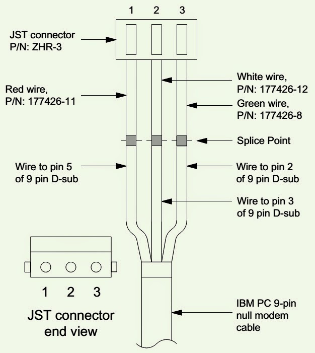
1 - JST 3 pin connector, JST model ZHR-3.
1 - Red wire with JST terminal, Bose part number 177426-11
1 - White wire with JST terminal, Bose part number 177426-12
1 - Green wire with JST terminal, Bose part number 177426-8
1 - B+B Electronics RS-232 to TTL converter, B+B model number 232LPTTL (available at the B+B Electronics web site.  Click this link to get it.)
* Cut off one end of the PC null modem cable. You will need only the three wires that correspond to pin 2, pin 3 and pin 5 of the 9 pin D-SUB connector.
* Mount the three wires with the pre-crimped JST terminals into the JST connector as shown.  The red wire goes to pin 1, the white to pin 2 and the green to pin 3.  Be sure to check that the wire locations are correct or your cable will not work.  Once the wires are installed, place a piece of heat shrink tubing over the three wires approximately 1/8" behind the JST connector and heat shrink it in place. This is to help keep the wires secured in the connector.  Now place a two inch long piece of heat shrink tubing over the other piece and just over the shoulder of the JST connector. Heats shrink this in place as well. This tubing will provide a convenient means of cable insertion and removal in the 3-2-1 console connector.
Tap Interface cable wiring diagram.
Console Region Code.
Note: You can only change the region code for a console a total of 4 times. After that the console will not change the region code.
* Connect the B+B RS-232 to TTL converter to one of the serial data ports on the back of your IBM compatible PC. Connect the TAP interface cable to the B+B converter. Plug the other end of the cable into J1 of the 3-2-1 console display board. This connector can be accessed from outside the cabinet, under the right side of the front of the console.
* Set up your computer as shown in the computer setup procedure earlier in this manual.
Power up the 3-2-1 system console. On the PC, open the terminal window that you have set up using the computer setup procedure. Open the connection between the PC and the console.
* On the console, place a DVD disc of the region that you want to change to into the console tray. For example, if you wanted to change a region code 1 console to region 2, you would place a region code 2 DVD disc into the console. Allow the disc to spin up.
* On the PC, type in the applicable TAP command from the table below and press ENTER on the keyboard. The region code will have changed to the new region.
REGION CODES & COMMANDS
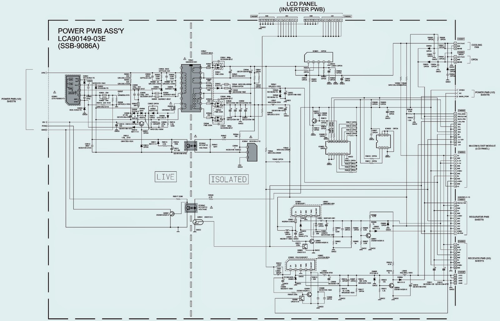
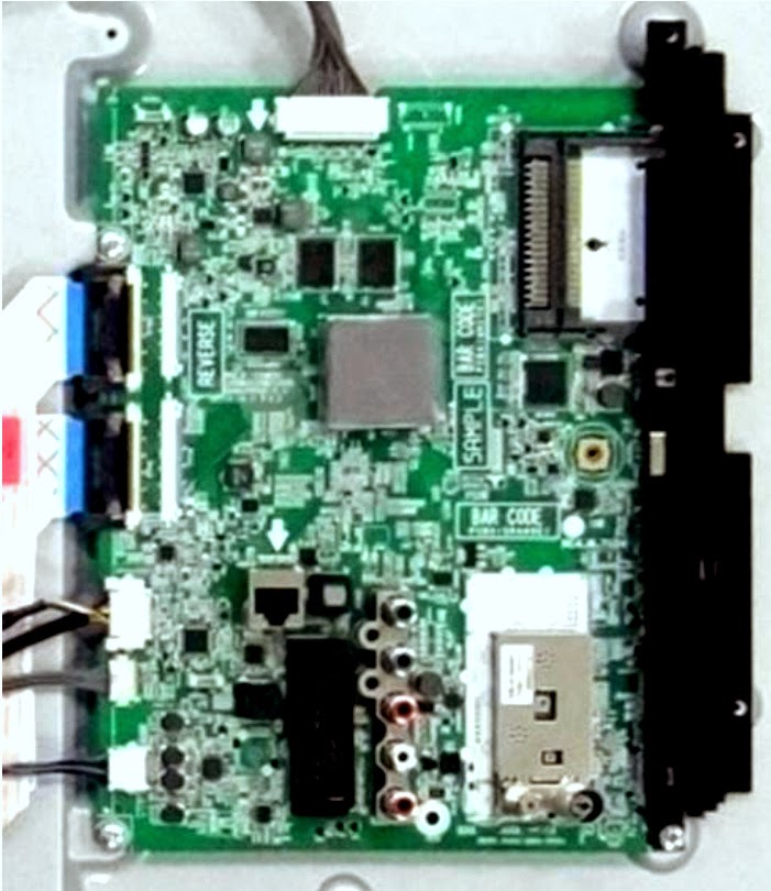
In case of circuit board defect; there is no repair to these; only card base replacement can be done, so there is no use to publish a schematic diagram here.  Power transformer is the only part that can be replaced.


SONY ICF-CD843V - HOW TO DISASSEMBLE - LASER PICKUP ASSEMBLY CHECK

$
0
0
SONY TV/WEATHER/FM/AM CD CLOCK RADIO _ ICF-CD843V_DISASSEMBLE_Optical Pickup Check Procedure.
LASER DIODE AND FOCUS SEARCH OPERATION CHECK
During normal operation of the equipment, emission of the laser diode is prohibited unless the upper lid is closed while turning ON the S302. (Push switch type)
The following checking method for the laser diode is operable.
Emission of the laser diode is visually checked.
* Open the upper lid.
** Push the S302 as shown in Fig.  Note: Do not push the detection lever strongly, or it may be bent or damaged.
*** Press the CD ►|| button.
Check the object lens for confirming normal emission of the laser diode. If not emitting, there is a trouble in the automatic power control circuit or the optical pick-up.  In this operation, the object lens will move up and down [2] times along with inward motion for the focus search.
REAR CABINET
CD LID
UPPER CABINET ASSY'
MAIN BOARD
CD BLOCK & OPTICAL PICKUP
CLICK ON THE PICTURES TO ZOOM IN

PHILIPS ACTIVE SUBWOOFER SW8000S - HOW TO DISASSEMBLE - Schematic Diagram

$
0
0
SPECIFICATIONS
Sub-woofer (not magnetically shielded design)....6.5"
Output Power...................................................100W (4 DIN)
THD (Total Harmonic Distortion) ........................10% at 55 Hz
Reproduction Frequency Response...................30 Hz-130 Hz
Phase Switch.....................................................0Deg,180Deg
Input Sensitivity (Subwoofer In).........................200 mVrms
AC Power (SW8000SA/01S).................................115/230V-60Hz/50Hz
AC Power (SW8000SA/17S).................................120V 60Hz
AC Power (SW8000SA/00S).................................230V 50Hz
Power Consumption...........................................66 W (at 1/8 Rated Power)
Dimensions (w x h x d)........................................195 mm x 460mm x 262mm
Weight...............................................................6.8 Kg
DISASSEMBLEY & SERVICE POSITION
SCHEMATIC
CLICK ON THE PICTURES TO ENLARGE

JVC LT26WX84/T – LCD FLAT TV – POWER SUPPLY REGULATOR SCHEMATIC

$
0
0
POWER SUPPLY CIRCUIT DIAGRAM_JVC LT-26WX84/T – LCD FLAT TV
POWER SUPPLY REGULATOR [SMPS] SCHEMATIC [Click on the pictures to Magnify]

HOW TO ENTER SERVICE MODE - JVC LT-26WX84/T

$
0
0
Service Mode Entry, Memory IC replacement & Adjustment Procedure
MEMORY IC REPLACEMENT
The memory IC stores data for proper operation of the video and deflection circuits.
When replacing, be sure to use an IC containing this (initial value) data.
MEMORY IC REPLACEMENT PROCEDURE
1. Power off.  Switch off the power and disconnect the power cord from the wall outlet.
2. Replace the memory IC.  Initial value must be entered into the new IC.
3. Power on.  Connect the power cord to the wall outlet and switch on the power.
4. SERVICE MODE setting
Before entering the SERVICE MODE, confirm that the setting of TV/CATV SW of the REMOTE CONTROL UNIT is at the "TV" side and the setting of VCR/DVD SW of the REMOTE CONTROL UNIT is at the "VCR" side. If the switches have not been properly set, you cannot enter the SERVICE MODE. 
A. Press [SLEEP TIMER] key and, while the indication of SLEEP TIMER 0 MIN is being displayed, press [DISPLAY] key and [VIDEO STATUS] key on the remote control unit simultaneously.
B.  The SERVICE MODE screen of Fig.1 is displayed.
C. Verify what to set in the SERVICE MODE, and set whatever is necessary.  Refer to the SERVICE ADJUSTMENT for setting.
D. Press the [BACK] key twice to return normal screen.
5. Receive channel setting
Refer to the OPERATING INSTRUCTIONS (USER'S GUIDE) and set the receive channels (Channels Preset) as described.
6.  User settings.
Check the user setting items according to after page. Where these do not agree, refer to the OPERATING INSTRUCTIONS (USER'S GUIDE) and set the items as Described.

SETTING ITEM NAME
Describe setting item name
SETTING VALUE
Set the setting value.
* Press [VOL+] / [VOL-] key. Set the setting value.
* Press [MUTING] key.  Memorize the data.
2. YC SEP (3D Y/C separation setting).  Sets output data to the 3D Y/C separation circuit.
Press [CH+] / [CH-] key: For scrolling up/down the item codes.
Press [VOL+] / [VOL-] key: For scrolling up/down the data values.
3. WHITE BALANCE (White balance setting) [Setting for this item is not required in servicing.]
4. MEMORY SETUP (Memory setting):  [Do not change settings]
5. RF AFC: Setting for this item is not required in servicing.
6. DD/CM: [Do not change settings]: Adjustment of color management and device driver.
7. PANEL (Panel power limit control): [Do not change settings]
8. PP (Multi-screen processing setting): [Do not change settings].  Sets output data to the multi-screen processing circuit.
# Press [CH+] / [CH-] key:  For scrolling up/down the item codes.
# Press [VOL+] / [VOL-] key:  For scrolling up/down the data values.
9. IP (DIST setting):  [Do not change settings]. Sets output data to the DIST circuit.
10. HDMI: [Do not change settings]:  Sets output data to the DIGITAL INPUT circuit.

HOW TO RE-TUNE BenQ FREVIEW TV or BOX.

$
0
0
When does switch-over happens?
Border >  Switched
West Country >  Switched
Granada >  Switched
Wales >  Switched
West >  Switched
STV North >  Switched
Channel Islands > Switched
STV Central >  Switched
Central > 2011
Yorkshire > 2011
Anglia > 2011
London >  2012
Meridian > 2012
Tyne Tees > 2012
UTV > 2012
* To find out which transmitter group you are likely to receive your TV signal from, visit the postcode checker at digitaluk.co.uk or call  on 08456 50 50 50
The digital TV switch over.
Television services in the UK are digital TV region by TV region, by 2012. The digital TV switch over is happening so that Freeview services (digital TV through an aerial) can be extended to people who can’t currently get them.

Digital UK is the not-for-profit organization responsible for leading the TV switch over. They’re independent, which means that all the advice and information  give is unbiased.
When to re-tune?
* At each of the two stages of switch over
* If at any time you find you have lost any TV channels
Regular re-tuning will ensure your equipment is up to date and that it picks up new channels as they become available.
How to re-tune Freeview TV or box?
1. Switch on the TV.
2. Press MENU and 1990 on your remote control.
3. An Initial Setup wizard is displayed. Press OK to continue.
4. Select your language, and press OK.
5. Select your country, and press OK.
6. Select Home mode, and press OK.
7. Select Analogue and Digital as your scan mode, and press OK.
8. Select Antenna as your tuner mode, and press OK.
9. Select Scan and press OK to start scanning for channels.
After re-tuning, press OK. You may have to reset your favorites list.
Re-tuning will take a few minutes.  Any Freeview product, including Freeview HD, needs to be re-tuned.

HOW TO ENTER SERVICE MODE - SONY MDS-JE530 - MINI DISC DECK Error Codes

$
0
0
SONY MDS JE530 _ US Model_Canadian Model_AEP Model_UK Model _ E Model & Singapore Model.
SPECIFICATIONS
Power requirements: North American model: 120 V AC, 60 Hz.  European model: 230 V AC, 50/60 Hz.  Other models: 110 – 120 V or 220 – 240 V AC, 50/60 Hz
Adjustable with voltage selector
Power consumption 16 W
Dimension (approx.) 430 ×95 ×280 mm (w/h/d) incl. projecting parts and controls.
Weight: (approx.) 3.4 kg.
SELF-DIAGNOSIS FUNCTION
  The self-diagnosis function consists of error codes for customers which are displayed automatically when errors occur, and error codes which show the error history in the test mode during servicing. For details on how to view error codes for the customer, refer to the following box in the instruction manual. For details on how to check error codes during servicing, refer to the following “Procedure for using the Self-Diagnosis Function (Error History Display Mode)”.
Fig error codes
PROCEDURE FOR USING THE SELF-DIAGNOSIS FUNCTION (ERROR HISTORY DISPLAY MODE)
Note: Perform the self-diagnosis function in the “error history display mode” in the test mode. The following describes the least required procedure. Be careful not to enter other modes by mistake. If you set other modes accidentally, press the MENU/NO button to exit the mode.
  1. While pressing the |◄◄ AM ►►|knob and POWER button, connect the power plug to the outlet, and release the |◄◄AMS ►►| knob and POWER button.
  2. Turn the |◄◄AMS ►►| knob and when [Service] is displayed, press the [YES] button.
  3. Turn the|◄◄AMS ►►| knob to display ERR DP MODE.
  4. Press the [YES] button to sets the error history mode and displays “total rec”
  5. Select the contents to be displayed or executed using the |◄◄ AMS ►►|knob.
  6. Press the |◄◄AMS ►►| knob to display or execute the contents selected.
  7. Press the|◄◄AMS ►►| knob another time returns to step 4.
  8. Press the [MENU/NO] button to display “ERROR DP MODE” and exits the error history mode.
  9. To exit the test mode, press the [REPEAT] button. The unit sets into the STANDBY state, the disc is ejected, and the test mode ends.
SELF DIAGNOSIS ITEMS & DESCRIPTIONS
ERROR CODES
CLICK ON THE PICTURES TO MAGNIFY

GENERAL 32GLED LCD TV - Power Supply - (SMPS) SCHEMATIC - TROUBLESHOOTING

$
0
0
Power supply (SMPS)_Troubleshooting & Schematic Diagram (Circuit Diagram -MP123T-24N )
SMPS TROUBLESHOOTING
POWER SUPPLY SCHEMATIC - MP123T-24N
CLICK ON THE PICTURES TO MAGNIFY


ADMIRAL - TELEFUNKEN - 21 INCH TV - CIRCUIT DIAGRAM - FULL

$
0
0
TDA9370 – MSP3420 – KA9260 – TDA3845 – TDA9859 – MSP3420 – STR-G5653 – TDA8943
CIRCUIT DIAGRAM [CLICK ON THE SCHEMATIC TO ZOOM IN]

SHARP 25RM100 CTV - HOW TO ENTER SERVICE MODE - SMPS and Horizontal Out Circuit Diagram

$
0
0
Sharp 25RM100N color TV - Service mode entry_Power supply and Horizontal Output Circuit Diagram. How to initialize the settings
SERVICE MODE
* Before putting unit into the service mode, check that customer adjustments are in the normal mode. Use the reset function in the video adjustment menu to ensure customer controls are in  their  proper (reset) position.
* Once in  the  service  mode, press  the  Ch-up / Ch down  button  on  the  remote  controller  or  at  the  set.  The service adjustment number will vary in increments of one, from "S01" to "OP2.
* Press the Vol-up / down button to adjust the data number.
To enter the service mode and exit service mode.
# While pressing the Vol-up and Ch-up buttons at the same time, plug the AC cord into a wall socket.  Now the TV set is switched on and enters the service
mode.
# To exit the service mode, turn the television off by pressing the power button.
RF AGC Adjustment
1. Receive a good local channel.
2. Enter the service mode and select the service adjustment "S08".
3. Set the data value to point where no noise or beat appears.
4. Select another channel to confirm that no noise or beat appears.
Note 1 : You will  have to come out of the service mode to select another channel.
Note 2: Setting the data to "00" will produce a black raster.
How to initialize the TV
Holding  down  both  the  Vol-up/CH-down  buttons  on  the  TV  set  at  service  mode  for  more  than  2  seconds  will automatically write the above initial values into IC2101.
SMPS (Power Supply Regulator) & H-OUT SCHEMATIC _ CLICK ON THE PICTURES TO MAGNIFY

HOW TO ENTER SERVICE MODE - SONY BLU-RAY PLAYER - BDP-BX18 _S185 _ S186

$
0
0
Initialize to Factory Settings
BDP-S185 _ Australian / NZ Model / Chinese Model / UK Model/ Russian Model.
BDP-S185 / S186_ AEP Model.
BDP-S185/BX18_ Canadian Model / US Model.
SERVICE MODE
OPTION 1
The set disconnect AC, and Push front panel key ([OPEN/CLOSE] + [PLAY] + [STOP]) and AC IN The keys will be released if the screen in service mode is displayed on a monitor.  Control via Remote Controller.
OPTION 2
Connect the set to AC, and wait initialization cycle complete. POWER ON SET INTO NORMAL MODE. WHEN CROSS MEDIA BAR APPEAR.
Use Sony BDP remote controller, key in the following SIRCS code.
[DISPLAY] => [ 0 ] => [ 2 ] => [ 1 ] => [SUBTITLE]
While sending of SIRCS code, wait time between each key code could not send later than 3 second.
If second waiting is exceeded user have to re-key in the SIRCS code.
If SIRCS enter is successful, set will auto boot up. The screen of service mode is displayed on a monitor.
Control via Remote Controller.
Diag
The unit test of the device mounted on the Main Board.
Display Error Log
Error log is displayed.  The displayed logs can be saved in a USB memory.
Factory Initialize
Return the entire player setting to their factory defaults.
Network
Confirm Wired Network connection.
Version Up
The set updates by Update DISC.
System Information
System information of the set is displayed.   The Information on a soft version and drive information, etc. is displayed.
EMC Test Mode
Not used.
Drive
Write Drive OP Data and check drive.
HDD Mode
Not used.
ERROR CODES
CLICK ON THE TABLE TO ZOOM IN
To initialize to factory settings
When set to the factory defaults, push [1] on this screen.
[ENT] Start   Factory Initialize
[R E T]   Ret urn to Service Top Menu.
Window 2
It is a screen of t he end of initialization.
[R E T]   Ret urn to Service Top Menu.
Disconnect AC power supply, and connect AC again.  - The operation of other service mode menu can be continued.

SONY BDP BX18 - S185 - S186 EXPLODED VIEW AND SPARE PART LIST

$
0
0
Exploded view: -XX  and  -X  mean standardized  parts,  so  they may  have  some  difference  from  the  original one.  Items marked “*” are not stocked since they are seldom required for routine service.
Abbreviation
AEP :  AEP Model
AR :  Argentina  Model
AUS :   Australia New Zealand Model
BR :   Brazilian  Model
CND : Canadian  Model
E :  Latin America Model
EA :  Middle East  Model
IN :  India Model
CN :  China  Model
US : USA Model
UK :  UK  Model
RUS :   Russian Model
Case section
Main chassis section
BD section
Accessories
Click on the pictures to Magnify

SONY KDL-40XBR4 - KDL-46XBR5 - SELF CHECK MODE- INVERTER REPLACEMENT - KDL-40XBR4 - KDL-46XBR5

$
0
0
KDL-40XBR4 - KDL-46XBR5 - KDL-40XBR5 - KDL-46XBR4 (Remote control RM-YD017)
Description of LED Indicators.
POWER LED > Green LED > Light when the TV set is on.
STANDBY LED > Red LED > Lights up in red when TV is in PC standby mode. If LED blinks continuously, this may indicate that the TV needs servicing.
PIC OFF/TIMER LED > Green or Orange LED > Lights up in green when Picture Off is activated.  Lights up in orange when the timer is set When timer is set, the LED remains lit even when the TV is turned off.
SELF DIAGNOSTIC FUNCTION
The units in this manual contain a self-diagnostic function. If an error occurs, the STANDBY LED automatically begins to flash. The number of times the LED fl ashes translates to a probable source of the problem. A definition of the STANDBY LED flash indicators is listed in the instruction manual for the user’s knowledge and reference. If an error symptom is difficult to reproduce use the Remote Commander to display the record that is stored at the internal NVM to specify the cause.
{One flash is not used for self-diagnosis}
Diagnostic Indicators
When an error occurs, the STANDBY LED flashes a set number of times to indicate the possible cause of the problem. If there is more than one error, the LED will identify the first of the problem areas. If the errors occur simultaneously, the one that corresponds to the fewest fl ashes is identified first. (Results for all of the following diagnostic items are displayed on screen. No error has occurred if the screen displays a “00”)
TV must be in standby mode. (Power off).
Press the following buttons on the Remote Commander within a second of each other:
DISPLAY> CHANNEL-5> VOLUME (--) > TV POWER.  The Self Check list displays.  Information Indicator displays time of last 3 events (Not used in FIX2 models).
Resetting the Diagnostic Indicators
After completing the repair of the set, reset the Self Check screen to set all the display results to “00”.
* TV must be in standby mode. (Power off).
* Press Display > Channel-5 > Volume (--) > TV Power
* Press Channel ‘8’ > then press channel ‘0’.  To EXIT, press TV Power.
REPLACING THE INVERTER CONNECTOR ASSEMBLY
1. After inserting the connector into the Inverter board, push the middle section of the inverter connector to lock on the terminal.
2. Push the right section of the inverter connector and confirm it is securely connected.
3. Push the left section of the inverter connector and confirm it is securely connected.

HOW TO REMOVE the INVERTER BOARD - SONY KDL-40XBR4_40XBR5_46XBR4_46XBR5

$
0
0
How to remove & replace the Inverter Board _ Sony KDL-40XBR4_40XBR5_46XBR4_46XBR5
MT INVERTER BOARD(S) REMOVAL
Be sure to identify the inverter cover screws before proceeding. 
DO NOT remove the screws securing the plastic strip holding the lamp sockets.
Remove screws securing the inverter cover.
Remove screws securing the inverter board.
REPLACING THE INVERTER CONNECTOR ASSEMBLY
After inserting the connector into the Inverter board, push the middle section of the inverter connector to lock on the terminal.
Push the right section of the inverter connector and confirm it is securely connected.
Push the left section of the inverter connector and confirm it is securely connected.

HOW TO ENTER SERVICE MODE AND MAKE ADJUSTMENTS TO SONY 40XBR5_46XBR4

$
0
0
ApplIcable to SONY -  KDL-40XBR4_ 40XBR5_46XBR4_46XBR5
ACCESSING SERVICE ADJUSTMENTS
To adjust various set features, use the Remote Commander to put the set into service mode to display the service menus.
TV should be in standby mode. (Power off).
Press the following buttons on the Remote Commander within a second of each other: Display > Channel (5) > Volume (+) > TV Power.
The first service menu (TV) displays.
To display the service menu that contains the category you want to adjust, press (JUMP) on the Remote Commander.
CLICK ON THE PICTURES TO ZOOM IN
The screen displays the first category in the selected service menu.
To change the category, press (2) or (5) on the Remote Commander.
Note: Pressing 2 or 5 only changes the categories within the service menu displayed. To change a category on one of the other service menus, press the {JUMP} button until the correct service menu is displayed.
To change the adjustment item, press (1) or (4) on the Remote Commander.
To change the data value, press (3) or (6) on the Remote Commander.
To write into memory, press {MUTING} then (0) on the Remote Commander.
To exit service mode, turn the power off.
UPDATING MODEL INFORMATION AFTER REPLACING THE FB1 BOARD.
Access the Service Menu (as described above)
Press the {JUMP} button until the BEM micro service menu displays.
Press (2) until the (0001 MODEL_INFO) category displays.
Using the (3) or (6) on the remote commander to increase or decrease the value, do one of the following:
[If model size is 40” > Set to (0)]
[If model size is 46” > Set to (1)]
To write into memory, press {MUTING} then (0) on the Remote Commander.
To exit service mode, turn the power off.


LG 42LA62** - 42LA62**-T* - 60LA62**-T - INTER CONNECTION DIAGRAM

$
0
0
LG 3-D - North/Latin America _ Europe/Africa _ Asia/Oceania _ Interconnection [Wiring]
60LA62 - SERIES
32LA62 - SERIES
LA64 - SERIES
Click on the pictures to Magnify

LG LCD TV-TROUBLESHOOTING - 42LA62** - 42LA62**-T*

$
0
0
LG 42LA62** - 42LA62**-T* _ North/Latin America _ Europe/Africa _ Asia/Oceania
Standard Repair Process:  Video error - No video/Normal audio - No video/ audio. - Video lag/stop. - Power supply regulator board-pin voltages.
You should have the “Adjust remote control” to do any change to data settings.  With user remote control, it is not possible to do it.  You can buy an adjust remote control from the authorized service center for LG.  It is advised not to adjust any data values; without knowing about what are you going to do.  Only proceed, if you’re confident about you can do it successfully.
ADJUST REMOTE CONTROL
NO VIDEO_NORMAL AUDIO
Entry method (To adjust parameters) : To check the White Balance value.
1. Press the ADJ button on the remote controller for adjustment.
2. Enter into White Balance of item 6.
3. After recording the R, G, B (GAIN, Cut) value of Color Temp (Cool/Medium/Warm), re-enter the value after replacing the MAIN BOARD.
NO VIDEO & AUDIO (In other-words, the set is dead, no Power LED glow at front panel)
Power Board fault.(Voltage measuring method_ Check the DC 24V, 12V, 3.5V.)
VIDEO ERROR (Video lag/stop)
TUNER input signal strength checking method:  MENU >  Support > Signal test > Select channel.
When the signal is strong, use the attenuator (-10dB, -15dB, -20dB etc.)
Checking method for remote controller for adjustment.
Press the IN-START with the remote controller for adjustment. [Version checking method]
Click on the pictures to Zoom In

LG LCD TV - 42LA62** - 42LA62**-T* - LA62** - 3D - TROUBLESHOOTING - COLOR ERROR

$
0
0
42LA62** - 42LA62**-T*
Europe/Africa _ Asia/Oceania_ North/Latin America.
Standard Repair Process: You should have the “Adjust remote control” to do any change to data settings.  With user remote control, it is not possible to do it.  You can buy an adjust remote control from the authorized service center for LG.  It is advised not to adjust any data values; without knowing about what are you going to do.  Only proceed, if you’re confident about you can do it successfully.
1. Video error _Vertical/Horizontal bar, residual image, Light-spot [Check the connections]
2. Video error _Video error, video lag/stop [Check the Tuner]
3. Color error _ [Adjustment Test pattern - ADJ Key]
1. Video error _Vertical/Horizontal bar, residual image, Light-spot [Check the connections]
As the part connecting to the external input, check the screen condition by signal.
2. Video error _Video error, video lag/stop [Check the Tuner]
Checking method:
1. Check the signal strength or check whether the screen is normal when the external device is connected.
2. After measuring each voltage from power supply, finally replace the MAIN BOARD.
3. Color error _ [Adjustment Test pattern - ADJ Key]
You can view 6 types of patterns using the ADJ Key
Checking item: 1) Defective pixel 2) Residual image 3) MODULE error (ADD-BAR, SCAN BAR..) 4)Video error (Classification of MODULE or Main-B/D)
CLICK ON THE PICTURES TO MAGNIFY

SCREEN-SHOTS OF DEFECTIVE LCD TVs – DEFECTS and SUSPECTED PARTS

$
0
0
DEFECTS and SUSPECTED PARTS – LG32LA64xx-T – LG42LA62xx-T – LG60LA62xx-T
Defective screen shots and possible causes.  These pictures can be taken as reference to most of the LED LCD TVs, irrespective of its Brand and Model.
EPI Cable or Main B/D fault-1  (Click on the pictures to Magnify)
EPI Cable or Main B/D fault-2
LPB (LED driver) fault
Exchange the Module [Un-repairable cases]

VCOM and FLICKER ADJUSTMENT - LG 42LA62xx _ LG42LA62xx-T LCD TV

$
0
0
LG 42LA62xx _ LG42LA62xx-T North/Latin America, Europe/Africa, Asia/Oceania (CHASSIS : LB33B)
HOW TO ADJUST V- COM, FLICKER _ No response to remote control.
No response in remote controller, key error, VCOM Adjustment (Flicker)
Remote controller operation checking method.
1, 2. Check IR cable condition between IR & Main board.
3. Check the St-by 3.5V on the terminal 4.
4. When checking the Pre-Amp when the power is in ON condition, it is normal when the Analog Tester needle moves slowly, and defective when it does not move at all.
VCOM Adjustment.  Sequence of the V-com adjustment.
Case
LCD module change.
T-Con board change.
Equipment
Service Remote controller.
Adjust sequence
* Press the ‘adj’ key
* Select V-COM
* As pushing the right or the left button on the remote controller, and find the V-COM value which is no or minimized the Flicker(If there is no flicker at default value, Press the exit key and finish the VCOM adjustment.)
Push the OK key to store the value. Then the message “Saving OK” is pop.
Press the exit key to finish V-COM adjustment.
Service (Adjust) Remote Control
CLICK ON THE PICTURES TO ZOOM IN

Viewing all 2033 articles
Browse latest View live


<script src="https://jsc.adskeeper.com/r/s/rssing.com.1596347.js" async> </script>