Quantcast
Channel: Electro help
Viewing all 2033 articles
Browse latest View live

HOW TO CHECK Dimming Function - Wi-Fi, Magic Motion Remote control and 3D - LG42LA6200

$
0
0
LG42LA6200_ Dimming Function - Wi-Fi,  Magic Motion Remote control & 3D function Checks.
LOCAL DIMMING FUNCTION CHECK
* Turn on TV.
* At the Local Dimming mode, module Edge Backlight moving right to left Back light of IOP module moving.
* Confirm the Local Dimming mode.
* Press "Exit" key.
Magic Motion Remote control test
Equipment:  RF Remote control for test, IR-KEY-Code Remocon for test.
You must confirm the battery power of RF-Remote control before test (recommend that change the battery per every lot).
Sequence (test)
* If you select the ‘start key(Wheel Key)’ on the controller, you can pairing with the TV SET.
* You can check the cursor on the TV Screen, when select the ‘Wheel Key’ on the controller.
* You must remove the pairing with the TV Set by select ‘Mute Key’ on the controller.
3D function test
(Pattern Generator MSHG-600, MSPG-6100[Support HDMI1.4])
* HDMI mode NO. 872 , pattern No.83
  1. Input 3D test pattern like below.
  2. When 3D OSD appear automatically, then select OK key.
  Don't wear a 3D Glasses, check the picture like below.
Wi-Fi Test
* Turn on TV
* Select Network Connection option in Network Menu.
* Select Start Connection button in Network Connection.
If the system finds any AP like blow PIC, it is working well.
CLICK ON THE PICTURES TO MAGNIFY


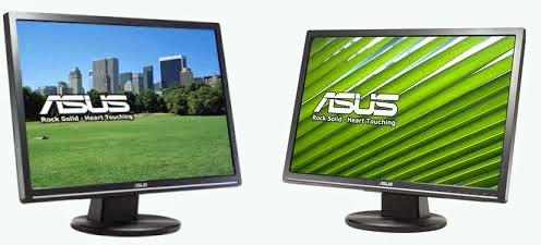
ASUS VW-223 - LCD MONITOR - POWER SUPPLY and INVERTER SCHEMATIC

$
0
0
Asus VW-223 LCD monitor_Power Supply & Back-light Inverter _ Circuit Diagram.
Click on the Pictures to Zoom In
SMPS SCHEMATIC
INVERTER SCHEMATIC

HOW TO DISASSEMBLE - ASUS G1S Series Notebook

$
0
0
Disassembley Procedure to ASUS G1S Series Notebook - Memory module removal
* Remove the battery module.
* Slide the battery latch 1 to open battery lock
* Slide the battery latch 2 and pull the whole battery away from the system.
* Remove 2 screws (M2*4) and take the CPU door away.
* Remove the Mylar.
* Remove 4 screws (M2*5) aside the CPU. And take away the heat sink.
* Turn the non-removable screw here 180 degrees counter-clockwise to loosen the CPU.
Removing Memory module
* Remove 2 screws on the memory cover and then remove the cover.
* Unlock two latches to pop up the memory at 45 angles then pull out the memory at that angle.

KENWOOD - LG - KDV-MP4339 DVD Receiver - HOW TO UPGRADE THE MAIN FIRMWARE

$
0
0
How to upgrade the main Firmware to Kenwood /LG DVD Receiver_KDV-MP4339/MP4439/KDV-MP5032/3241Y
SPECIFICATIONS
(KDV-MP4339/MP4439/MP5032)
Maximum output power: 50 W x 4
Full Bandwidth Power (at less than 1% THD) : 25 W x 4
Speaker Impedance: 4 – 8 Ω
Tone action
Bass: 100 Hz ±8 dB
Middle: 1 kHz ±8 dB
Treble: 10 kHz ±8 dB
Pre out level / Load (CD) : 4000 mV/47 kΩ
Pre out impedance: ≤ 600 Ω
(KDV-3241Y)
Maximum output power : 50 W x 4
Output power (DIN 45324, +B=14.4V) : 30 W x 4
Speaker Impedance: 4 – 8 Ω
Tone action
Bass: 100 Hz ±8 dB
Middle: 1 kHz ±8 dB
Treble: 10 kHz ±8 dB
Pre out level / Load (CD) : 4000 mV/47 kΩ
Pre out impedance: ≤ 600 Ω
MAIN FIRMWARE UPGRADE
 Caution:If power is off on the way of upgrading firmware, the set can’t be recovered.  Therefore pay lots of attention for power not to be off.
Confirmation of version information
* Change the Source of audio set to CD/DVD. (Default: tuner)
* Turn power off using power key.
* Press power key for 5 sec. (After power on, continue pressing)
* After 5 sec, beep sound rings two times.  Then version information would show up at display.
* In order to check version of MAIN/CD system, Press band key.
* The version of system for main & CD is displayed in sequence.
Upgrade Program reading
Insert update CD in ACC on state and then [READING> M_UPGRAD] is displayed in order.
Upgrade start
In order to start upgrade, Press 1 [ENTER] key.
Upgrade progress display
Upgrade is in progress now.
[Erase > Write > I-VRF > D-VRF]
Upgrade Completion.
When Upgrade finished, the display shows up “DOWN OK”. After 3 seconds, the audio set is reset automatically.

HOW TO UPGRADE DVD FIRMWARE_KENWOOD KDV-MP4339 - MP4439 - KDV-MP5032/3241

$
0
0
Kenwood / LG - DVD FIRMWARE UPGRADE METHOD _ HOW TO CONNECT AUDIO SET TO POWER SUPPLY_ KDV-MP4339 - MP4439 - KDV-MP5032/3241
Upgrade Program reading
Insert update CD in ACC on state and then [READING > D_UPGRAD] is displayed in order.
Upgrade start
In order to start upgrade, Press 1[ENTER] key.
Upgrade progress display
Upgrade is in progress now. [Read > Erase > Write > Verify]
Upgrade Completion
When Upgrade finished, the DVD module is reset automatically.
TO CONNECT AUDIO SET TO POWER SUPPLY
It is sufficient only to supply power for upgrade.
Shown from the right figure, connect yellow line (Battery) and red line (Ignition) to plus and minus terminal respectively.
Jack is connected to the audio set via its shapes matched each other.
We need power supply for operation of audio set (Voltage : 12~15V Current : Over 2A) Before connection between set and power supply, adjust voltage level to 15V typically (It is okay up to 12V.)
Power Supply has a variety of shapes and capacity of voltage and current. At first check these things.

LG LAB5900N - CAR CD/MP3/WMA RECEIVER - SCHEMATIC DIAGRAM

$
0
0
CAR CD/MP3/WMA RECEIVER_LG LAB5900N_SCHEMATIC (Circuit Diagram).
CLICK ON THE SCHEMATICS TO MAGNIFY

MAIN BOARD [HA13173_TB2926HQ_UPD78F1164]
FRONT CONTROL
CDP-1
I-POD

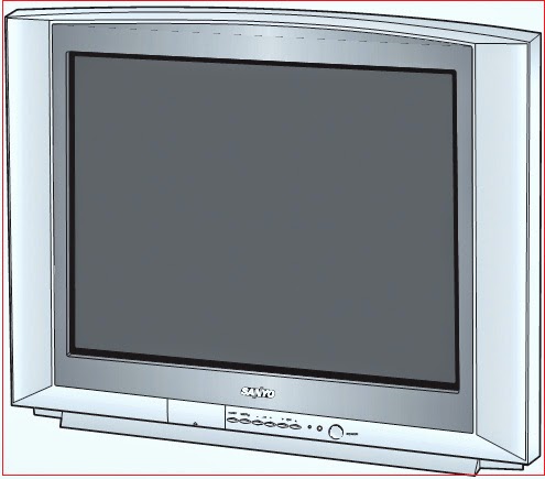
SANYO CE29EF1 - HOW TO ENTER SERVICE MODE - INITIALIZATION

$
0
0
Memory IC Initialization (after replacement)_Service Mode _ SANYO CE29EF1 CTV
Initializing Procedure
* Replace a new memory IC.
* Turn on the TV set.
* Press and hold the TV/AV Selector on the TV set for more than 2 seconds.
* Press the PROGRAMME Upon the TV set while the above On-Screen Display is still on the screen. The following pictures appear on the screen.
This completes the initialization of memory IC.
Following shows the initialized contents of memory data by this procedure.
Plug & Play : No executed
Inhibit Data : Cancelled
Ch Skip Data : Cancelled
Sound Volume Data : 10/63 steps.
Volume Lock  : OFF
Tuning Lock : OFF
Music Mode : OFF
AV Start : OFF
Color System : AUTO
Required Service Adjustments:
Readjust the following service adjustments.
Adjustments Service Mode No. & Item
RF AGC Item 01 > RF AGC
Horizontal centre Item 02 > H-PHA
Vertical size Item 05 > V-SIZE
Vertical linearity Item 06 > V-LIN
Vertical S-Correction Item 07 > V-SCO
Gray scale Item 30-33, 35-37
Entering to Service Mode
* Press and hold the MENU button on the Remote Control and press the VOLUME (+) button on the TV set.  Following setting items appears on the screen.
* Select item by pressing the TIMER (Item No. UP) or SOUND MUTE (Item No. DOWN) button on the remote control handset.
* Adjust data value by pressing the VOLUME +or VOLUME -button on the remote control handset.
Click on the pictures to Magnify
To return to normal TV mode, press the MENU button on the TV set or the remote control handset.

SONY KDL KDL-40Z4500 - KDL-46Z4500 - LED BLINKING CODES (ERROR CODES)

$
0
0
Sony LCD TV KDL-40Z4500 - KDL-46Z4500 - KDL-52Z4500_SELF DIAGNOSIS FUNCTION_LED blinking codes.
SELF DIAGNOSIS FUNCTION
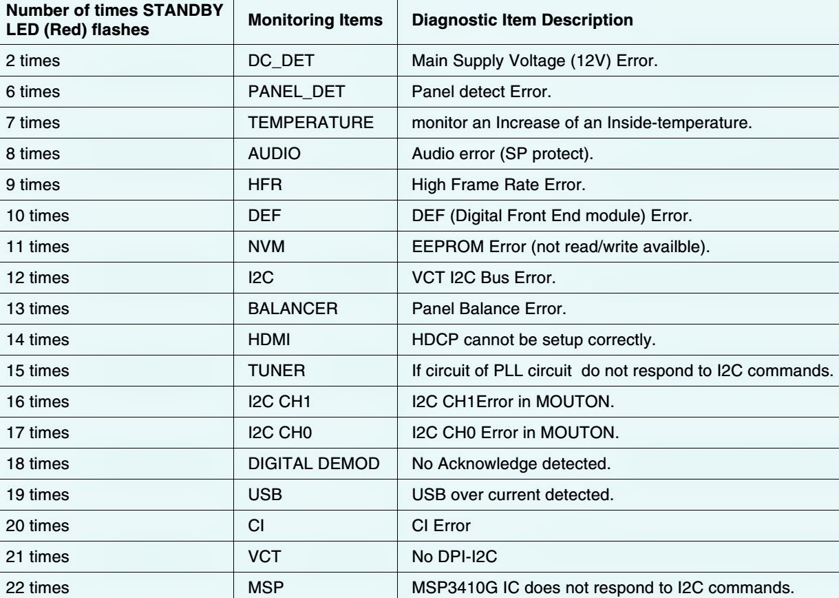
The units in this manual contain a self-diagnostic function. If an error occurs, the STANDBY LED will automatically begin to flash.  The number of times the LED flashes translates to a probable source of the problem.  A definition of the STANDBY LED flash indicators is listed in the instruction manual for the user’s knowledge and reference.  If an error symptom cannot be reproduced, the remote commander can be used to review the failure occurrence data stored in memory to reveal past problems and how often these problems occur.
DIAGNOSTIC TEST INDICATORS

When an error occurs, the STANDBY LED will flash a set number of times to indicate the possible cause of the problem.  If there is more than one error, the LED will identify the first of the problem areas.  Result for all of the following diagnostic items is displayed on screen.  If the screen displays a “0”, no error has occurred.
BLINKING CODES
DISPLAY OF STANDBY LIGHT FLASH COUNT & STOPPING THE STANDBY FLASH
Turn off the power switch on the TV main unit or unplug the power cord from the outlet to stop the STANDBY LED for flashing.
SELF-DIAGNOSTIC SCREEN DISPLAY
For errors with symptoms such as “power sometimes shuts off” or “screen sometimes goes out” that cannot be confirmed, it is possible to bring up past occurrences of failure for confirmation on the screen:
To Bring Up Screen Test
In standby mode, press buttons on the remote commander sequentially in rapid succession as shown below:  Note that this differes from entering the service mode (Volume + )
Press buttons on the remote control in this series [INFO > NUMBER BUTTON (5) > VOLUME (-ve) > TV STANDBY].
SELF-DIAGNOSTIC SCREEN DISPLAY
Since the diagnostic results displayed on the screen are not automatically cleared, always check the self-diagnostic screen After you have completed the repairs, clear the result display to “0”
Clearing the result display
To clear the result display to “0”, press button on the remote commander sequentially as shown below when the diagnostic screen is being displayed.
Deletion of Error Count and Error History
Press (8) button > Press (0) button.
Deletion of Panel Operation Time
Press (7) button > Press (0) button
Quitting Self-diagnostic screen
To quit the entire self-diagnostic screen, turn off the power switch on the remote commander or the main unit.


ERROR CODES (Blinking Codes) DETAILS - SONY KDL-40Z4500 - KDL-46Z4500 - KDL-52Z4500

$
0
0
Blinking codes details & Suspected circuit boards.  Be sure to contact any service technician too, to confirm the fault.  These details are indications only. SONY_ KDL-40Z4500 - KDL-46Z4500 - KDL-52Z4500
DIAGNOSTIC TEST INDICATORS
When an error occurs, the STANDBY LED will flash a set number of times to indicate the possible cause of the problem.  If there is more than one error, the LED will identify the first of the problem areas.  Result for all of the following diagnostic items is displayed on screen.  If the screen displays a “0”, no error has occurred.
ERROR CODES & DETAILS
DC_DET:  [RED 2 times blinks]
This indicates DC_DET of Power Board.
12V line on Power Board.
MOUTON micro (on BGC board) Pin6 detects POWER_DET and shuts down chassis power to standby status.
MOUTON micro Pin6 Normal condition: 1.3V - 2.5V.
Error case: lower than 1.3V or higher than 2.5V
Replace Power Board.
Backlight Error [RED 6 times blink]
This indicates panel power circuit error such as inverter.
MOUTON micro (on BGC board) Pin40 detects PANEL_DET and shuts down chassis power to standby status.
MOUTON micro Pin40 Normal condition: High / Error case: Low (lower than 0.8V)
Replace Panel or Power/Inverter Board.
Temp Error [RED 7 times blink]
This indicates high temperature inside chassis.
IC5507 on BGC board is monitoring temperature.   IC5507 is controlled by MOUTON micro.
When it happens:
Check chassis environment.
Check around IC5507 and replace BGC board if temperature monitoring circuit  has problem.
Check panel.
Audio Error [RED 8 times blink]
This indicates Audio Error (Protection).   It happens:
IC8200 on BGC board, Audio Amp detects over current, thermal shut down  and/or low voltage of itself.
DC voltage detected for audio line.
MOUTON micro Pin5 Normal condition: High / Error case: Low
Check UNREG15V at CN6401 Pin4 and Pin5 on BGC board And F3401 on BGC board has 13V or not.
Check above and replace BGC board.
HFR Error [RED 9 times blink]
This indicates HFR Communication error.
[ HFR Communication error ]
Mouton (IC5505) micro (on BGC board) is communicating with T-con board.
Check above and replace BGC board or LVDS harness (between BGC board and T-con board).
DEF Error [RED 10 times blink]
This indicates DEF communication error.   [communication error ]
TVM micro (on BGC board) is communicating with EMMA3SL (on BGC board).
Check above and replace BGC board.
NVM Error RED 11 times blink
This indicates MOUTON NVM communication error. 
MOUTON micro (on BGC board) is communicating with NVM (on BGC board) 
Check above and replace BGC board.
I2C Error [RED 12 times blink]
This indicates I2C communication error.
VCTP micro (on BGC board) is communicating with each devices (on BGC board).
Check above and replace BGC board.
Balancer Error [RED 13 times blink]
This indicates panel power circuit error such as inverter.
MOUTON micro (on BGC board) Pin81 detects PANEL_DET and shuts down chassis power to Standby status.
MOUTON micro Pin40 Normal condition: High / Error case: Mid (0.85 - 2.65V)
Replace Panel or Power/Inverter board.
HDMI Error RED 14 times blink
This indicates HDCP error.
HDMI setting trouble matter on BGC board.
Check above and replace BGC board.
Tuner Error [RED 15 times blink]
This indicates Tuner error.
VCTP and EMMA3SL micro (on BGC board) is communicating with Tuner (TU2200) on BGC board.
Check above and replace BGC board.
I2C-CH1 Error [RED 16 times blink]
This indicates I2C communication error.
MOUTON micro (on BGC board) is communicating with Audio processor (IC3201) on BGC board.
Check above and replace BGC board.
I2C-CH0 Error [RED 17 times blink]
This indicates I2C communication error.
MOUTON micro (on BGC board) is communicating with Real time clock (IC5502) on BGC board.
Check above and replace BGC board.
Digital modulator Error [RED 18 times blink]
This indicates Tuner error.
EMMA3SL micro is communicating with inside of the Tuner (TU2200) on BGC board.
Check above and replace BGC board.
USB Error [RED 19 times blink]
This indicates USB error.
EMMA3SL micro found out USB over current detection on BGC board.
Check above and replace BGC board.
VCTP Error [RED 21 times blink]
This indicates VCTP error. 
VCTP micro (IC4701) does not work normally. 
Check above and replace BGC board.
KDL-40Z4500 {[BOARD LAYOUT] (BACK VIEW)}
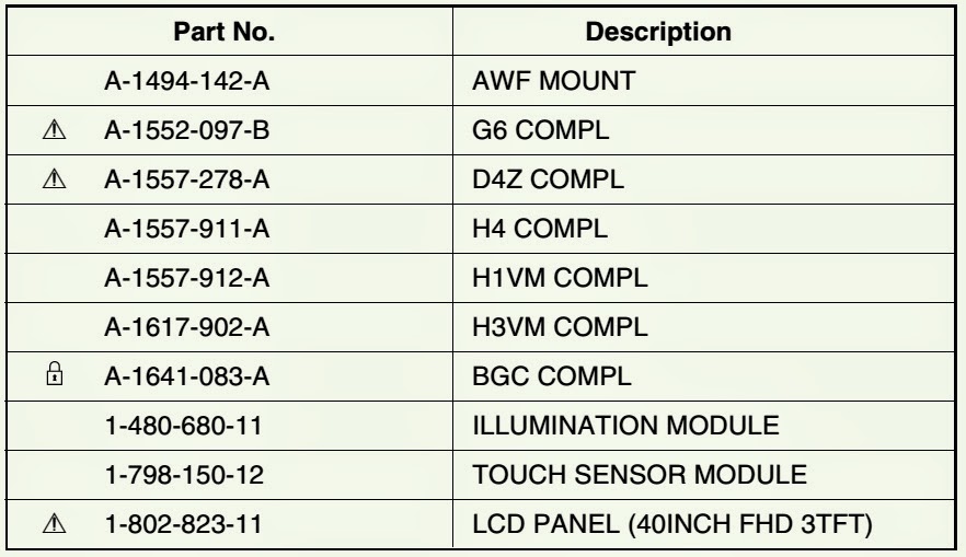
KDL-46Z4500 (Part numbers)
KDL-52Z4500 (Part numbers)
CLICK ON THE PICTURES TO ZOOM IN
To know more,  see the previous post here.

HP COLOR LASER-JET CLEANING PROCEDURE- 8500 – 8550 Printer Family

$
0
0
Cleaning procedure that user can do.
CLEANING POST CHARGER
Clean the post charger on the transfer drum if there are light streaks in halftone areas.
To clean the post charger
1 Open the right upper door.
2 Locate the post charger unit cleaner next to the transfer drum handle.
3 Slide the post charger unit cleaner across the bar several times.
4 Push the cleaner back into place.
5 Close the right upper door.
Cleaning the density sensor
Clean the density sensor after replacing the imaging drum and when printed colors are inaccurate.
To clean the density sensor and erase lamp.
1 Open the right upper door.
2 On the inside of the door, locate the density sensor and the density sensor brush. Use the brush to brush off toner particles from the density sensor and the erase lamp.  Note:  You can also use a hand wipe to clean the density sensor. To prevent scratches on the sensor, do not use any paper products, such as tissue or paper towels, to clean the sensor.
3 Replace the brush.
4 Close the right upper door.
Cleaning the transfer charger
Clean the transfer charger when irregular wavy patterns appear in solid backgrounds.
To clean the transfer charger
1 Open the front door.
2 Find the knob below the transfer charger.
3 Pull the knob out and push it back in.
4 Close the front door.
Cleaning the toner catch tray
The toner catch tray will not normally have much toner in it. Clean the toner catch tray before moving the printer to another location or when performing routine maintenance at the customer site.
1 Open the front door.
2 Remove the toner catch tray cover by releasing the tab on the right side of the cover with a small screwdriver.
3 Remove the toner catch tray.
4 Vacuum toner out of the tray, or use a hand wipe to clean the tray if there is a small amount of toner in the tray.
WARNING:  Do not use a regular vacuum to clean up toner. The toner can penetrate the vacuum bag, and toner might be harmful if inhaled.
5 Re-install the toner catch tray and cover, and close the front door.
Cleaning the toner catch tray
The toner catch tray will not normally have much toner in it. Clean the toner catch tray before moving the printer to another location or when performing routine maintenance at the customer site.
1 Open the front door.
2 Remove the toner catch tray cover by releasing the tab on the right side of the cover with a small screwdriver.
3 Remove the toner catch tray.
4 Vacuum toner out of the tray, or use a hand wipe to clean the tray if there is a small amount of toner in the tray.
WARNING:  Do not use a regular vacuum to clean up toner. The toner can penetrate the vacuum bag, and toner might be harmful if inhaled.
5 Reinstall the toner catch tray and cover, and close the front door.

HOW TO ENTER SERVICE MODE - HP Color Laser-jet 8500/8550 - PRINTER

$
0
0
HP Color LaserJet 8500/8550_Service Mode & Adjustments
SERVICE MODE MENU
The Service Mode Menu can be entered only by pressing the left side of the ITEM and the VALUE keys at the same time.  
NVRAM SETTING (nonvolatile random-access memory setting) menu is provided to replace values that might be lost when a formatter board or control board is replaced in the field.
FORMATTER DIAGNOSTICS menu is provided for manufacturing and field service personnel to perform specific diagnostic tests on the formatter board and its related components.
* Service personnel can pinpoint problem areas on the formatter board for replacement or for tracking defects.
* The operator can choose which tests are enabled and disabled during execution, whether the tests run once or continuously, and whether the test sequence stops upon failure or continues despite failure.
* A fault log is implemented within formatter diagnostics to record errors for review.
* Because many of the formatter diagnostic tests are destructive memory tests, a special key sequence is used to enter the mode. A message warns service personnel that the printer is about to perform destructive memory tests.
CLICK ON THE TABLES TO ZOOM IN

ERROR CODES HP Color Laser-jet 8500/8550 - PRINTER

$
0
0
Color Laser-jet 8500/8550 _ Error code display & Details
PRINTER ERROR CYCLE POWER: Event log message: 55.00.01
Description:
Indicates a printer command error. The commands cannot be exchanged between the printer and its controller.
Action:
1 Turn the printer off and on to reset the printer.
2 Verify the controller board is fully seated.
ERROR CYCLE POWER: Event log message: 56.01.01
Description:
Indicates an input feed error (such as requesting to feed transparencies through the duplexer), or that the input tray is not installed.
Action:
1 If the input tray you are trying to print from is not installed, install the input tray.
2 Turn the printer off and on to reset the printer.
ERROR CYCLE POWER: Event log message: 56.00.02
Description:
Indicates an illegal output error. For example, the multi-bin mailbox is not installed and it was selected as the output destination, or there are transparencies in the duplexer.
Action:
1 Open the printer and remove media from the paper path.
2 Verify that the media type is set in the printer control panel.
3 Turn the printer off and on to reset the printer.
FAN FAILURE: Event log message: 57.00.01
Description:
One of the cooling fans failed or is obstructed.
1 = Fan 1 (FM 1)
Action:
Caution: Turn the printer off and do not operate the printer in this condition or it can be seriously damaged.
1 Turn the printer off and on to reset it.
2 Reconnect connectors J702 and J706 on the carousel motor PCA, and connector J220 on the controller board.
3 Reconnect connector J701 on the carousel motor PCA, connectors J648 and J641 on the main relay PCA, and connector J102 on the DC power supply.
4 Measure the voltage across J702-3 (FAN1ON) and J701-2 (GND) on the carousel motor PCA after the printer is turned on. If the voltage changes from 0 V to 24 V, replace fan 1.
5 Measure the voltage across connector J701-1 (+24 VB) and J701-2 (GND) on the carousel motor PCA after the printer is turned on. If the voltage is about 24 V, replace the carousel motor.
6 Measure the voltage across connector J641-1 (+24 VB) and J641-4 (GND) on the main relay PCA after the printer is turned on. If the voltage is not 24 V, replace the main relay PCA.
7 Check the AC power supply.
8 If the problem is not rectified after the printer is turned off and on again, find the cause of activation of the over current/overvoltage detection circuit in the power supply. Wait more than two minutes before turning the power back on.
9 Replace the power supply.
FAN FAILURE: Event log message: 57.00.02
Description:
One of the cooling fans failed or is obstructed.
2 = Fan 2 (FM 2)
Action:
Caution: Turn the printer off and do not operate the printer in this condition or it can be seriously damaged.
1 Turn the printer off and on to reset it.
2 Reconnect connectors J703 and J706 on the carousel motor PCA and connector J220 on the controller board.
3 Reconnect connector J701 on the carousel motor PCA, connector J648 on the main relay PCA, and connector J102 on the DC power supply.
4 Measure the voltage across connector J703-3 (FAN2ON) and J703-1 (GND) on the carousel motor PCA after the printer is turned on. If the voltage changes from 0 V to 24 V, replace fan 2.
5 Measure the voltage across connector J701-1 (+24 VB) and J701-2 (GND) on the carousel motor PCA after the printer is turned on. If the voltage is about 24 V, replace the carousel motor.
6 Measure the voltage across connector J641-1 (+24 VB) and J641-4 (GND) on the main relay PCA after the printer is turned on. If the voltage is 24 V, replace the main relay PCA.
7 Check the AC power supply.
8 If the problem is not rectified after the printer is turned off and on again, find the cause of activation of the over current/overvoltage detection circuit in the power supply. Wait more than two minutes before turning the printer back on.
9 Replace the power supply.
FAN FAILURE: Event log message:57.00.03
Description:
One of the cooling fans failed.
3 = Fan 3 (FM 3)
Action:
Caution: Turn the printer off and do not operate the printer in this condition or it can be seriously damaged.
1 Turn the printer off and on to reset it.
2 Reconnect connectors J645 and J647 on the main relay PCA, J18 and J74 relay connectors, and connector J227 on the controller board.
3 Reconnect connector J641 on the main relay PCA, and connector J102 on the power supply.
4 Measure the voltage across J645-3 (FAN3ON) and J645-1 (GND) on the main relay PCA after the printer is turned on. If the voltage changes from 0 V to 24 V, replace fan 3.
5 Measure the voltage across connector J641-1 (+24 VB) and J641-4 (GND) on the main relay PCA after the printer is turned on. If the voltage is not 24 V, replace the main relay PCA.
6 Measure the voltage across connector J641-1 (-24 VB) and J641-4 (GND) on the main relay PCA after the printer is turned on. If the voltage is not 24 V, replace the main relay PCA.
7 Check the AC power supply.
8 If the problem is not rectified after the printer is turned off and on again, find the cause of activation of the over current/overvoltage detection circuit in the power supply. Wait more than two minutes before turning the printer back on.
9 Replace the controller board.
ERROR CYCLE POWER: Event log message:58.00.01
Description:
Indicates that the paper diverter inside the right upper door is out of position, causing an error feeding media from tray 1.
Action:
1 Open the right upper door and check for a media jam or mis fed media.
2 Turn the printer off and on to reset the printer.
MOTOR ERROR CYCLE POWER: Event log message:59.00.0 <x>
Description:
Indicates that the main motor (M4) is not working properly.
<x> = Description:
0 = General error
1 = Startup error
2 = Rotation error
Action:
1 Turn the printer off and on to reset the printer.
2 Reconnect connector J219 and relay connector J1 on the controller board.
3 Replace the main motor (M4).
4 Reconnect connectors J641 to J643 and J647 on the main relay PCA, connectors J671 and J673 on the sub relay PCA, connector J102 on the power supply, and connector J227 on the controller board.
5 Check electrical continuity between connector J641-1 (+24 VB) and J642-3 (PMP) on the main relay PCA when the door switch (SW641) is turned on. If there is no electrical continuity, replace the main relay PCA.
6 Check electrical continuity between connector J671-2 (PMP) and J671-2 (PFUPR) on the sub relay PCA when the door switch (SW671) is turned on. If there is no electrical continuity, replace the sub relay PCA.
7 Measure the voltage across connector J647-B11 (+24 UH) and J647-4 (GND) on the main relay PCA after the printer is turned on. If the voltage is not 24 V, replace the main relay PCA.
8 Replace the controller board.
SERVICE CYCLE POWER: Event log message: 62.00.0 <x>
Description:
Indicates that a problem exists with the internal memory.
<x> = Description:
0 = Internal ROM or RAM
1-8 = DIMM slots 1-8
Action:
1 Turn the printer off and on to reset the printer.
2 Perform DRAM DIMM test from the formatter diagnostics in the Service Menu.
3 If the problem persists, replace the bad DIMM.
SERVICE CYCLE POWER: Event log message: 63.00.00
Description:
Indicates that the internal RAM memory test failed.
Action:
1 Turn the printer off and on to reset the printer.
2 Perform DRAM DIMM test from the formatter diagnostics in the Service Menu.
3 If the problem persists, replace the bad DIMM.
Entering the Service Mode Menu
1 From a READY state, press MENU until SERVICE MENU
appears.
2 Press ITEM – (the left side of the key) and VALUE –simultaneously. until SERVICE MENU appears.

HP-8500 - HP8550 - COLOR LASER PRINTER - TROUBLESHOOT - PRINT FAULTS

$
0
0
Faults occurs due to defects of Transfer belt- Fuser- Transfer drum- Transfer roller- Charging roller
Repetitive defects troubleshooting
Repetitive defects are defects that occur in the same vertical position on the page, but not necessarily on every page. Most repetitive defects are caused by problems with one of the following, and are indicated by the positioning of the defect on the page:
Developer roller (at 38 mm)
Charging roller (at 44 mm)
Cleaning roller (at 56 mm)
Developer DSD wheels (at 65 mm)
Transfer roller (at 66 mm)
Transfer drum (occurs once per 11-by-17 inch or A3-sized page, or every other letter- or A4-sized page)
Fuser (at 150.5 mm)
Imaging drum (at 195 mm)
Transfer belt (at 222 mm)
Color developer roller
Symptoms: Print defect occurring every 38 mm.
Cause: Dirty or damaged developer roller.
Actions: Replace the toner cartridge.
Charging roller
Symptoms: Print defect occurring every 44 mm.
Cause: Dirty or damaged charging roller.
Actions: Replace the imaging drum.
Black developer roller
Symptoms: Print defect occurring every 38 mm.
Cause: Dirty or damaged developer roller.
Actions: Replace the toner cartridge.
Cleaning roller
Symptoms: Print defects occurring every 56 mm.
Cause: Dirty or damaged cleaning roller.
Actions: Clean the cleaning roller with a hand wipe. If cleaning does not resolve the defect, replace the cleaning roller.
Developer DSD wheels
Symptoms: Print defect occurring every 65 mm.
Cause: Dirty or damaged developer DSD wheels. These wheels are located on the outer ends of the color toner cartridge and appear as a black bushing.
Actions: Replace the toner cartridge of the color producing the repetitive defect.
Transfer roller
Symptoms: Print defect occurring every 66 mm.
Cause: Dirty or damaged transfer roller.
Actions: Clean the transfer roller with isopropyl alcohol and a hand wipe. If cleaning does not resolve the defect, replace the transfer belt.
Transfer drum
Symptoms: Print defect occurring once per page on 11-by-17-inch-or A3-sized media, or on every other letter- or A4- sized page.
Cause: Dirty or damaged transfer drum.
Actions: Clean the transfer drums (see below). If the defect is not resolved by cleaning, replace the transfer drum.
Cleaning the transfer drum
Many, but not all, repetitive defects can be removed using the following procedures. Defects that appear as light spots in dark areas of print are more likely to be corrected by this procedure than dark spots in unprinted areas.
If the procedures are performed incorrectly or without proper care, the transfer drum can be permanently damaged.
This procedure requires the following items:
Print sample showing the repetitive defect
Clean, flat surface on which to work
A hand wipe
You can also use a dry, clean, soft, lint-free cloth, such as cheesecloth, to clean the transfer drum. To prevent scratches on the drum, do not use any paper products (such as tissue or paper towels) to clean the drum.
1 Turn the printer off and open the front door.
2 Press the button and swing the lower lever to the right.
3 Open the right upper door, and remove the transfer drum.
4Using the print sample as a reference, inspect the transfer drum for a spot or speck that might be causing the repetitive defects.
5 Gently rub the spot or speck with a hand wipe.
6 Re-install the transfer drum.
7 Swing the lower lever to the left making sure it clicks into place.
8 Close the right upper and front doors, and turn the printer on.
9 Reprint the print job. If cleaning does not eliminate the repetitive defect, replace the transfer drum.
Do not clean the transfer drum using force. Do not use any water-based cleaners or alcohol. These actions can permanently damage the transfer drum.
Do not use isopropyl alcohol to clean the transfer drum.
Fuser
Symptoms: Print defects occurring at about 150.5 mm. The defects will be most visible on overhead transparencies.
Cause: Defect on the upper fuser roller.
Actions:
1 Power the printer off, allow 30 minutes for the fuser to cool, and remove the fuser.
2 Turn the fuser gears and inspect the surface of the upper fusing roller. If the roller has surface defects, replace the fuser assembly.
Imaging drum
Symptoms: Print defects occurring every 195 mm.
Causes:
Damage such as scratches or dents on the imaging drum. These usually appear as dark or light marks on the page.
Paper dust adhering to the imaging drum. These usually appear as white marks in the dark printed areas of the page.
Exposure of portions of the imaging drum to light. This causes dark sections in the printed output. The life of the imaging drum is shortened by exposure to strong light.
Actions:
Print at least four configuration pages to determine if the defect repeats in the same vertical orientation.
Inspect the imaging drum for scratches, dents, or other damage. Replace if needed.
If the problem is dust, remove the dust with 70% isopropyl alcohol applied with a hand wipe. Try this only if the print defect is unacceptable and the only other alternative is replacing the imaging drum.
Defects caused by exposure to light might clear up over time. If severe, replace the imaging drum.
Do not expose the imaging drum to direct sunlight, and be careful not to scratch or get fingerprints on the drum surface during cleaning.
Transfer belt
Symptoms: Print defects occurring every 222 mm.
Cause: Defects on the transfer belt surface.
Actions: Remove the transfer belt and inspect the entire belt surface.
Use the transfer belt gears to rotate the belt through its travel.

SHARP - LC-32LE240M - LC-32LE340M - How to enter Adjustment Mode_ Software Update _ Public Mode

$
0
0
LCD COLOUR TELEVISION LC-32LE240M - LC-32LE340M_Public Mode_ Software upgrading_ EDID DATA INPUT [HDMI EDID] & [ANALOG PC EDID]
ADJUSTMENT PROCEDURE
Entering and cancel the adjustment process mode
1. While holding down the TV/VIDEO and Volume DOWN keys at the same time, plug in the AC cord to turn on the power. (“K” standing for inspection process mode is displayed on the upper left position of the screen.)
2. Press the Channel DOWN and Volume DOWN keys at the same time. (The adjustment process mode screen appears.)
3. To cancel it, turn off the power using the Power switch or remote control.
Remote controller key operation and description of display in adjustment process mode.
(Input mode is switched automatically when relevant adjustment is started so far as the necessary input signal is available)
Software upgrading.
1) Plug off the LCD TV.
2) Insert the USB device to the USB terminal at the LCD TV. (Make sure that the latest software is installed in the USB device).
3) Hold the LCD TV power key and plug on the LCD TV.
4) LCD TV is on and detecting the USB device.  A few seconds later, the software upgrading will start automatically.
Let the process running & entering verification.
Software is successfully installed when the following appears at the end of the process.
Plug off the LCD TV and plug ON again as usual.
LCD TV is running with the latest software.
EDID DATA INPUT [HDMI EDID] & [ANALOG PC EDID]
Main Software Package.
Main Software File name: XXX is Software version.
If any changes of software, will be informed by MARUHEN.
How to start Public Mode.
1) Press the “INPUT” and “VOL (+)” keys on the set at once and turn on the power.
2) Get the password input screen displayed.
Procedure
The input starts with the leftmost digit.
Use the numeric keys [1] thru [9] and [10/0] keys on the remote controller.  The other keys are not acceptable.
With a numeric-key input, “–” will change to “* “. The input position will move one digit to the right.
With all the 3 digits entered, the password will be verified.
3) The 3-digit password is now verified.
The password [0] [2] [7] provides for the public mode screen. (This screen comes on with whatever adjustment process settings.)  With any other passwords, the screen changes to the normal mode.
In the adjustment process mode, turn on “PUBLIC MODE”. Also press the “CH (▲ )” and “VOL (+)” keys on the set at once and turn on the power.
How to exit Public Mode
There are the following ways to quit the public mode setup screen.
Turn off “PUBLIC MODE” in the adjustment process mode. (*) ← This way alone is not for quitting the setup screen, but for quitting the mode by
itself.
Turn off the power with the “POWER” key. (*)
Select “EXECUTE”.(*)

HOW TO ENTER SERVICE MODE and ADJUST DATA VALUES - SONY XBR-SERIES LCD TVS

$
0
0
APPLICABLE TO SONY - XBR-40LX900/46LX900/52LX900/60LX900
ACCESSING SERVICE MODE
TV must be in Standby Mode. (POWER Off).
Press the following buttons on the Remote Commander within a second of each other:
{DISPLAY > CHANNEL-5 > VOLUME (+) > POWER}
Use the Remote Commander to view the Digital, Chassis and Sub Service Menus and their options.
* To display the Service Menu that contains the Category you want to adjust, press JUMP or OPTIONS on the Remote Commander.
USING THE REMOTE COMMANDER TO VIEW OR CHANGE SERVICE DATA
* Use the buttons on the Remote Commander to access the Service Menu items and adjust the Data Values.
* To change the Category, press 2 to move to the Next Category or press 5 to go back to the Previous Category.
Note: Pressing 2 or 5 only changes the Categories within the Service Menu displayed.
* To change the adjustment item, press 1 to move to the Next Item or 4 to go back to the Previous Item.
* To change the Data Value, press 3 to increase the Data Value or 6 to decrease the Data Value.
* Press MUTING then press 0 to Write the changes.

* To exit service mode, press HOME or turn the TV power off.


HOW TO UPDATE THE FIRMWARE - SONY XBR-40LX900 _ 46LX900 _ 52LX900 _ 60LX900 - LCD TV

$
0
0
Software Update Procedure.  
Applicable to SONY - LCD Digital Color TV
 XBR-40LX900 RM-YD051  CND/MX _  XBR-46LX900 RM-YD051  CND/MX _  XBR-52LX900 RM-YD036  US _  XBR-52LX900 RM-YD051  CND/MX _  XBR-52LX900 RM-YD051  LATIN AMERICA _ XBR-60LX900 RM-YD036  US _ XBR-60LX900 RM-YD051  CND/MX _  XBR-60LX900 RM-YD051  LATIN AMERICA
UPDATING THE SOFTWARE
After replacing the BUHS Board or the LCD Panel, you must update the software to the latest version.
Before you begin disconnect all cables (RF, External input, Ethernet, etc.) from the TV.  [Instructions for updating the software are included with the software package. After completing the software update, proceed to “Selecting the Model”]
SELECTING THE MODEL
After replacing the BUHS Board or LCD Panel, go into Service Mode to set the Model data value.
1. TV must be in standby mode. (Power off).
2. Access Service Mode.
Press the following buttons on the Remote Commander within a second of each other: {DISPLAY> Channel 5> Volume +> POWER}
3.Display the DIGITAL Service Menu.  NOTE: There are 3 Service Menus for this model, DIGITAL, CHASSIS, and SUB. If the DIGITAL Service Menu is not displayed, press JUMP or OPTIONS on the Remote Commander.
4.Press 2 to move to the 002 MODEL (Next) category.
5. Using the table, press 3 to increase the data value or 6 to decrease the data value, to match the model of the TV.
6. Proceed to “Selecting the Destination”.
SETTING THE DESTINATION
After replacing the BUHS Board or the LCD Panel, the destination location must be set.
CAUTION: selecting the incorrect destination may require replacing the BUHS Board.
7.Press 1 to move to “001 DEST” sub Category.
8. Using the table, press 3 to increase the data value or 6 to decrease the data value, to select the destination of the TV.
CAUTION: Verify the DESTINATION is set correctly before proceeding to the next step. If another destination Data Value is selected, it may possibly corrupt the software which would require a BUHS Board replacement.
9. After verifying the destination data value displays, press 0 to save (Write) the changes.
10. Proceed to “Verifying the Model and Panel Information”.
VERIFYING THE MODEL AND PANEL INFORMATION
After saving the changes to the service data, verify the information.
1. TV must be in standby mode. (Power off).
2. Access Service Mode.
Press the following buttons on the Remote Commander within a second of each other: {DISPLAY> Channel 5 > Volume + > POWER}
3.Display the DIGITAL Service Menu.
NOTE: There are (3) Service Menus for this model, DIGITAL, CHASSIS, and SUB. If the DIGITAL Service Menu is not displayed, press JUMP or OPTIONS on the Remote Commander.
5. To Exit Service Modeby pressing HOME or turn the TV power off.
6.Proceed to “Reconnecting All Cables”.
RECONNECTING ALL CABLES
After completing the changes to service mode, reconnect all the cables (RF, External input, Ethernet, etc.) to the TV then verify the TV set picture. If necessary, proceed to “White Balance Adjustments”.
CLICK ON THE PICTURES TO MAGNIFY

HOW TO DISASSEMBLE - SONY XBR-40LX900 _ 46LX900 _ 52LX900 _ 60LX900

$
0
0
Sony - XBR-40LX900 _ 46LX900 _ 52LX900 _ 60LX900_ LCD TV Disassembley Procedure & Parts List
TABLE TOP STAND REMOVAL
Remove 4 screws from Table-Top Stand Assembly
Lift up TV set to detach from Table-Top Stand Assembly.
Gently place the TV set face down onto a soft cloth.
CLICK ON THE PICTURES TO MAGNIFY
A Remove screws from Rear Cover
 6 from XBR-40LX900 Only
 8from XBR-46LX900/52LX900 Only
B Lift up Blind Touch Key Cover to remove from Rear Cover
C Lift up Bottom Cover to remove from Rear Cover
D Remove 4 screws from Rear Cover
E Lift up Terminal Cover to remove from Rear Cover
F Remove 1 screw from Terminal position
G Remove 1 screw from Side Jack position
H Remove 2 screws from Under Cover to detach from Bottom Frame
I  Disconnect AC Inlet from GE5/GE4B (Power) Boards and detach from Under Cover
J Remove 2 screws from Vesa Brackets to detach from LCD Panel
K Lift up Switch Unit and disconnect 1 connector to remove from LCD Panel
L Slide out Power Switch and disconnect 1 connector to remove from Switch Unit.
NOTE:The Vesa Brackets are not included with the LCD Panel and must be reattached to the replacement LCD Panel.
XBR-60LX900 ONLY
A Remove 8 screws from Rear Cover Assembly
B Lift up Blind Touch Key Cover to remove from Rear Cover
C Lift up Bottom Cover to remove from Rear Cover Assembly
D Remove 4 screws from Rear Cover Assembly
E Lift up Terminal Cover to remove from Rear Cover Assembly
F Remove 1 screw from Terminal position
G Remove 1 screw from Side Jack position
H Remove 2 screws from Rear Cover Top
Remove 1 screw from Under Cover to detach from Bottom Frame
J Remove 1 screw from AC Inlet to detach from Bottom Frame
K Disconnect AC Inlet from GE4A (Power) Board and detach from Under Cover.
L Remove 2 screws from Vesa Brackets to detach from LCD Panel.
M Lift up Switch Unit and disconnect 1 connector to remove from LCD Panel.
N Slide out Power Switch and disconnect 1 connector to remove from Switch Unit.
NOTE:The Vesa Brackets are not included with the LCD Panel and must be reattached to the replacement LCD Panel.
SPEAKER BOX ASSEMBLY, HEM BOARD, CAMERA MODULE AND HLR BOARD REMOVAL
A Lift up right-side Speaker Box Assembly to remove from Speaker Bracket
B Lift up right-side Speaker Bracket to remove from Bottom Horizontal Frame
C Disconnect 1 connector from HEM Board, then release clips and lift up to remove from Bottom Cabinet RightD Remove screws from Bottom Frame to detach from LCD Panel
5 from XBR-40LX900/46LX900/52LX900 Only
6 from XBR-60LX900 Only
E Remove 1 screw from Camera Bracket to detach from Bottom Cabinet Center
F Disconnect 1 connector from Camera Module, then release clips and lift up to remove from Bottom Cabinet Center.
G Lift up Camera Ornament to remove from Bottom Cabinet Center
H Lift up left-side Speaker Box Assembly to remove from Speaker Bracket
I  lift up left-side Speaker Bracket to remove from Bottom Horizontal Frame
J Disconnect 1 connector from HLR Board, then release clips and lift up to remove from Bottom Cabinet Left.
K Remove 2 screws from LVDS Holder to detach from LCD Panel.
GE5/GE4B/GE4A (POWER) BOARDS, BUHS BOARD, WIFI ANTENNAS AND WIRELESS LAN CARD REMOVAL
A Remove screws from GE5/GE4B/GE4A (Power) Boards
4 from GE5 (Power) Board (XBR-40LX900 Only)
5 from GE4B/GE4A (Power) Boards (XBR-46LX900/52LX900/60LX900 Only)
B Disconnect 6 connectors from GE5/GE4B/GE4A (Power) Boards
C Slide Terminal Bracket to left-side to remove from BUHS Board
D Disconnect 5 connectors from BUHS Board
E Remove 9 screws from BUHS Board
F Slide Side Jack Bracket to right-side to remove from BUHS Board
G Remove 3 screws from B Frame Left to detach from LCD Panel
H Remove 5 screws from B Frame Right to detach from LCD Panel
I  Remove 1 screw from Antenna to detach from Bottom Horizontal Frame
J Remove 1 screw from Antenna to detach from Vertical Frame Left
K Remove 2 screws from WIFI Card to detach from LCD Pane.
HORIZONTAL FRAMES, VERTICAL FRAMES, CORNER JOINTS AND BOTTOM CABINET ASSEMBLY REMOVAL
A Remove 8 screws from Corner Joints to detach from Horizontal and Vertical Frames
B Remove screws from top Horizontal Frame to detach from LCD Panel
4 from XBR-40LX900/46LX900/52LX900 Only
5 from XBR-60LX900 Only
C Remove screws from Vertical Frames to detach from LCD Panel
4 from XBR-40LX900/46LX900/52LX900 Only
8 from XBR-60LX900 Only
D Slide out Frame Clamps to detach Vertical Frames from LCD Panel
2 from XBR-40LX900 Only
4 from XBR-46LX900/52LX900 Only
6 from XBR-60LX900 Only
E Remove 4 screws from bottom Horizontal Frame to detach from LCD Panel.
F Remove screws from bottom Horizontal Frame to detach from LCD Panel.
2 from XBR-40LX900/46LX900 Only
4 from XBR-52LX900/60LX900 Only
G Lift up Bottom Cabinet Assembly Left to remove from Bottom Horizontal Frame
H Lift up Bottom Cabinet Assembly Center to remove from Bottom Horizontal Frame
Lift up Bottom Cabinet Assembly Right to remove from Bottom Horizontal Frame.

WIRE DRESSING - XBR-40LX900 _ 46LX900 _ 52LX900 _ 60LX900 - SONY LCD TV

$
0
0
CLEANING THE PANEL.
CAUTION: When cleaning the TV, be sure to unplug the power cord to avoid any chance of electric shock.
Clean the cabinet of the TV with a dry soft cloth.
Wipe the LCD screen gently with a soft cloth.
Stubborn stains may be removed with a cloth slightly moistened with a solution of mild soap and warm water.
If using a chemically pre-treated cloth, please follow the instruction provided on the package.
Never use strong solvents such as a thinner, alcohol or benzene for cleaning.
Periodic vacuuming of the ventilation openings is recommended to ensure to proper ventilation.
WIRE DRESSING (Illustrations from XBR-60LX900 model.)
OVERALL WIRE DRESSING
BUHS BOARD WIRE DRESSING
GE5/GE4B/GE4A (POWER) BOARD WIRE DRESSING
TCON BOARD WIRE DRESSING
CLICK ON THE PICTURES TO ZOOM IN

JBL SB400 - POWERED SOUNDBAR - SCHEMATIC [Circuit Diagram]

$
0
0
JBL SB 400 Powered sound bar with powered, wireless 8” Sub-woofer (TPA3116D2)
SPECIFICATIONS
CINEMA SB400 SYSTEM
Frequency response: 38Hz – 20kHz (–6dB)
CINEMA SB400 POWERED SOUNDBAR Speaker
Midrange transducers: Two 2-1/4" (57mm) cones per channel
High-frequency transducer: One 1" (25mm) dome per channel
Amplifier power: 60 watts peak per channel
Power requirement: 100V – 240V, 50Hz/60Hz, 60W
Power consumption: <0.5W (standby); 60W (maximum)
Dimensions (H x W x D): 3-3/4" x 43-5/16" x 2-1-2"
(95mm x 1100mm x 64mm)
Weight (shipping): 7.3 lb (3.3kg)
CINEMA SB400 POWERED SUBWOOFER
Low-frequency transducer: One 8" down-firing cone
Amplifier power: 100 watts
Enclosure type: Ported
Power requirement: 100V – 240V, 50/60Hz, 100W
Power consumption: <0.5W (standby); 100W (maximum)
Dimensions (H x W x D): 14" x 13" x 12-5/8"
(355mm x 329mm x 320mm)
Weight (shipping): 23.1 lb (10.5kg)
WIRING
SCHEMATICS
CLICK ON THE SCHEMATICS TO MAGNIFY

INFINITY TSS-SUB4000 - POWER AMPLIFIER SCHEMATIC (Circuit Diagram)

$
0
0
Service Notes: The main power transformer (toroid) part# 150-r1107010in the TSS-SUB4000 is not mounted in the amplifier inside the amp cover, but mounted in the cabinet in a separate location.
To keep the circuit “live” while exposing the amplifier components, the amplifier cannot completely be removed and powered up outside the cabinet due to the power connections to the externally mounted transformer. Instead, an alternate method is to leave the amp cover in place and remove the four Phillips screws holding the amp ass’y to the amp cover. Then the amplifier can be partially removed for access, while maintaining the power connections. Unplugging the LED connection (red/black wires) at the PCB plug will allow the amp to be removed even further.
To replace the power transformer, it is necessary to remove the woofer from the cabinet. The mounting bolt and transformer itself is mounted on an internal brace; both are accessible through the woofer opening.
Power Amp schematic and PWB{CLICK ON THE PICTURES TO MAGNIFY}

Viewing all 2033 articles
Browse latest View live


<script src="https://jsc.adskeeper.com/r/s/rssing.com.1596347.js" async> </script>